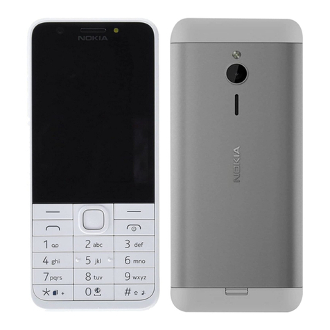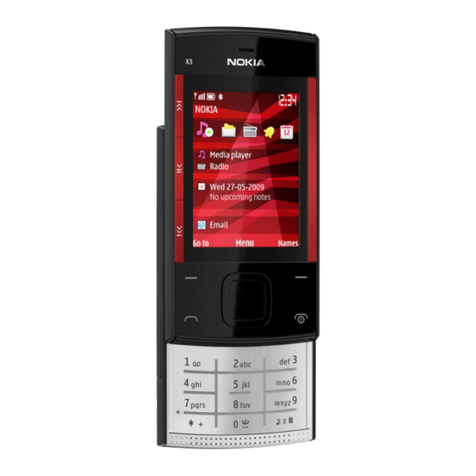
3155/3155i (RM-41), 3152 (RM-61)
Reassembly
Page 2 ©2005 Nokia Corporation Company Confidential ISSUE 1 07/2005
Contents Page
Safety Information ......................................................................................................................................... 3
ESD Protection .............................................................................................................................................3
Reassembly Instructions............................................................................................................................... 4
1. Attach the TX Compression Gasket ...................................................................................................4
2. Insert the D-cover UIM Card Trap ......................................................................................................4
3. Attach the Whip Antenna ....................................................................................................................5
4. Insert the Volume Key ...........................................................................................................................5
5. Insert the IHF Assembly ........................................................................................................................5
6. Insert the DC Jack and Microphone ..................................................................................................6
7. Connect the B-cover and the C-cover ..............................................................................................6
8. Insert the LED Light Guide ...................................................................................................................7
9. Assemble the Engine PWB and the C-cover ...................................................................................7
10. Attach the Flex Cable ..........................................................................................................................7
11. Connect the C-cover and the D-cover ...........................................................................................8
12. Add the Screws .....................................................................................................................................9
13. Add the Keymat ....................................................................................................................................9
14. Attach the Main LCD Display into the B-cover .........................................................................10
15. Attach Earpiece and Acoustic Vent to the B-cover ..................................................................11
16. Attach the UI PWB to the B-cover ................................................................................................11
17. Attach the Main Display Flex Cable to the UI PWB .................................................................12
18. Attach the Secondary LCD Display Flex Cable ...........................................................................12
19. Attach the Display Frame .................................................................................................................12
20. Add the Screws to the A-cover ......................................................................................................13
21. Attach the A-cover ............................................................................................................................13
22. Insert the Battery and Attach the Battery Cover (E-cover) ...................................................14
