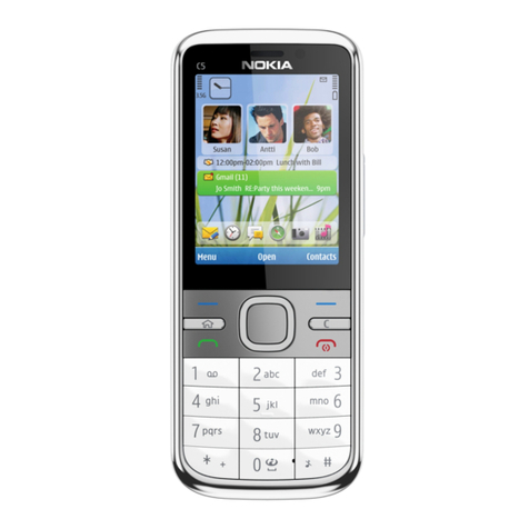
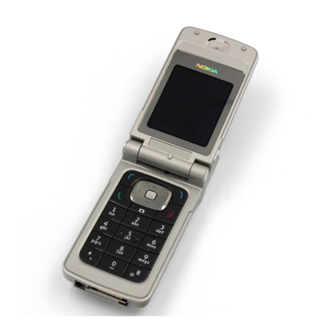
Nokia 3155i Operating instructions

Nokia Customer Care
3155/3155i (RM-41), 3152 (RM-61)
Mobile Terminal
ISSUE 1 07/2005 Company Confidential ©2005 Nokia Corporation
Baseband Description and
Troubleshooting

3155/3155i (RM-41), 3152 (RM-61)
Baseband Description and Troubleshooting
Page 2 ©2005 Nokia Corporation Company Confidential ISSUE 1 07/2005
Contents Page
Introduction ..................................................................................................................................................... 5
Power Up Sequence ....................................................................................................................................6
Flash Programming ........................................................................................................................................ 7
Flashing Tool .................................................................................................................................................7
Flashing Troubleshooting ..........................................................................................................................8
Flashing Phoenix Interface........................................................................................................................ 10
Audio............................................................................................................................................................... 11
How the Audio Works ..............................................................................................................................11
Audio Troubleshooting .............................................................................................................................12
Audio Phoenix Interface ..........................................................................................................................13
FM Radio ........................................................................................................................................................ 14
How the FM Radio Works .......................................................................................................................14
FM Radio Test .............................................................................................................................................14
FM Radio Troubleshooting ......................................................................................................................14
FM Radio Phoenix Interface ...................................................................................................................15
USB (Universal Serial Bus)......................................................................................................................... 17
How the USB Interface Works ...............................................................................................................17
USB Troubleshooting ................................................................................................................................18
Display ............................................................................................................................................................ 20
How the Display Works ............................................................................................................................20
Display Troubleshooting ..........................................................................................................................20
Display Backlight Troubleshooting .......................................................................................................21
Display Phoenix Interface .......................................................................................................................23
Keypad Backlight ......................................................................................................................................... 24
How the Keypad Backlight Works ........................................................................................................24
Keypad Backlight Troubleshooting .......................................................................................................24
Keypad Backlight Display Phoenix Interface .....................................................................................26
GPS................................................................................................................................................................... 27
How GPS Works .........................................................................................................................................27
GPS Troubleshooting ................................................................................................................................27
GPS Phoenix Interface ..............................................................................................................................30
UIM Card........................................................................................................................................................ 31
How the UIM Card Works .......................................................................................................................31
UIM Card Troubleshooting ......................................................................................................................31
UIM Card Phoenix Interface ...................................................................................................................34
System Connector........................................................................................................................................ 35
Accessory Detection.................................................................................................................................... 36
Battery (Lynx) Interface Circuit............................................................................................................... 37
Charging......................................................................................................................................................... 38
Common Problems ...................................................................................................................................... 39
No Communication During Flash ..........................................................................................................39
No Communication During Alignment ................................................................................................39
Failed Self Test/Calibrate .........................................................................................................................39
Mobile Terminal Not Powering Up .......................................................................................................39
Shut Down After 32 Seconds .................................................................................................................39
No Audio ......................................................................................................................................................40
Key Pads Malfunction ..............................................................................................................................40

Nokia Customer Care Baseband Description and Troubleshooting
3155/3155i (RM-41), 3152 (RM-61)
ISSUE 1 07/2005 ©2005 Nokia Corporation Company Confidential Page 3
No LCD Display ...........................................................................................................................................40

Phoenix Tools................................................................................................................................................ 41
Reference ....................................................................................................................................................... 47
Signal references .......................................................................................................................................47
Main PWB Overview .................................................................................................................................48
Test point map - bottom ..................................................................................................................... 48
Test point map - top............................................................................................................................. 49

3155/3155i (RM-41), 3152 (RM-61)
Baseband Description and Troubleshooting
Page 4 ©2005 Nokia Corporation Company Confidential ISSUE 1 07/2005
This page intentionally left blank.

Nokia Customer Care Baseband Description and Troubleshooting
3155/3155i (RM-41), 3152 (RM-61)
ISSUE 1 07/2005 ©2005 Nokia Corporation Company Confidential Page 5
Introduction
The 3155/3155i/3152 baseband module is a tri-mode, Code Division Multiple Access
(CDMA), dual-band engine and is based on the DCT4.5 standard. The baseband engine
includes two major Application Specific Integrated Circuits (ASICs):
• D2200 — Universal Energy Management Enhanced Integrated Circuit (UEME IC),
which includes the audio circuits, charge control, and voltage regulators
• D2800 — Main phone processor, which includes system logic for CDMA, two
Digital Signal Processors (DSPs), the Main Control Unit (MCU), and the memory
The BL-6C Li-ion battery is used as the main power source and has a nominal capacity of
1070 mAh.
Even though the Bluetooth, Camera, Camera flash, External Display and MMC
components are on the ASICs, they are not used in the 3155/3155i/3152 baseband
module.

3155/3155i (RM-41), 3152 (RM-61)
Baseband Description and Troubleshooting
Page 6 ©2005 Nokia Corporation Company Confidential ISSUE 1 07/2005
Power Up Sequence
When the mobile terminal is dead or jammed always check the Power Up Sequence of
the baseband area. Verify all regulator and reset signals are correct to ensure proper
power up of UEMEK and D2800 (see Figure 1).
Figure 1: Power-on sequence and timing
Reference signal
PwrOnX
Charger Detection
RTC
UEMRSTX
VCORE
VFlash1
VIO
VANA
VR3
19.2MHz Clk
PURX
t1 t2 t4t3
Sleep Clock
t1 = 20ms
t2 = 200ms
t3 = 500us
t4 = 20ms
Reset mode is entered and the watchdog
starts. VCORE enabled, providing power to
D2800.
End of settling time (only if Vbat > Vcoff+_);
VFLASH1 regulator enabled
VR3, VANA, VIO enabled; PURX held
LOW
D2800 processor, MCU, and DSP are
reset; VCTCXO regulator forced on

Nokia Customer Care Baseband Description and Troubleshooting
3155/3155i (RM-41), 3152 (RM-61)
ISSUE 1 07/2005 ©2005 Nokia Corporation Company Confidential Page 7
Figure 2: Measured power-on sequence and timing Flash Programming
Flash Programming
Flashing Tool
Flash programming is done through the VPP, FBUSTX, FBUSRX, MBUS, and BSI signals
BSI = Used to indicate to MCU that the prommer is connected and mobile terminal is in
flashing mode
MBUS = Used as clock signal for synchronizing the serial communication between the
prommer and MCU
FBUSRX = Data to UPP
FBUSTX = Data to prommer
VPP = 0v/ 1.8v/ 12v (read only/normal op. or slow programming/fast programming)

3155/3155i (RM-41), 3152 (RM-61)
Baseband Description and Troubleshooting
Page 8 ©2005 Nokia Corporation Company Confidential ISSUE 1 07/2005
Figure 3 shows the DA-47 flashing tool and Module Jig MJ-57.
Figure 3: DA-54 Flashing Tool and MJ-57 Module Jig
Flashing Troubleshooting
When troubleshooting flashing problems, first make sure the signals from the FPS-8 to
the D2800 processor are functioning properly before replacing any component. Once
signals between production test points and the D2200 and the D2800 processor have
been checked, verify that the interface between D2800 processor and flash is correct.
While all the signals between D2800 processor and flash are not visible, the available
signals will help identify the components that may need to be replaced.
Figure 4: Flashing diagram
When troubleshooting the flashing to diagnose and determine faulty components, check
the signals in the following sequence:
• Make sure the signals from the tester are making contact with the production
flash pads.
• Use Phoenix External to either program or erase a mobile terminal that is not
working. This allows you to monitor the signals form the FPS-8 to the D2800
processor.
FBUS TxO
MBUS
FBUS RxO
Production
Test Points
UEMEK D2800 Flash
Memory
MBUS Tx
MBUS Rx
FBUS Tx
FBUS Rx
FLSCSX
EXTRDX
EXTWRD
FLSCLK
D2200 D2800 D3001
Signal voltage
levels are 2.78V Signal voltage
levels are 1.8V Signal voltage
levels are 1.8V
FBUS TxO
MBUS
FBUS RxO
Production
Test Points
UEMEK D2800 Flash
Memory
MBUS Tx
MBUS Rx
FBUS Tx
FBUS Rx
FLSCSX
EXTRDX
EXTWRD
FLSCLK
D2200 D2800 D3001
Signal voltage
levels are 2.78V Signal voltage
levels are 1.8V Signal voltage
levels are 1.8V

Nokia Customer Care Baseband Description and Troubleshooting
3155/3155i (RM-41), 3152 (RM-61)
ISSUE 1 07/2005 ©2005 Nokia Corporation Company Confidential Page 9
• When flashing or erasing the mobile terminal, monitor the MBUSRX and FBUSRX
signals from the UEMEK to the D2800 processor for a signal at these points. If
either signal does not appear, check the signal at the production test points. If
the signal is ok, check the UEMEK. Re-flow or replace the UEMEK.
• Next make sure that the D2800 processor sends information back to the FPS-8
through the FBUSTX signal. If there is no activity at this point re-flow or replace
the processor.
• If all points are ok, make sure the FBUSTX signal goes through the UEMEK by
measuring the signal at the FBUSTXO at production test points. If there is no
signal present, reflow or replace the UEMEK.
• If all signals form the production test points to the UEMEK to the D2800
processor are functioning, it is safe to assume that the UEMEK and D2800
processor are ok.
Continue troubleshooting the D2800 processor as it interfaces with the flash. Verify the
available signal interface between the processor and flash as follows:
• Erase or program the mobile terminal to monitor the D2800 processor and flash
interface as verified earlier using Phoenix External.
• When programming or erasing the mobile terminal, monitor the FLSCSX, FLSCLK,
EXTRDX, and EXTWRX flash signals. If any of these signals has no activity, re-flow
or replace the D2800 processor.
• If all signals are ok, re-flow or replace the flash.
If additional troubleshooting is still required to determine why the mobile terminal
cannot be flashed, verify all the baseband voltages. In particular, check the VIO since it is
one of the regulators that powers the flash chip.

3155/3155i (RM-41), 3152 (RM-61)
Baseband Description and Troubleshooting
Page 10 ©2005 Nokia Corporation Company Confidential ISSUE 1 07/2005
Flashing Phoenix Interface
Run EZ Flash in Phoenix to flash the mobile terminal.
Figure 5: EZ Flash in Phoenix
.
Figure 6: EZ Flash in Phoenix

Nokia Customer Care Baseband Description and Troubleshooting
3155/3155i (RM-41), 3152 (RM-61)
ISSUE 1 07/2005 ©2005 Nokia Corporation Company Confidential Page 11
Audio
How the Audio Works
The baseband supports three microphone inputs and two earpiece outputs. The
microphone inputs are MIC1, MIC2, and MIC3:
• MIC1 input is used for the moblie terminal's internal microphone
• MIC2 input is used for headsets (Pop-Port™)
• MIC3 input is used for the Universal Headset
Every microphone input can have either a differential or single-ended AC connection to
the UEMEK circuit. In the Nokia 3155/3155i/3152, the internal microphone (MIC1) and
external microphone (MIC2) for Pop-Port™ accessory detection are both differential.
However, the Universal Headset interface is single-ended. The microphone signals from
different sources are connected to separate inputs at the UEMEK. Inputs for the
microphone signals are differential types. Also, MICB1 is used for MIC1 and MICB2 is
used for MIC2 and MIC3 (Universal Headset).
Figure 7: Audio components
UHJ MIC3
IHF
Charging jack MIC
Earpiece
Volume keys

3155/3155i (RM-41), 3152 (RM-61)
Baseband Description and Troubleshooting
Page 12 ©2005 Nokia Corporation Company Confidential ISSUE 1 07/2005
Audio Troubleshooting
When troubleshooting the audio, make these common checks (see Figure 8):
• Perform visual inspection of all the ASIPs and the UEMEK.
• Inject 1KHz signal into MiC1 and trace it to the earpiece. Only when using IHF
signal will be amplified by a factor of 8.
Figure 8: UEMEK Side of Audio Diagram
• Make sure the audio amplifier and solder are ok.
• Make sure the IHF speaker contacts are ok.
• Make sure output is amplified by 8x. If not, check that the gain resistors network
is correct.
Figure 9: IHF Troubleshooting
Audio ASIPs
FM Radio Lines
DC Block Caps
Audio ASIPs
UHJ
MIC3
MIC2
Pop-Port™
Earpiece

Nokia Customer Care Baseband Description and Troubleshooting
3155/3155i (RM-41), 3152 (RM-61)
ISSUE 1 07/2005 ©2005 Nokia Corporation Company Confidential Page 13
Audio Phoenix Interface
Run Audio Test in Phoenix to check the audio functionality.
Figure 10: Audio Test in Phoenix
MiC1 - Use the first option to route the audio from
the internal microphone to the headset speaker.
MiC2 - Use the second option to route the audio
signal from the headset microphone to internal ear-
piece.
MiC3 - Use the first and second options to test MIC3.
Open channel and insert the universal headset. The
UEM automatically re-routes the audio signal to the
UHJ.
Earpiece - Use the second option to hear audio from
internal earpiece.
IHF - Use the fifth option to route audio signal to IHF
speaker out.

3155/3155i (RM-41), 3152 (RM-61)
Baseband Description and Troubleshooting
Page 14 ©2005 Nokia Corporation Company Confidential ISSUE 1 07/2005
FM Radio
How the FM Radio Works
The D2800 turns on the FM radio and sets the frequency using the CBUS serial interface
as the communication channel. A high frequency FM radio signal comes in through
RFIN1 Pin to the FM radio chip and gets demodulated into a low frequency signal and is
sent to the UEMEK for amplification. The amplified signal then gets routed back either to
the universal headset or to the system connector for the stereo headset.
Figure 11: FM Radio (N356), Audio (N150), antenna, and digital interface connections
FM Radio Test
To hear the FM radio, you first connect headset to Pop-Port™ or UHJ ports because the
headset is an FM radio antenna. Connect the headset to UHJ port to control the FM radio
using Phoenix. If you connect a headset (such as HDS-3) to a Pop-Port™ connector, then
you cannot control the mobile terminal because you have already occupied the
connection port (Pop-Port™). In this case you have to have jumper wires on the
production test points (Fbus Tx/RX,GND).
FM Radio Troubleshooting
When troubleshooting the FM radio, make these common checks (see Figure 12):
• Check Power Supply VIO and VANA
• Check SleepCLK
• Check FMANT
• Check for activity on CBUS
• Check output of FM radio on VAFR and VAFL
FM Radio TIKUEDGE
HSEARN
HSEARP
HSEARRN
HSEARRP
68nH
40pF
100P
UEMEK
audio
Amplifier
Antenna signal
Sleep CLK
CBUS_DA
CBUS_CLK
CBUS_EN
Xtal1
Data
W/R
Clock
Rfin1
Audio R
Audio L
FMClk
FMCtrlDa
FMCtrlClk
FMWrEn
POP PORT™
System Connector FM Radio TIKUEDGE
HSEARN
HSEARP
HSEARRN
HSEARRP
68nH
40pF
100P
UEMEK
audio
Amplifier
Antenna signal
Sleep CLK
CBUS_DA
CBUS_CLK
CBUS_EN
Xtal1
Data
W/R
Clock
Rfin1
Audio R
Audio L
FMClk
FMCtrlDa
FMCtrlClk
FMWrEn
POP PORT™
System Connector

Nokia Customer Care Baseband Description and Troubleshooting
3155/3155i (RM-41), 3152 (RM-61)
ISSUE 1 07/2005 ©2005 Nokia Corporation Company Confidential Page 15
• If the audio signal not correct (with 800mv DC-offset), then check FM radio chip
for shorts, voids, and misalignments
• If the audio signal is correct (with 800mv DC-offset), then check the UEMEK for
shorts, voids, and misalignments
• If the UEMEK and FM Radio Chip is correct, check the system connector
Figure 12: FM Radio Chip and Antenna
FM Radio Phoenix Interface
Checks for the FM radio that can be perform with Phoenix include:
• Verify the FM radio is working by connecting headset to UHJ
• Turn on the FM radio
• Set frequency and volume
FM Radio Chip (always
the check solder)
FMANT
VAFL
VAFR
VANA (2.8V)
GND
FMANT
XEAR_RN
XEAR_RP
VIO (1.8)
Sleep CLk
INTX

3155/3155i (RM-41), 3152 (RM-61)
Baseband Description and Troubleshooting
Page 16 ©2005 Nokia Corporation Company Confidential ISSUE 1 07/2005
Figure 13: Phoenix FM Radio Control panel
Power On check box
Frequency control
Volume control
Mono/Stereo control
Headset/IHF control
Mute, On/Off control

Nokia Customer Care Baseband Description and Troubleshooting
3155/3155i (RM-41), 3152 (RM-61)
ISSUE 1 07/2005 ©2005 Nokia Corporation Company Confidential Page 17
USB (Universal Serial Bus)
How the USB Interface Works
When the mobile terminal is connected to a computer using a DKU-2 data cable, the
computer will provide Vbus (5V) to and pull down D+ a,d D – lines. The mobile terminal
will respond by pulling the D+ line high. The computer acknowledges and starts
transferring data at 12Mbits/sec.
Figure 14: USB interface block diagram

3155/3155i (RM-41), 3152 (RM-61)
Baseband Description and Troubleshooting
Page 18 ©2005 Nokia Corporation Company Confidential ISSUE 1 07/2005
USB Troubleshooting
First connect mobile terminal to the computer using a DKU-2 data cable. Check under
device manager if the computer recognizes the mobile terminal as a USB device. If the
mobile terminal is recognized, there is no hardware fault and you can stop
troubleshooting.
Figure 15: PC Device Manager
When troubleshooting the USB, make these common checks (see Figure 26 and
Figure 27):
• Perform a visual inspection on Pop-Port™ connector, ESD Protection, NUT Chip,
and caps and Inductors
• Check Vout, Vflash1, and ACI Line. If not correct, check UEMEK under X-ray or
change the part.
• Check for activity on the USB D+ and USB D – lines. If there is no activity, check
D2800 under X-ray or change the part.
Figure 16: USB Chip and Diagram
USB Vbus (5V)
Vout
USD ESD Protection
ACI
USB D+ (3.3V)
USB D- (3.3V)
USB D+
USB D-
VFlash1 (2.8V)

Nokia Customer Care Baseband Description and Troubleshooting
3155/3155i (RM-41), 3152 (RM-61)
ISSUE 1 07/2005 ©2005 Nokia Corporation Company Confidential Page 19
Figure 17: USB Vout

3155/3155i (RM-41), 3152 (RM-61)
Baseband Description and Troubleshooting
Page 20 ©2005 Nokia Corporation Company Confidential ISSUE 1 07/2005
Display
How the Display Works
Nokia 3155/3155i/3152 has a large main display (160 x 130 color depth), controlled by
the D2800 engine through a parallel interface. The secondary, black and white display
(96 x 68) is controlled by the D2800 engine through a serial interface. The UEMEK
powers using VIO and VFlash1.
Figure 18: Nokia 3155/3155i/3152 UI Display
Display Troubleshooting
When troubleshooting the display, make these common checks (see Figure 19):
• Check that the display is connected properly and is making good contact with
LCD connector. If no display, replace the LCD.
• Check the power supply VIO and VFlash1. If not correct, check the UEMEK.
• Check the activity on the LCD test points. If no activity, check or replace D2800
• Check the parallel interface (DIF) for the main display
• Check that the DIF CLk is 4.8MHz
• Check the serial interface (LCD) for the secondary display
• Check that the LCD CLk is 2.4MHz
Main display:
262K color (128x160)
Secondary display:
Black & White (96 x 65)
4-way navigation
key with center-
select
External keys
Soft keys
UHJ Headset jack/
sliding cover
Volume key
Push-to-Talk key
Other manuals for 3155i
2
This manual suits for next models
2
Table of contents
Other Nokia Handheld manuals