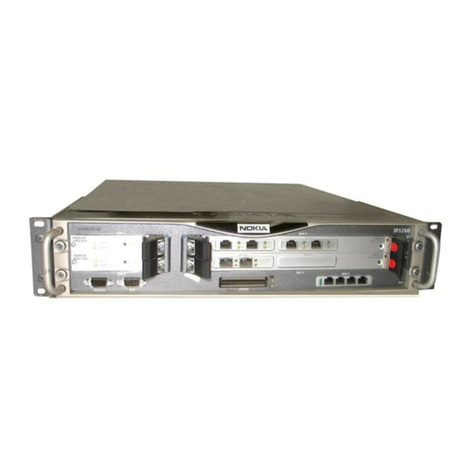
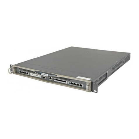
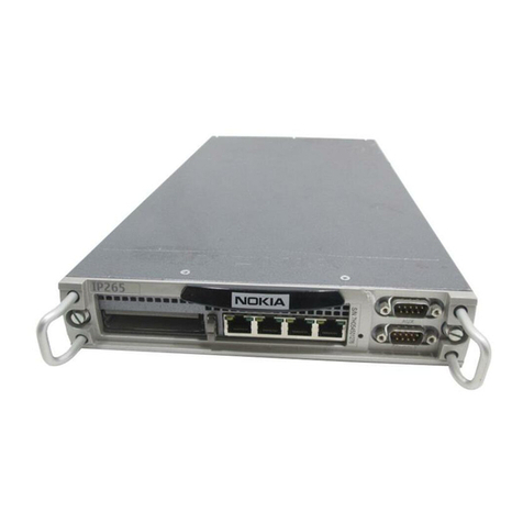
Nokia IP150 User manual

Part No. N450000898 Rev 001
Published April 2009
Check Point IP150 Security
Platform Installation Guide

2 Check Point IP150 Security Platform Installation Guide
© 2003-2009 Check Point Software Technologies Ltd.
All rights reserved. This product and related documentation are protected by copyright and
distributed under licensing restricting their use, copying, distribution, and decompilation. No
part of this product or related documentation may be reproduced in any form or by any means
without prior written authorization of Check Point. While every precaution has been taken in the
preparation of this book, Check Point assumes no responsibility for errors or omissions. This
publication and features described herein are subject to change without notice.
RESTRICTED RIGHTS LEGEND:
Use, duplication, or disclosure by the government is subject to restrictions as set forth in
subparagraph (c)(1)(ii) of the Rights in Technical Data and Computer Software clause at DFARS
252.227-7013 and FAR 52.227-19.
TRADEMARKS:
Please refer to http://www.checkpoint.com/copyright.html for a list of our trademarks.
For third party notices, see http://www.checkpoint.com/3rd_party_copyright.html.
Check Point Contact Information
For additional technical information about Check Point products, and for the latest version of
this document, see the Check Point Support Center at http://support.checkpoint.com/.
Check Point is engaged in a continuous effort to improve its documentation. Please help us by
sending your comments to:

Check Point IP150 Security Platform Installation Guide 3
Contents
Check Point Contact Information. . . . . . . . . . . . . . . . . . . . . . . . . . . . . . . . . . . . . . . 2
About this Guide . . . . . . . . . . . . . . . . . . . . . . . . . . . . . . . . . . . . . . . . . . . . . . . . . . . 9
In This Guide . . . . . . . . . . . . . . . . . . . . . . . . . . . . . . . . . . . . . . . . . . . . . . . . . . . . . . . 9
Conventions This Guide Uses . . . . . . . . . . . . . . . . . . . . . . . . . . . . . . . . . . . . . . . . . . 9
Notices . . . . . . . . . . . . . . . . . . . . . . . . . . . . . . . . . . . . . . . . . . . . . . . . . . . . . . . . . 10
Text Conventions . . . . . . . . . . . . . . . . . . . . . . . . . . . . . . . . . . . . . . . . . . . . . . . . . 10
1 Overview . . . . . . . . . . . . . . . . . . . . . . . . . . . . . . . . . . . . . . . . . . . . . . . . . . . . . . . . 11
About the Check Point IP150 Security Platform. . . . . . . . . . . . . . . . . . . . . . . . . . . . 11
Check Point IP150 Security Platform Appliance Overview . . . . . . . . . . . . . . . . . . . 11
Built-in Ethernet Ports . . . . . . . . . . . . . . . . . . . . . . . . . . . . . . . . . . . . . . . . . . . . . . 12
Console and Serial (AUX) Ports . . . . . . . . . . . . . . . . . . . . . . . . . . . . . . . . . . . . . . 13
System Status LEDs . . . . . . . . . . . . . . . . . . . . . . . . . . . . . . . . . . . . . . . . . . . . . . . 14
Site Requirements . . . . . . . . . . . . . . . . . . . . . . . . . . . . . . . . . . . . . . . . . . . . . . . . . . 15
Product Disposal . . . . . . . . . . . . . . . . . . . . . . . . . . . . . . . . . . . . . . . . . . . . . . . . . . . 15
Safety Warnings and Cautions. . . . . . . . . . . . . . . . . . . . . . . . . . . . . . . . . . . . . . . . . 16
Managing IP150 Security Platform Appliances . . . . . . . . . . . . . . . . . . . . . . . . . . . . 16
2 Installing a Check Point IP150 Security Appliance . . . . . . . . . . . . . . . . . . . . . . 19
Rack Mounting a Check Point IP150 Appliance . . . . . . . . . . . . . . . . . . . . . . . . . . 19
3 Connecting to the Ethernet Ports . . . . . . . . . . . . . . . . . . . . . . . . . . . . . . . . . . . . 21
Built-In Four-Port 10/100/1000 Ethernet Interface . . . . . . . . . . . . . . . . . . . . . . . . . . 21
Ethernet Features . . . . . . . . . . . . . . . . . . . . . . . . . . . . . . . . . . . . . . . . . . . . . . . . . 21
Connecting to Ethernet Ports . . . . . . . . . . . . . . . . . . . . . . . . . . . . . . . . . . . . . . . . 22
4 Performing the Initial Configuration . . . . . . . . . . . . . . . . . . . . . . . . . . . . . . . . . . 25
Using a Console Connection . . . . . . . . . . . . . . . . . . . . . . . . . . . . . . . . . . . . . . . . . . 25
Connecting Power and Turning the Power On. . . . . . . . . . . . . . . . . . . . . . . . . . . . . 26
Performing the Initial Configuration . . . . . . . . . . . . . . . . . . . . . . . . . . . . . . . . . . . . . 27
Connecting Network Interfaces . . . . . . . . . . . . . . . . . . . . . . . . . . . . . . . . . . . . . . . . 29
Using Check Point Network Voyager . . . . . . . . . . . . . . . . . . . . . . . . . . . . . . . . . . . . 29
Viewing Check Point IPSO Documentation by Using

4 Check Point IP150 Security Platform Installation Guide
Check Point Network Voyager . . . . . . . . . . . . . . . . . . . . . . . . . . . . . . . . . . . . . 29
Using the Command-Line Interface . . . . . . . . . . . . . . . . . . . . . . . . . . . . . . . . . . . . 30
Using Check Point Horizon Manager . . . . . . . . . . . . . . . . . . . . . . . . . . . . . . . . . . . 31
Using Check Point SmartCenter and Provider-1. . . . . . . . . . . . . . . . . . . . . . . . . . . 32
5 Installing and Replacing Components . . . . . . . . . . . . . . . . . . . . . . . . . . . . . . . . . 33
Replacing the Compact Flash Memory Card . . . . . . . . . . . . . . . . . . . . . . . . . . . . . 33
Before You Start. . . . . . . . . . . . . . . . . . . . . . . . . . . . . . . . . . . . . . . . . . . . . . . . . . 34
Replacing a Hard-Disk Drive. . . . . . . . . . . . . . . . . . . . . . . . . . . . . . . . . . . . . . . . . . 37
Before You Start. . . . . . . . . . . . . . . . . . . . . . . . . . . . . . . . . . . . . . . . . . . . . . . . . . 39
Replacing or Upgrading Memory . . . . . . . . . . . . . . . . . . . . . . . . . . . . . . . . . . . . . . 42
Before You Start. . . . . . . . . . . . . . . . . . . . . . . . . . . . . . . . . . . . . . . . . . . . . . . . . . 43
Installing or Replacing the Check Point Encryption Accelerator Card . . . . . . . . . . 46
Before You Start. . . . . . . . . . . . . . . . . . . . . . . . . . . . . . . . . . . . . . . . . . . . . . . . . . 47
Configuring and Activating Check Point Encryption Acceleration . . . . . . . . . . . . 49
Replacing the Battery . . . . . . . . . . . . . . . . . . . . . . . . . . . . . . . . . . . . . . . . . . . . . . . 50
6 Troubleshooting . . . . . . . . . . . . . . . . . . . . . . . . . . . . . . . . . . . . . . . . . . . . . . . . . . . 55
General Troubleshooting Information . . . . . . . . . . . . . . . . . . . . . . . . . . . . . . . . . . . 55
A Technical Specifications . . . . . . . . . . . . . . . . . . . . . . . . . . . . . . . . . . . . . . . . . . . . 59
Physical Dimensions . . . . . . . . . . . . . . . . . . . . . . . . . . . . . . . . . . . . . . . . . . . . . . . . 59
Space Requirements. . . . . . . . . . . . . . . . . . . . . . . . . . . . . . . . . . . . . . . . . . . . . . . . 59
Other Specifications . . . . . . . . . . . . . . . . . . . . . . . . . . . . . . . . . . . . . . . . . . . . . . . . 59
Appliance Interfaces . . . . . . . . . . . . . . . . . . . . . . . . . . . . . . . . . . . . . . . . . . . . . . . . 60
B Compliance Information . . . . . . . . . . . . . . . . . . . . . . . . . . . . . . . . . . . . . . . . . . . . 61
Declaration of Conformity . . . . . . . . . . . . . . . . . . . . . . . . . . . . . . . . . . . . . . . . . . . . 61
Compliance Statements . . . . . . . . . . . . . . . . . . . . . . . . . . . . . . . . . . . . . . . . . . . . . 62
FCC Notice (US) . . . . . . . . . . . . . . . . . . . . . . . . . . . . . . . . . . . . . . . . . . . . . . . . . . . 63
Index. . . . . . . . . . . . . . . . . . . . . . . . . . . . . . . . . . . . . . . . . . . . . . . . . . . . . . . . . . . . . 65

Check Point IP150 Security Platform Installation Guide 5
Tables
Table 1 Text Conventions . . . . . . . . . . . . . . . . . . . . . . . . . . . . . . . . . . . . . . . . . . . 10
Table 2 Pin Assignments for DB9 and DB25 Interface Cables . . . . . . . . . . . . . . . 14
Table 3 Appliance Status LEDs . . . . . . . . . . . . . . . . . . . . . . . . . . . . . . . . . . . . . . . 15

6 Check Point IP150 Security Platform Installation Guide

Check Point IP150 Security Platform Installation Guide 7
Figures
Figure 1 Component Locations Front View . . . . . . . . . . . . . . . . . . . . . . . . . . . . . . 12
Figure 2 Component Locations Rear View . . . . . . . . . . . . . . . . . . . . . . . . . . . . . . 12
Figure 3 Built-In Ethernet Interface Front Panel Details . . . . . . . . . . . . . . . . . . . . 12
Figure 4 Pin Assignments for Console Connections . . . . . . . . . . . . . . . . . . . . . . . 13
Figure 5 Appliance Status LEDs . . . . . . . . . . . . . . . . . . . . . . . . . . . . . . . . . . . . . . 14
Figure 6 Installing the Mounting Brackets . . . . . . . . . . . . . . . . . . . . . . . . . . . . . . . 19
Figure 7 Rack-mounted IP150 Appliance . . . . . . . . . . . . . . . . . . . . . . . . . . . . . . . 20
Figure 8 Output Connector for the Ethernet Cable . . . . . . . . . . . . . . . . . . . . . . . . 22
Figure 9 Ethernet Crossover Cable Pin Connections . . . . . . . . . . . . . . . . . . . . . . 23
Figure 10 Power Switch Location . . . . . . . . . . . . . . . . . . . . . . . . . . . . . . . . . . . . . 26
Figure 11 Check Point Network Voyager Reference Access Points . . . . . . . . . . . 30
Figure 12 Hard-Disk Drive Location . . . . . . . . . . . . . . . . . . . . . . . . . . . . . . . . . . . 38
Figure 13 DIMM Socket Locations . . . . . . . . . . . . . . . . . . . . . . . . . . . . . . . . . . . . 42

8 Check Point IP150 Security Platform Installation Guide

Check Point IP150 Security Platform Installation Guide 9
About this Guide
This guide provides information for the installation and use of the Check Point IP150 security
platform. Installation and maintenance should be performed by experienced technicians or
Check Point-approved service providers only.
This preface provides the following information:
In This Guide
Conventions This Guide Uses
In This Guide
This guide is organized into the following chapters and appendixes:
Chapter 1, “Overview” presents a general overview of the Check Point IP150 Security
Platform.
Chapter 2, “Installing a Check Point IP150 Security Appliance” explains how to rack mount
the appliance and how to physically connect it to a network and power.
Chapter 3, “Connecting to the Ethernet Ports” describes how to connect to the supported
Ethernet ports.
Chapter 4, “Performing the Initial Configuration” explains how to make the appliance
available on the network.
Chapter 5, “Installing and Replacing Components”describes how to configure and activate
the built-in encryption acceleration feature.
Chapter 6, “Troubleshooting” discusses problems you might encounter and proposes
solutions to these problems.
Appendix A, “Technical Specifications” gives technical specifications such as interface
characteristics.
Appendix B, “Compliance Information” includes compliance and regulatory information.
Conventions This Guide Uses
The following sections describe the conventions this guide uses, including notices, text
conventions, and command-line conventions.

About this Guide
10 Check Point IP150 Security Platform Installation Guide
Notices
Warning
Warnings advise the user that bodily injury might occur because of a physical hazard.
Caution
Cautions indicate potential equipment damage, equipment malfunction, loss of
performance, loss of data, or interruption of service.
Note
Notes provide information of special interest or recommendations.
Text Conventions
Table 1 describes the text conventions this guide uses.
Table 1 Text Conventions
Convention Description
monospace font
Indicates command syntax, or represents computer or
screen output, for example:
Log error 12453
bold monospace font Indicates text you enter or type, for example:
# configure nat
Key names Keys that you press simultaneously are linked by a
plus sign (+):
Press Ctrl + Alt + Del.
Menu commands Menu commands are separated by a greater than
sign (>):
Choose File > Open.
The words enter and type Enter indicates you type something and then press
the Return or Enter key.
Do not press the Return or Enter key when an instruc-
tion says type.
Italics •Emphasizes a point or denotes new terms at the
place where they are defined in the text.
•Indicates an external book title reference.
•Indicates a variable in a command:
delete interface
if_name

Check Point IP150 Security Platform Installation Guide 11
1Overview
This chapter provides an overview of the Check Point IP150 Security Platform and the
requirements for using the IP150 appliances. The following topics are covered:
About the Check Point IP150 Security Platform on page 11
Check Point IP150 Security Platform Appliance Overview on page 11
Site Requirements on page 15
Safety Warnings and Cautions on page 16
Product Disposal on page 15
Managing IP150 Security Platform Appliances on page 16
About the Check Point IP150 Security Platform
The Check Point IP150 appliance is a multi-purpose, one-rack unit (1 RU), disk-based security
appliance offering powerful yet cost effective UTM, traditional firewall, and next-generation
UTM applications (including firewall, VPN, intrusion protection, antivirus, and web filtering).
With four ports of 10/100/1000 Base-T (RJ-45) Ethernet on-board, it delivers up to 500 Mbps
large-packet stateful firewall throughput and 75 Mbps of IPSec VPN performance. The IP150
offers high-performance, cost-effective security that helps businesses stop internal and external
attacks, prevent unauthorized access, and achieve regulatory compliance.
For technical specifications, see “Technical Specifications” on page 59.
Check Point IP150 Security Platform Appliance Overview
The following figures show component locations for Check Point IP150 appliances.

1
12 Check Point IP150 Security Platform Installation Guide
Figure 1 Component Locations Front View
Figure 2 Component Locations Rear View
Built-in Ethernet Ports
Figure 3 shows the layout of the built-in Ethernet ports and LEDs.
Figure 3 Built-In Ethernet Interface Front Panel Details
00662
IP150
AUX CONSOLE
POWER
STATUS
FAU LT
1234
Built-in Ethernet ports
(10/100/1000 Mbps)
Status LEDs
Auxiliary (AUX) port
Console port
00663
Power plug
Power switch
00120
Activity LED (yellow)
Link LED (green)
RJ-45 connectors

Check Point IP150 Security Platform Appliance Overview
Check Point IP150 Security Platform Installation Guide 13
Console and Serial (AUX) Ports
Use the built-in console port to supply the information that makes the appliance available on the
network. Use the built-in USB (AUX) port for RS232-compliant equipment you are using with
your appliance; for example, as a modem connection for managing the appliance. Figure 4
provides pin assignment information for console and serial connections.
Caution
Check Point recommends that you use the console cable that was delivered with your
appliance for your console connection. Otherwise, ensure that the pin assignments for
your cable match those provided in this section.
Figure 4 Pin Assignments for Console Connections
00460
69
5
1Pin# Assignment
Input or
output
1 not used
2RXD Input
3 TXD Output
4 DTR Output
5GND
6DSR Input
7 RTS Output
8CTS Input
9 not used

1
14 Check Point IP150 Security Platform Installation Guide
Table 2 shows how to match pins at the console connector with output pins on DB9 or DB25
cables you are using with terminal devices or other appropriate equipment.
System Status LEDs
You can monitor the basic operation of Check Point IP150 appliances by checking their status
LEDs. The system status LEDs are located on the front panel of the appliance, as Figure 5
shows.
Figure 5 Appliance Status LEDs
Table 2 Pin Assignments for DB9 and DB25 Interface Cables
Console or serial
pin and assignment
DB9 cable output pin and
assignment
DB25 cable output pin and
assignment
Shield (FG) Shield (FG) 1 (FG)
2 (RXD) 3 (TXD) 2 (TXD)
3 (TXD) 2 (RXD) 3 (RXD)
4 (DTR) 6 (DSR) 6 (DSR)
5 (SG) 5 (SG) 7 (SG)
6 (DSR) 4 (DTR) 20 (DTR)
7 (RTS) 8 (CTS) 5 (CTS)
8 (CTS) 7 (RTS) 4 (RTS)
00662
IP150
AUX CONSOLE
POWER
STATUS
FAU LT
1234
Power
Status
Fault

Site Requirements
Check Point IP150 Security Platform Installation Guide 15
Table 3 describes the Status LEDs and each status indicator or condition that might display.
For information about the built-in Ethernet interface LEDs, see “Built-in Ethernet Ports” on
page 12.
Site Requirements
Before you install a Check Point IP150 appliance, ensure that your computer room or wiring
closet conforms to the environmental specifications listed in Appendix A, “Technical
Specifications.”
Product Disposal
Table 3 Appliance Status LEDs
Status LED Status Indicator (Color) Description
Power None (off)
Blue
Power off
Power on
Status None (off)
Yellow (steady)
Yellow (blinking)
Normal
Initial boot flash activity
or
Internal voltage problem
Temperature fault
Fault None (off)
Red (steady)
Normal
Initial boot flash activity
or
One or more fans are defective.
This symbol on the product or on its packaging indicates that this product must not
be disposed of with your other household waste. Instead, it is your responsibility to
dispose of your waste equipment by handing it over to a designated collection point
for the recycling of waste electrical and electronic equipment. The separate
collection and recycling of your waste equipment at the time of disposal will help to
conserve natural resources and ensure that it is recycled in a manner that protects
human health and the environment. For more information about where you can drop
off your waste equipment for recycling, please contact your local city office or your
household waste disposal service.

1
16 Check Point IP150 Security Platform Installation Guide
Safety Warnings and Cautions
Warning
To reduce the risk of fire, electric shock, and injury when you use telephone equipment,
follow basic safety precautions. Do not use the product near water.
Caution
Do not place objects over the ventilation holes on the IP150 appliance. The
components might overheat and become damaged.
Caution
For IP150 appliances intended for shipment outside of the United States, the power
cord might not be included. If a power cord is not provided, use a power cord rated at
6A, 250V, maximum 15 feet long, made of HAR cordage and IEC fittings approved by
the country of end use.
Managing IP150 Security Platform Appliances
You can manage Check Point IP150 appliances by using one of the following interfaces:
Check Point Network Voyager—an SSL-secured, Web-based element management
interface to Check Point IP security platforms. Network Voyager is preinstalled on the IP150
appliance and enabled through the Check Point IPSO operating system. With Network
Voyager, you can manage, monitor, and configure the IP150 appliance from any authorized
location within the network by using a standard Web browser.
For information about how to access Network Voyager and the related reference materials,
see “Using Check Point Network Voyager” on page 29.
The Check Point IPSO command-line interface (CLI)—an SSHv2-secured interface that
enables you to configure Check Point IP security platforms from the command line.
Everything that you can accomplish with Check Point Network Voyager—to manage and
configure the IP150 appliance—you can also do with the CLI.
For information about how to access the CLI, see the CLI Reference Guide for the version of
Check Point IPSO you are using.
Check Point Horizon Manager for IP appliances—a secure GUI-based software image
management application. With Check Point Horizon Manager, you can securely install and
upgrade the Check Point IPSO operating system and applications such as Check Point
VPN-1. Check Point Horizon Manager can perform installations and upgrades on up to
2,500 Check Point IP security platforms, offering administrators the most rapid and
dependable method to perform Check Point application upgrades.

1
18 Check Point IP150 Security Platform Installation Guide

Check Point IP150 Security Platform Installation Guide 19
2Installing a Check Point IP150 Security
Appliance
You can rack mount Check Point IP150 Security appliances in a one-unit space (1U) in a
standard-configuration appliance rack.
Rack Mounting a Check Point IP150 Appliance
Before you mount the appliance on the rack, install the two side brackets with three screws on
each side as shown in Figure 6. The brackets and screws are included with the materials you
receive with the appliance.
Figure 6 Installing the Mounting Brackets
IP150
AUXCONS
OLE
POWER
STA
TUS
FAUL
T
1234
00666
Serrated notches face up
Table of contents
Other Nokia Security System manuals

Nokia
Nokia IP560 - Hard Disk Drive Based User manual

Nokia
Nokia IP40 - Satellite Unlimited - Security... User manual

Nokia
Nokia IP561 User manual

Nokia
Nokia IP1200 Series User manual

Nokia
Nokia IP1220 - Security Appliance User manual

Nokia
Nokia IP60 - Security Appliance User manual

Nokia
Nokia IP200 Series User manual

Nokia
Nokia EM5400 User manual

Nokia
Nokia 6 User manual

Nokia
Nokia IPSO IP350 User manual