MEDAES Medipoint 125 Manual


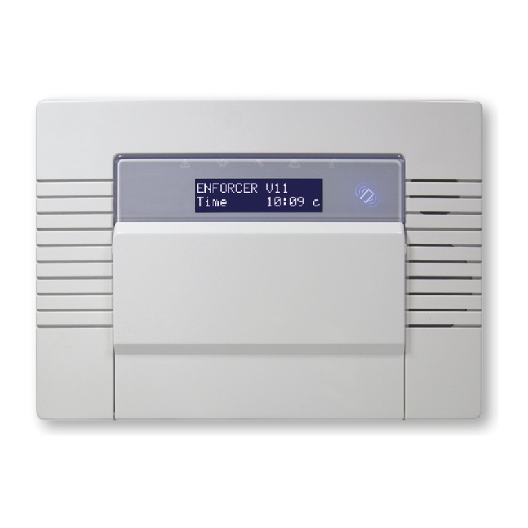
Operating and
Maintenance
Instructions
MEDIPOINT 125
MEDICAL GAS CENTRAL
ALARM
CONTENTS
SECTION
0. SAFETY, STORAGE AND HANDLING DATA
0.1 Indentification of symbols
0.2 Environmental conditions
0.3 Environmental protection
0.4 Electromagnetic interference
0.5 Cleaning of panels
0.6 Electrical details
1. DESCRIPTION AND OPERATION
1.1 Introduction
1.2 Standards
1.3 Alarm panels
1.4 Visual displays
1.5 TEST and MUTE switches
1.6 Audible warnings
1.7 Printed circuit boards
1.7.1 Light display printed circuit board
1.7.2 Power supply printed circuit board
1.7.3 Standby battery
1.8 Alarm contact line fault
1.9 Remote audible warning devices
1.10 Medipoint 125 Relay interface panel
1.11 Operation of the alarm system
1.12 Programming of the alarm system
2. COMMISSIONING
2.1 Introduction
2.2 Functional tests
2.3 Alarm panel. Check internal connections
2.4 Electrical power supply. Switch ON.
2.5 Alarm Panel. Test
2.6 Gas service. Check alarm conditions
2.7 Audible warning. Check
2.8 Remote audible. Check
2.9 Relay interface panel. Check
2.10 SYSTEM ALARM indication. Check
2.11 Central alarm panel(s). Check MUTE operation.
2.12 Alarm system. Set.
3. OPERATING INSTRUCTIONS
3.1 General Operation
3.2 SYSTEM ALARM light
3.3 TEST switch operation
3.4 MUTE switch operation
4. MAINTENANCE
4.1 Introduction
4.2 Tools and equipment
4.3 Customer recommended maintenance
4.4 Weekly inspection
4.5 Quarterly inspection
4.6 Annual inspection
4.7 LED indicator replacement
4.8 Replacing the light display printed circuit board
4.9 Replacing a power supply printed circuit board
4.10 Replacing a back up battery
5. FAULT DIAGNOSIS
5.1 Introduction
6. RECOMMENDED SPARES
6.1 Spares scheduling

Table
1. Medipoint 125 – dimensions
2. Medipoint 125 alarm logic – input panel to repeater panel
3. Medipoint 125 alarm logic – repeater to repeater panel
4. Medipoint 125 programming
5. Medipoint 125 Relay interface programming
6. Test or mute switch fails to operate
7. Single LED indicator fails to illuminate
8. Alarm Panel loses all displays except system alarm
9. System alarm/fault indication with a serviceable gas
10. Remote alarm/recording system not operating correctly
11. Gas service indicates normal with a Gas Service failure condition
12. System alarm and audible fail to operate on power failure
13. A gas service display flashing (including normal) with
System Alarm
14. Minimum recommended spares scheduling per annum
Figure
1. Light display – switch positions
2. Relay panel – switch positions

0. SAFETY, STORAGE
AND HANDLING
DATA
This section gives safety, storage, and handling information for Hill-Rom MEDÆS Ltd.
Medipoint 125 medical gas central alarm. Circuit diagrams, component parts lists
and descriptions are available on request.
0.1 Identification of symbols
The following standard symbols apply to this product. The meanings of these
symbols are as specified below: -
- Read instructions
- Temperature range
- Date of manufacture (Year/Month)
- 3 phase alternating current with neutral conductor
- Protected earth connection
- Type B applied part (as per BSEN60601-1: 1990)
- Dangerous voltage
0.2 Environmental Transport and Storage Conditions
Minimum ambient temperature - 0 degrees Celsius
Maximum ambient temperature - 40 degrees Celsius
Minimum relative humidity (non-condensing) - 10%
Maximum relative humidity (non-condensing) - 95%
Environmental Operating Conditions
Minimum ambient temperature - 0 degrees Celsius
Maximum ambient temperature - 40 degrees Celsius
Minimum relative humidity (non-condensing) - 10%
Maximum relative humidity (non-condensing) - 95%
Atmospheric pressure range - 700-1100 hPa
0.3 Environmental Protection
Discard the unit and/or components in any standard refuse facility. The unit
does not contain any hazardous substances.
0.4 Electromagnetic Interference
The panel has been tested to BSEN60601-1-2: 1993 Medical electrical
equipment - electromagnetic compatibility - requirements and tests. Ensure
all input and data cables are physically separated from other mains and
data cables.

0.5 Cleaning
The panel should be wiped over frequently with a damp cloth to remove any
dust or foreign substances.
0.6 Electrical Details
WARNING...
IT IS NECESSARY TO CHECK THE INTEGRITY OF THE POWER SOURCE FOR SAFETY
AT REGULAR INTERVALS. THESE CHECKS SHOULD BE CARRIED OUT ANNUALLY
AND REPLACEMENT POWER SUPPLIES USED AS NECESSARY.
Power source
Mains operated using 110 or 230V, 50/60Hz, alternating current. The label
adjacent to the mains connection shows whether the voltage is 110 or 230V.
Current requirements
3.0 amps
Type of protection against electric shock
Class 1 (Mains supplied equipment using a protected earth)
Mode of operation
Continuous (equipment may be left switched on indefinitely)
Degree of protection against ingress of liquids
IPX0 (Not protected)
Degree of mobility
Permanently installed (This unit is electrically connected by permanent
means)
Degree of protection
Type B (no Applied Part or with an Applied Part not designed to meet F type
(floating) requirements)
Degree of protection against flammable anaesthetic mixtures
Not protected (not suitable for use with flammable gases)
Rechargeable battery
The rechargeable battery (ref. no. 1828825) should be replaced every 5
years.
0. SAFETY, STORAGE
AND HANDLING
DATA
continued

1. DESCRIPTION AND
OPERATION
1.1 Introduction
The Hill-Rom MEDÆS Medipoint 125 medical gas central alarm system is
designed to provide full monitoring of a complete medical gas installation
throughout a hospital. Medipoint 125 medical gas central alarm systems
consist of a central panel, which normally displays all monitored gas services
with repeater panels in locations as specified by the customer. Inputs from
the respective medical gas supply systems enter the alarm system at the
nearest alarm panel, thereby reducing the installation costs. Information is
transmitted for display throughout the system by means of an advanced
data transmission circuit. Medipoint 125 medical gas central alarm systems
provide a totally flexible alarm system which may be adapted to fully satisfy
the requirements of any application. Programming is performed by switches
within the panel and a system is normally programmed during build, however
panels are easily programmed and systems can easily be modified or
extended on site.
An individual Medipoint 125 alarm panel displays up to 5 gas services in a
‘normal’ and ‘4 stage’ alarm conditions, or may be used to display a
maximum of 20 ‘traditional’ individual point alarms. Mounting multiple
Medipoint 125 alarm panels in adjacent positions enables the Medipoint 125
central alarm system to monitor and display the required number of gas
services. Facilities are incorporated to provide any combination of gas
service or point alarm displays.
One Medipoint 125 alarm panel is designated the master panel for control
purposes. Any number of panels may be programmed as a ‘central panel’
and cause all flashing displays on the system to change to steady when the
MUTE switch on the central panel is operated. Each Medipoint 125 alarm
panel connects directly with the mains electrical power supply and alarm
panels are available for use with supplies of either 100V to 127V a.c. or 200V
to 240V a.c. 50/60 Hz. Electrical power supplies should be from an essential
circuit and fused at 3 Amps.
Each Medipoint 125 alarm panel incorporates flashing alarm displays, a
POWER ON indication, a SYSTEM ALARM indication, MUTE and TEST switches
and an audible warning programmed to operate depending upon the
alarm condition displayed. Alarm panels are interconnected by data
transmission cable. Relay interface units input conditions into existing alarm
systems or building management systems are available.
1.2 Standards
The Hill-Rom MEDÆS Medipoint 125 medical gas central alarm system is
specifically designed and manufactured to fully satisfy the National Health
Service – Model Engineering Specification C11, and is therefore ideal for
HTM2022 applications. Hill-Rom MEDÆS Medipoint 125 medical gas alarms
are suitable for both United Kingdom and International markets, and are fully
tested prior to dispatch and packaged to provide maximum protection
during transit. Alarm panel printed circuit boards are designed to operate in
an ambient temperature of between 0c and +50c. Component assemblies
must be stored in their packaging in dry conditions and storage temperatures
must be between 0oC and +50oC. Alarm panel enclosures provide
protection to IP32 (BS5490) and are electrically bonded to earth to provide
safe installation.
1.3 Alarm Panels
Each alarm panel consists of a first and second fix assembly, and are
suitable for use with either surface or concealed installations. A bezel plate is
provided for use with concealed installations and is fitted to the first fix
assembly to give a neat appearance by covering the plaster joint. The front
cover of the enclosure is hinged and retained by a special fastener which
prevents unauthorised access. The assembly contains two printed circuit
boards and provides a gas service display through windows in the front
cover. The front cover has a flush dark finish polyester fascia to highlight the
displays. Five columns of display windows indicate ‘Normal’ and ‘4 alarm
conditions’, for each gas service monitored. Displays are illuminated by
coloured LED block indicators and have captions to indicate the gas service,
‘Normal’ and ‘Alarm’ conditions. The alarm panel also incorporates a green
LED to indicate that the electrical power supply is ON, and a red LED to
indicate an alarm system fault (SYSTEM ALARM). A MUTE switch is provided to
mute the audible warning and a TEST switch is provided to test the internal
circuits, LED’s and audible warning within the panel. Overall dimensions are
detailed at Table 1.

TABLE 1 : MEDIPOINT 125 – DIMENSIONS
Alarm Panel Bezel
Height (mm) 196.0 246.0
Length (mm) 260.0 310.0
Depth (mm) 61.2 18 swg
Chase depth (mm) 45.0 -
Gas service legends are printed on acetate strips, which slide into the alarm
panel front cover through the uppermost internal slots. The correct
combination of gas service legends must be fitted to satisfy the requirements
of a particular location with blank strips fitted to display columns not used.
Normal C11/HTM2022 legends are available as standard any special
legends, point alarm legends etc. must be ordered as specials.
1.4 Visual displays
Coloured LED’s fitted to the light display pcb provide the following visual
displays:-
1.4.1 Power On indication:- is displayed by a green LED which is
extinguished in the event of a power failure.
1.4.2 System alarm indication:- is displayed by a red LED which is normally
extinguished. This red LED illuminates in a flashing mode to draw
attention to any of the following failures:-
Alarm contact line fault (Sec .1.8).
Electrical power supply failure (powered by a standby battery).
Internal alarm failure.
Data transmission failure.
1.4.3 Normal gas service indication:- is displayed by a steady illuminated
green LED which is extinguished in the event of an alarm condition
1.4.4 Alarm conditions:- are displayed by flashing LED’s (yellow or red) to
draw attention to the specific alarm condition.
All Flashing displays are programmed at sixty flashes per minute, i.e. 0.5
seconds on, 0.5 seconds off in accordance with C11 and HTM2022.
1.4.5 Display positions
To provide an aesthetic display and maintain consistency in
accordance with recognised and established Medical gas service
sequencing, it is recommended that displays are positioned in the
following sequence on each alarm panel commencing with the left
hand column:-
Medical Oxygen (cryogenic and manifolds)
Nitrous oxide (manifolds)
Oxygen/Nitrous oxide (manifolds)
Medical Air 400 kPa (plant and manifolds)
Medical Air 700 kPa (plant and manifolds)
AGS (simplex or duplex)
Point alarms (as required)
When an alarm panel is required to display less than its maximum of 5 gas
services, it is recommended that displays are positioned in accordance with
the following:-
1 Gas Service Display column 3
2 Gas Service Display column 2 and 3
3 Gas Service Display column 2,3 and 4
4 Gas Service Display column 1,2,3 and 4
5 Gas Service Display column 1,2,3,4 and 5
1. DESCRIPTION AND
OPERATION
1.3 Alarm Panels
continued

1.5 Test and Mute switches
TEST and MUTE switches require only gentle finger pressure. Operation of the
TEST switch initiates the audible warning and illuminates (flashing) all the
displays on the panel. This simple check proves the integrity of all LED’s
internal alarm circuits and audible warning. Given an alarm condition,
operation of the MUTE switch silences the audible warning for 15 minutes.
CAUTION……
The TEST and Mute switches must only be operated by gentle finger
pressure.
Operation by the use of instruments, tools or other implements will cause
damage to the switch.
1.6 Audible warning
The audible warning speaker fitted to the alarm panel front cover and
connected to the light display pcb by plug and socket operates
simultaneously with any specified alarm conditions or SYSTEM ALARM
indication. The audible warning may be muted by pressing the MUTE switch.
If following a mute condition another alarm condition occurs, the audible
warning will operate simultaneously with the indication. Following a mute
condition and a continuing alarm indication, the audible warning will re-
sound after 15 minutes in accordance with HTM2022 and C11. When the
audible resounds further operation of the MUTE switch is necessary to cancel
the audible. Audible warning volume may be adjusted by means of a
screwdriver slot in the rear face of the light display pcb.
If following an alarm condition no action is taken to MUTE the audible, the
audible warning will automatically switch off when the alarm condition reverts
to NORMAL. The audible tone consists of a modulation between two tones
(F1 and F2). F1 = 440 Hz and F2 = 880Hz. The modulation rate is 4 Hz in
accordance with HTM2022 and C11.
Audible warning may be ‘permanently’ disabled for specific alarm conditions
during prolonged maintenance of plant or pipeline shut-down by operating
the maintenance MUTE switch inside the alarm panel.
Operation of the MUTE switch on a central panel signifies that action is in
hand to identify and rectify the fault which produced the alarm condition.
This information is transmitted to all repeater panels displaying the gas service
and the flashing visual display becomes steady, on all the respective display
alarm panels.
1.7 Printed circuit boards
Two printed circuit boards (pcb’s) are fitted inside a Medipoint 125 Medical
gas area alarm, ie a power supply pcb and a light display pcb. All
components are mounted on these pcb’s which are interconnected by
means of a multi-way ribbon cable and polarised connector. The Medipoint
125 internal electrical installation complies with all relevant British Standard
specifications, IEE wiring regulations and current UK legislation.
1.7.1 Light display printed circuit board
The light display pcb is retained inside the alarm panel front cover with
six retaining studs. This pcb contains 5 columns of 5 coloured LED
block indicators, a green POWER ON and red SYSTEM ALARM LED block
indicator. Each LED block indicator aligns with display windows in the
front cover and fascia to provide a clear display. Each gas service
indicator contains eight separate long life LED’s connected in two
banks of four, and both the POWER ON and SYSTEM ALARM LED
contains four separate long life LED’s connected in parallel in two
banks of two. This duplex circuitry provides system reliability and
ensures that illumination continues in the event of either a single LED or
circuit failure. Each LED block indicator is a plug-in component
enabling easy replacement or subsequent updating of the installation.
The ribbon cable is permanently attached to the rear face of the light
display pcb and enables interconnection of circuits with the power
supply pcb. The audible warning speaker is connected by plug and
socket to the light display pcb and locates within the alarm panel front
cover when installed.
The light display pcb incorporates both rotary and DIL switches to allow
easy programming of the alarm panel to suit all configurations
(sec.1.12).
1. DESCRIPTION AND
OPERATION
continued

1.7.2 Power supply printed circuit board
The power supply pcb is retained inside the alarm panel back box with
four retaining studs and connects to the light display pcb multi-way
ribbon cable by polarised connectors. The power supply pcb
incorporates four mains terminals (EENL) connected to matching
plug/socket combination to accept the mains electrical power supply,
which preferably should be from an essential circuit, and enables
connection of flying earth leads which electrically bond the assembly.
The power supply pcb is programmed during build to accommodate
the electrical power supply voltage which must be specified at order
stage. A filter protects the alarm system from possible spikes or
disturbances of the incoming electrical power supply and an integral
transformer provides 15V and 5V d.c. supplies to operate the alarm
circuits. Three fuses 20mm x 5mm to BS4265 protect the power supply
circuits. F1 is rated at 500mA for 240V supplies and 1A for 120V
supplies, F2 is rated 500mA and F3 is rated at 500mA. All mains power
supply circuits and components are covered by a clear plastic shield,
retained by two studs. A warning notice reminds personnel to isolate
the electrical power supply prior to removal and maintenance. In
order to prevent inadvertent cross connection, the mains electrical
power supply plug and socket is not compatible with any other
connection to the pcb.
The power supply printed circuit board incorporates a microprocessor
which controls the operation of the alarm panel. A miniature
‘maintenance’ push button is fitted on the power supply pcb and is
accessible with the alarm panel front cover open. With an alarm
condition displayed, operation of this button ‘permanently’ disables
audible reinstatement for that particular displayed alarm condition
only. This facility is designed for use when the plant or pipeline is shut-
off for a prolonged period. On returning the pipeline pressure to
NORMAL this feature automatically re-sets without further manual
selection.
The power supply pcb incorporates 5 input channels for connection to
their respective inputs. Each channel (designated CH1 to CH5)
incorporates 5 terminals (C – Common, 1, 2, 3 and 4) which are
connected by matching plug/socket combination to accept signals
from their respective inputs.
A relay (complete with line contact monitoring circuit) suitable for
switching 50V and a maximum of 0.5 Amps is fitted to the power
supply pcb. The normally energised relay has volt free, normally closed
contacts and two terminals (N/O and C) enable connection by a
matching plug/socket combination to either a Medipoint central
alarm system or other suitable system. The line contact monitoring
circuit can be de-selected by means of a jumper on LK4 located on
the power supply pcb. The relay is de-energised and contacts open
when any of the twenty alarm conditions are initiated. Terminals are
also provided to enable connection of a remote audible warning
device (+ and AL).
It is recommended that the input and data transmission cables are
installed separate from the mains cable and maximum cable length
between alarm panel and input should not exceed 100 Metres. Alarm
panels accept a mains electrical power supply cable of 2.5 sq mm,
and all other terminals accept a maximum cable size of 1.5 sq mm.
1.7.3 Standby battery
The power supply pcb also contains a standby battery, battery
charging and power fail detection circuits. The battery provides power
for both the SYSTEM ALARM indication and the audible warning in the
event of an electrical power failure. The battery is fully charged after
72 hours and provides sufficient power to operate the specific alarm
indications for a minimum of 4 hours. The battery is expected to have
a minimum 5 years life.
1.8 Alarm contact line fault
CAUTION
Only Hill-Rom MEDÆS line contact monitor modules should be fitted,
otherwise the SYSTEM ALARM circuits could provide spurious indications.
Integrity of the interconnecting wiring and input sensors are constantly
monitored by the SYSTEM ALARM detection circuits. The monitoring circuit is
designed to detect an open or short circuit as well as normal operation of
the pressure sensor. In the event of a line fault the NORMAL LED remains
illuminated, the appropriate gas service alarm indicator and SYSTEM ALARM
indicator will illuminate and the audible warning sounds. When a line contact
fault is detected the flash rate of the affected circuit LED speeds up to show
short circuit or slows to show open circuit when the TEST switch is operated.
This facility is designed to aid fault diagnosis. Inputs must be ‘normally closed’
volt free contacts.
1. DESCRIPTION AND
OPERATION
1.7 Printed circuit boards
continued

CAUTION
As the alarm panel monitors specific resistance values, only one input
sensor (for each specific gas service) may be connected to an alarm
panel. Similarly it is not possible to connect more than one alarm panel to a
single input sensor.
1.9 Remote audible warning devices
Remote audible warning devices may be fitted in locations where warnings
are necessary and alarm panels are not fitted. Remote audible warning
devices are housed in a surface mounted enclosure containing a warning
buzzer. The audible warning device is connected by input cable to the power
supply pcb within the alarm panel (alarm terminals + and AL). When the
alarm panel audible sounds the remote audible also sounds. A maximum of
four remote audible warning devices can be fitted to an alarm panel and
the cable length should not exceed 50 metres.
1.10 Medipoint 125 Relay interface panel
A dedicated relay interface panel assembly enables the Medipoint 125
medical gas central alarm system to be interconnected to an event
recording circuit of a building management system, or other suitable alarm
system. The relay interface unit is housed within a standard alarm panel
enclosure and provides a fascia display of both POWER ON and SYSTEM
ALARM. The relay interface panel incorporates a dedicated power supply
pcb and a dedicated relay printed circuit board. The power supply pcb
provides no-volt terminals (C, 1, 2, 3, 4) for each channel CH1 to CH5 to
interconnect with a BMS system. The relay printed circuit board is similar to the
standard light display board, except that the gas service alarm LED’s are
replaced by normally open low voltage relays. With the gas service operating
normally, relay contacts are closed providing continuity between terminals C
and 1, 2, 3, 4. In the event of a gas service failure the respective relay
contacts open to break the continuity between terminals C and either 1, 2, 3
or 4. Relays are connected to the BMS system at terminals C, 1, 2, 3 and 4
and are rated at a maximum voltage of 50V d.c. with a maximum current of
50mA.
1.11 Operation of the alarm system
Each Medipoint 125 medical gas alarm panel is connected to the mains
electrical power supply and operates by 15V and 5V d.c. circuits from it’s
integral transformer. Service failure sensors provide the input to initiate both
the visual displays and audible warning.
Programming of the panels is done via switches which can be easily
adjusted on site from within the panel.
The Medipoint 125 medical gas panels use coloured LED’s to indicate the
service conditions. The green NORMAL indication is a steady light, whilst the
service failure displays illuminate as flashing lights to draw attention to the
failure. During normal conditions, the green NORMAL LED is illuminated.
Should a service failure sensor open, the green (NORMAL) LED is extinguished
and the appropriate service failure sensor is illuminated (flashing) together
with an audible warning. The audible warning continues until either the MUTE
switch is operated or the gas pressure returns to NORMAL. If the MUTE facility is
operated and the alarm condition remains, the audible warning will re-sound
after 15 mins and a further MUTE selection will be required. Should a further
alarm condition occur after the panel has indicated a fault and has been
muted, the audible warning is re-activated.
Operation of the TEST switch illuminates (flashing) all LED’s and operates the
audible warning.
The relay output (N/O and C) may be interconnected to a suitable system.
The contacts are closed when all gas services are indicating NORMAL. In the
event of any alarm condition, the relay contacts open, breaking the circuit to
the remote system. The relay contacts remain open until all alarm conditions
return to NORMAL condition. There is also a line contact monitor integral to
the board available across the N/O and C contacts. To select this the jumper
on LK4 is moved to the A position, for totally volt free contacts the jumper is
moved to the B position.
The green POWER ON LED is normally illuminated and is extinguished in the
event of an electrical power failure.
The red SYSTEM ALARM LED is normally extinguished and illuminates (flashing)
together with an audible warning, in the event of any of the following failures:-
Alarm contact line fault.
Electrical power supply failure. (powered by standby battery).
Internal alarm circuit failure.
Data transmission failure.
1. DESCRIPTION AND
OPERATION
1.8 Alarm contact line fault
continued

When a line contact fault is detected, the NORMAL green LED remains
illuminated, the respective alarm LED also illuminates (steady), and the
SYSTEM ALARM LED illuminates (flashing) accompanied by an audible
warning. Operation of the TEST switch illuminates all alarm LED’s (flashing) and
the flashing rate of the respective alarm LED indicates the type of fault. If the
respective alarm LED flashes at a faster rate, this indicates a short circuit. If
the respective alarm LED flashes at a slower rate, this indicates an open
circuit. This facility is designed to aid fault diagnosis. The Medipoint 125
medical gas central alarm system logic is detailed at Table 2 and 3.
TABLE 2
MEDIPOINT 125 ALARM LOGIC – INPUT PANEL TO REPEATER PANEL
Condition Input Panel Repeater Panel
Normal NORMAL (steady) NORMAL (steady)
Alarm condition Alarm (flashing) Alarm (flashing)
Audible if required. Audible if required.
Line contact fault NORMAL (steady) Alarm (steady)
Alarm (steady) SYSTEM ALARM (flashing)
SYSTEM ALARM (flashing) Audible
Audible
Press TEST Switch
Alarm flashes slower
than other LED’s to
indicate an open circuit
or faster to indicate
a short circuit
Power failure to SYSTEM ALARM (flashing) Input gas service
input panel Audible channel, all alarms
(flashing)
SYSTEM ALARM (flashing)
Audible
Data transmission All input channels All alarms for specific
break/failure between to panel displayed gas service illuminate
input and repeater as normal (flashing
panel SYSTEM ALARM (flashing)
All displayed gas Audible
services relayed from
repeater panel all
alarms illuminate
(flashing)
SYSTEM ALARM (flashing)
Audible
TABLE 2:
MEDIPOINT 125 ALARM LOGIC – REPEATER TO REPEATER PANEL
Condition Left hand Right hand
repeater panel repeater panel
Data transmission All gas services input All gas services input
break/failure between from left hand side from right hand side
panels remain normal remain normal
All gas services input All gas services input
from right hand side – from left hand side –
all alarm conditions all alarm conditions
illuminate (flashing) illuminate (flashing)
SYSTEM ALARM (flashing) SYSTEM ALARM (flashing)
Audible Audible
Power failure on left SYSTEM ALARM (flashing) Panel behaves normally
hand repeater panel Audible
Power failure on right Panel behaves normally SYSTEM ALARM (flashing)
hand repeater panel Audible
1. DESCRIPTION AND
OPERATION
1.11 Operation of the alarm system
continued

1.12 Programming of the alarm system
The Medipoint 125 central alarm system panels are programmed by setting
a series of DIL and rotary switches on the rear of the light display board (Fig.
1) as detailed in table 4. Rotary switches SW1 to SW5 assign the display
columns to a specified input, or OFF. 1 to 9 correspond to ‘normal’ medical
gas alarms, i.e. Normal + 4 alarm conditions with an audible on all alarm
conditions except the 3rd. A to F correspond to ‘point’ alarms, i.e. Normal +
4 alarm conditions with an audible on all alarm conditions. 8-way DIL switch
SW6 sets details specific to each panel. Rotary switch SW7 sets the panel ID.
Similar switches are on the rear of the relay board (Fig. 2) in a Medipoint 125
relay interface panel.
The Medipoint 125 central alarm system works by identifying each individual
gas channel or set of point alarm inputs with a unique ID and by identifying
each panel with a unique ID. The rotary switches are hexadecimal i.e.
A corresponds to 10, B corresponds to 11 etc. for purposes of panel Ids.
A channel must be set between 0 and F, 0 being OFF. 1 to 9 give normal gas
alarms and A to F give point alarm characteristics. Therefore any one alarm
system may have up to 9 sets of medical gas inputs and 6 sets (24 individual
conditions) of point alarm inputs.
SW7 in conjunction with SW6-7 give each individual panel an ID between 0
and 31. The panel with the highest ID including Medipoint 125 Relay panels
must be set as the MASTER panel (SW6-6ON), all other panels must be set as
slave panels SW6-6 OFF). Therefore any on alarm system may contain up to
32 panels the highest number being set as the MASTER.
SW6-8 enables or disables the central mute facility, ON enabled, OFF
disabled. If the central mute facility is to be used on a system the master
panel must also be a central mute panel. When the mute switch is operated
on a central mute panel displaying a fault condition the flashing light on all
panels showing the same fault changes from flashing to steady.
NB there may be more than one central mute panel on a system (i.e. two
central panels in the telephone exchange on a 10 gas system), but there
must be one Master panel on the system and it must have the highest panel
ID on the system.
SW6-1 to SW6-5 are used to identify where each channel is input onto the
system. If sw6-2 is set to ON then this means that a particular gas or set of
point alarms is input to this panel. On a complete system there should only
be as many of these switches set to ON as there are “channels” on the
complete system. When set to ON the alarm panel will look for a complete
set of inputs, i.e. four fault conditions. If less than four inputs are been
connected to a particular channel then the linking resistors provided must be
used to “link out” the unused conditions. I.e. if a C11 vacuum plant is to be
connected, then the input alarm conditions would be connected between
Common, 1, 2 and 4. Therefore a linking resistor must be connected
between Common and 3.
An alarm system is set up by allocating a number (1 to 9) or letter (A to F) to
each set of plant inputs or point alarm inputs. Typically on a 4 gas system with
point alarms:-
1 – Oxygen Manifold Alarms
2 – Nitrous Oxide Manifold Alarms
3 – Air Plant Alarms
4 – Vacuum Plant Alarms
A – Ward 1 to 4 Point Alarms
B – Ward 5 to 8 Point Alarms
Therefore on every panel where Oxygen is to be displayed the appropriate
gas number switch (SW1 to SW5) is set to 1. Where inputs are connected into
the system the appropriate DIL switch (SW6-1 to SW6-5) must be set ON.
i.e. If air and vacuum plant are both input into channels 2 and 3 on a two
gas panel in the plant room, then SW2 must be set to 3 to display air plant,
SW3 must be set to 4 to display vacuum plant. SW1, SW4 and SW5 must be
set to 0. Also SW6-2 and SW6-3 must be set to ON to indicate that these
alarms are input to this panel.
1. DESCRIPTION AND
OPERATION
continued

Figure 1
Light Display – Switch positions
Hill-Rom MEDÆS
PT NO.

TABLE 4 : MEDIPOINT 125 PROGRAMMING
Switch Setting/description
SW1 0 - Display channel 1 Off, gas display channel not used
1-9 - Display channel 1 Normal gas display HTM2022/C11
A-F - Display channel 1 Point alarm display
SW2 0 - Display channel 2 Off, gas display channel not used
1-9 - Display channel 2 Normal gas display HTM2022/C11
A-F - Display channel 2 Point alarm display
SW3 0 - Display channel 3 Off, gas display channel not used
1-9 - Display channel 3 Normal gas display HTM2022/C11
A-F - Display channel 3 Point alarm display
SW4 0 - Display channel 4 Off, gas display channel not used
1-9 - Display channel 4 Normal gas display HTM2022/C11
A-F - Display channel 4 Point alarm display
SW5 0 - Display channel 5 Off, gas display channel not used
1-9 - Display channel 5 Normal gas display HTM2022/C11
A-F - Display channel 5 Point alarm display
SW6 1- OFF Channel 1 display not input at this panel
ON Channel 1 display input to this panel
2- OFF Channel 2 display not input at this panel
ON Channel 2 display input to this panel
3- OFF Channel 3 display not input at this panel
ON Channel 3 display input to this panel
4- OFF Channel 4 display not input at this panel
ON Channel 4 display input to this panel
5- OFF Channel 5 display not input at this panel
ON Channel 5 display input to this panel
6- OFF to designate panel as slave
ON to designate panel as master (must be highest ID
on system)
7- OFF for panel ID 0 to 15
ON or panel ID 16-31
8- OFF to disable central mute facility
ON to enable central mute facility
(normally telephone exchange)
SW7 0 – F Sets panel ID 0 to 15 or 16 to 31 in conjunction with
SW6-7
NB if the central mute facility is utilised then the master panel must be set to
central mute ON.
TABLE 5 : MEDIPOINT 125 RELAY INTERFACE PROGRAMMING
Switch Setting/description
SW1 0 - Relay channel 1 Off, gas display channel not used
1-9 - Relay channel 1 Normal gas display HTM2022/C11
A-F - Relay channel 1 Point alarm display
SW2 0 - Relay channel 2 Off, gas display channel not used
1-9 - Relay channel 2 Normal gas display HTM2022/C11
A-F - Relay channel 2 Point alarm display
SW3 0 - Relay channel 3 Off, gas display channel not used
1-9 - Relay channel 3 Normal gas display HTM2022/C11
A-F - Relay channel 3 Point alarm display
SW4 0 - Relay channel 4 Off, gas display channel not used
1-9 - Relay channel 4 Normal gas display HTM2022/C11
A-F - Relay channel 4 Point alarm display
SW5 0 - Relay channel 5 Off, gas display channel not used
1-9 - Relay channel 5 Normal gas display HTM2022/C11
A-F - Relay channel 5 Point alarm display
SW6 1- OFF to designate panel as slave
ON to designate panel as master
(must be highest ID on system)
2- OFF for panel ID 0 to 15
ON for panel ID 16-31
SW7 0 – F Sets panel ID 0 to 15 or 16 to 31 in conjunction
with SW6-2

Figure 2
Relay Panel – Switch positions
Hill-Rom MEDÆS
PT NO.

2.1 Introduction
Commissioning of the Medipoint 125 medical gas central alarm installation is
carried out in full after initial installation and the appropriate sections must be
carried out after a major component change. The object of commissioning
is to ensure that all components are serviceable and correctly programmed.
The commissioning procedure also ensures that anti-confusion checks are
carried out and that the correct gas service is displayed in the designated
column. Personnel carrying out the following commissioning procedure must
be qualified and fully conversant with the information contained in this
manual.
WARNING…
BEFORE COMMENCING THE COMMISSIONING PROCEDURE ENSURE THAT ALL
INSTALLATION PROCEDURES ARE COMPLETE AND THAT ALL WIRING IS
CORRECTLY CONNECTED. BEFORE SWITCHING ON THE MAINS ELECTRICAL
POWER SUPPLY, ENSURE THE SUPPLY IS CORRECTLY FUSED.
2.2 Functional tests
When all alarm panels have been installed and connected, the following
functional checks must be carried out on every alarm panel in the systems.
Commence the procedure at alarm panels which receive an input and
progress until all ‘input’ panels are proven. Carry out the procedure on the
‘central’ panel(s). Repeat the procedure on all ‘repeater’ panels including
those previously checked as input panels, Ensure that all gas service displays
and all alarm panels are proven.
2.3 Alarm panel. Check internal connections.
Check the multi-way ribbon cable is correctly connected.
2.4 Electrical power supply. Switch ON.
Switch ON electrical power supply to alarm panel. Check that the POWER ON
LED illuminates.
2.5 Alarm panel. Test.
Press the TEST switch and check that all the alarm panels LED’s illuminate
(flashing) and the audible warning sounds.
2.6 Gas service. Check alarm conditions.
Taking each gas service in turn, ensure that the NORMAL indication is
illuminated in the correct display column on all panels displaying that gas
service, when the gas service is set to work normally. Set the gas service to
introduce the 1st, 2nd, 3rd and 4th alarm conditions and ensure that the
correct alarm light illuminates in each case. Throughout the procedure,
ensure that the LED’s are the correct colour and gas service legends are
correct and in accordance with the correct specification. This check must be
carried out on all panels displaying that particular gas service.
2.7 Audible warning. Check.
Whilst carrying out Step 2.2.4, ensure that audible warning sounds for the
appropriate alarm conditions. Ensure the operation of the MUTE switch
cancels the audible and that the audible comes on again after
approximately 15 minutes.
2.8 Remote audible. Check.
Check that all remote audibles operate whenever there is an alarm condition
on it’s parent panel. Check that the remote audible is silenced by operation
of the MUTE switch on parent panel.
2.9 Relay interface panel. Check
If a relay interface panel is used with the alarm system, it’s operation must be
checked whilst checking each gas service status applicable to the panel
(Step 2.2.4). With a gas service operating ‘normally’ the appropriate relay
should be energised and it’s ‘normally open’ contacts should be closed.
2. COMMISSIONING

2.10 SYSTEM ALARM indication. Check
The procedure for checking that the SYSTEM ALARM circuits are operating
correctly is as follows, and should be carried out on all alarm panels:-
2.10.1 Electrical power supply. Switch OFF
2.10.2 Indications. Check.
Check that POWER ON LED is extinguished and SYSTEM ALARM LED is
illuminated (flashing), accompanied by an audible warning, after 15
seconds. If the panel receives an input, ensure that the gas display on
all panels displaying that particular gas service have illuminated
(flashing) LED’s for all input alarm stages and the SYSTEM ALARM LED
illuminates with an audible warning.
2.10.3 Electrical power supply. Switch ON.
Ensure that all indications return to NORMAL, including displays on
repeater panels.
2.10.4 Alarm panel front cover. Open
2.10.5 Line contact monitoring. Check open circuit.
Disconnect input plug from gas service channel on power supply pcb.
Check that the respective gas service channel indicates NORMAL and
that all ‘alarm conditions’ are steady illuminations. Check that SYSTEM
ALARM LED illuminates (flashing) accompanied by an audible warning.
Press the TEST switch and ensure that all alarm LED’s flash at a slower
rate than other displays. Check that all repeater panels which display
that input indicate all ‘alarm conditions’ and SYSTEM ALARM in a
flashing mode.
2.10.6 Input. Reconnect.
Reconnect the input plug to gas channel ensure that all indications
are NORMAL. Repeat with all other inputs.
2.10.7 Line contact monitoring. Check short circuit.
Using a small piece of wire as a shorting link, short out input terminals
(C and either terminal 1, 2, 3 or 4 as applicable). Check that the
respective gas service display indicates NORMAL and that the
respective ‘alarm condition’ illuminates (steady). Check that the
SYSTEM ALARM LED illuminates (flashing) accompanied by an audible
warning. Press the TEST switch and ensure that the respective ‘alarm
condition’ flashes at a faster rate than other displays.
2.10.8 Shorting link. Remove.
Remove shorting link and repeat Step 2.10.7 with all other inputs. On
completion, ensure that all indications are NORMAL.
2.10.9 Alarm panel front cover. Close and secure.
2.11 Central alarm panel(s). Check MUTE operation.
With an alarm condition illuminated in flashing mode, operate MUTE switch
on central panel. Check all repeater panels displaying that alarm condition
revert to a steady alarm indication.
2.12 Alarm system. Set.
Ensure that all alarm panels are closed and secured. Ensure that each gas
service installation is operating normally and only NORMAL indications are
displayed.
2. COMMISSIONING
continued

3. OPERATING
INSTRUCTIONS
WARNING…
ANY ALARM CONDITION MUST BE INVESTIGATED AND THE GAS SERVICE RETURNED TO
NORMAL AS SOON AS POSSIBLE
CAUTION…
The TEST and MUTE switches must only be operated by gentle finger pressure.
Operation by use of instruments, tools or other implements will cause damage to
the switch.
3.1 General operation
During normal conditions the green (normal) LED’s are illuminated. Should a
service failure sensor operate, the green (normal) LED is extinguished and the
appropriate alarm mode LED (yellow or red) is illuminated and the audible
warning sounds, if required. The audible warning will continue until either the
MUTE switch is pressed or the gas service is returned to normal. If the mute
facility is operated, the audible warning will re-sound after 15 mins, until either
the MUTE switch is re-selected or the gas service is returned to normal. Should
a further alarm condition occur after the panel has indicated an alarm and
has been muted, the audible warning is re-activated.
3.2 System Alarm light
Should the SYSTEM ALARM light illuminate, a fault within the alarm system has
occurred. The fault must be investigated and rectified immediately.
3.3 Test switch operation
Pressing the TEST switch illuminates (flashing) all LED’s within a panel and
sounds the audible warning.
3.4 Mute switch operation
Operation of the MUTE switch following an alarm condition will switch off the
audible warning. The audible warning will resound after 15 mins until either
the MUTE switch is re-selected or the gas service returns to NORMAL.

4. MAINTENANCE 4.1 Introduction
Medipoint 125 medipoint gas central alarm systems are designed to operate
with the minimum of maintenance, however regular minor maintenance
operations are recommended to prove the system integrity. Maintenance
operations are carried out in accordance with the planned preventative
maintenance contract purchased by the customer. Maintenance engineers
must fully understand the alarm system and must be conversant with the
information contained in this manual.
WARNING
OBTAIN A WORK PERMIT BEFORE COMMENCING ANY WORK ON A MEDICAL
ALARM SYSTEM.
4.2 Tools and equipment
Except for the special key provided, no special tools are required, however
common hand tools are required and they must be clean and serviceable.
All necessary spare parts must be obtained before commencing work.
4.3 Customer recommended maintenance
The following routine operations are the recommended minimum:-
4.4 Weekly inspection
Press the TEST button on each alarm panel and ensure that all LED displays
illuminate (flashing) and the audible warning sounds. If the remote audible is
connected to the alarm panel, ensure that it operates simultaneously with
the panel.
4.5 Quarterly inspection
The quarterly inspection proves the integrity of the interconnecting wiring
between each gas service failure sensor and input alarm panel, the line
contact monitoring circuits and the integrity of the internal alarm panel
circuits and interconnecting data transmission cable. The quarterly inspection
must be carried out on all alarm panels and consists of the following
operations:-
4.5.1 Electrical power supply. Switch OFF.
4.5.2 Indications. Check.
Check that POWER ON LED is extinguished and the SYSTEM ALARM LED
is illuminated (flashing), accompanied by an audible warning. If the
alarm panel receives an input, ensure that each panel displaying that
gas service have illuminated (flashing) LED’s for all input alarm stages,
and the SYSTEM ALARM LED illuminates with an audible warning.
4.5.3 Electrical power supply. Switch ON.
Ensure that all indications return to NORMAL including displays on
repeater panels.
4.5.4 Alarm panel front cover. Open.
4.5.5 Line contact monitoring. Check open circuit.
Disconnect input plug from gas service channel on power supply pcb.
Check that the respective gas service channel indicates NORMAL and
all ‘alarm conditions’ are steady illuminations. Check that SYSTEM
ALARM LED illuminates (flashing) accompanied by an audible warning.
Press the TEST switch and ensure that all ‘alarm conditions’ flash at a
slower rate than other displays. Check that all repeater panels which
display that input indicate all input ‘alarm conditions’ and SYSTEM
ALARM in a flashing mode.
4.5.6 Input. Reconnect.
Reconnect the input plug to gas channel. Repeat Step 4.5.5 with all
other inputs. On completion, ensure that all input plugs are correctly
connected and all indications are NORMAL.
4.5.7 Line contact monitoring. Check short circuit.
Using a small piece of wire as a shorting link, short out input terminals
(C and either 1, 2, 3 or 4 as applicable). Check that the respective
gas service display indicates NORMAL and that the respective ‘alarm
condition’ LED illuminates (steady). Check that the SYSTEM ALARM LED
illuminates (flashing) accompanied by an audible warning. Press the
TEST switch and ensure that the respective ‘alarm condition’ LED flashes
at a faster rate than other displays.
4.5.8 Shorting link. Remove.
Remove shorting link and repeat Step 4.5.7 with all other inputs. On
completion, ensure that all indications are NORMAL.

4.5.9 Remote audible. Check.
If a remote audible is connected to the alarm panel, ensure that whilst
carrying out Step 4.5.5 remote audible warning operates correctly.
4.5.10 Relay interface. Check.
If the relay interface is connected, ensure that whilst carrying out Step
4.5.5 the relay contacts operate (open) with any failure display.
4.5.11 Audible warning. Check.
With an alarm indication displayed and audible muted (Step 4.5.5)
ensure that the audible re-sounds after approximately 15 minutes.
4.5.12 Alarm panel front cover. Close and secure.
4.6 Annual Inspection
The annual inspection proves the correct settings of each gas service sensor
and should be carried out in accordance with Sec. 2.2 to 2.12 inclusive.
4.7 LED indicator replacement
A failed LED block indicator is shown by a dim or a half block illumination
which appears in a bar form. Each LED block is a plug-in component and is
replaced using the following procedure.
CAUTION…
To prevent damage to printed circuit boards, handle with care and do not
overtorque retaining nuts.
4.7.1 Electrical power supply. Switch OFF.
4.7.2 Alarm panel front cover. Open.
4.7.3 Light display pcb. Disconnect.
Disconnect the multi-way ribbon connector at the power supply pcb.
Disconnect the audible from the Light display pcb.
4.7.4 Light display pcb. Remove.
Remove and retain the securing nuts. Gently remove light display pcb
taking care to retain plastic spacers and washers which may be
displaced from securing studs.
4.7.5 LED. Replace
Gently unplug LED from connector and replace with a compatible LED
of the same colour. The new LED must be plugged into the connector
with the part number facing the bottom of the board.
4.7.6 Light display pcb. Re-fit.
Ensure that a plastic spacer and washer is fitted to each securing stud
and gently align light display pcb over studs with LED block indicators
aligned with display windows. Refit a nut to each securing stud and
tighten just sufficiently to retain pcb.
4.7.7 Light display pcb. Reconnect.
Reconnect the multi-way ribbon connector at the power supply pcb.
Reconnect the audible to the light display pcb.
4.7.8 Alarm panel front cover. Close.
Taking care not to trap the ribbon cable, close the panel front cover
and secure with special fastener.
4.7.9 Electrical power supply. Switch ON.
4.7.10 Alarm panel. TEST.
Ensure that POWER ON LED is illuminated and SYSTEM ALARM LED is
extinguished. Press TEST switch and ensure all LED’s illuminate (flashing)
and audible warning operates.
4.8 Replacing a light display printed circuit board.
The procedure to replace a light display pcb is as follows:-
CAUTION…
Printed circuit boards are susceptible to damage by static electricity and
must remain enclosed in their anti-static packaging until immediately
required for use. Removed printed circuit boards must be placed in their
anti-static packaging immediately on removal. To prevent damage to
printed circuit boards, handle with care and do not overtorque retaining
nuts.
4. MAINTENANCE
4.5 Quarterly inspection
continued
Table of contents
