Nonscio ScioBot 1.0 User manual

ScioBot 1.0 User Manual
Table of Contents
Section I. Introduction
i. What is ScioBot 1.0?
ScioBot 1.0 is an introductory robotics kit that through experimentation with DC motors, a prototyping
breadboard, and a DC power source, will teach you some basics of DC motor function and applied
electronics. These components, paired with the unique and upgradable ScioBot chassis platform
creates a fun and interactive robotics project for beginners of all ages!!
ii. Parts List!
Section I. Introduction"1!
i. What is ScioBot 1.0?"1!
ii. Parts List"1!
Section II. Building ScioBot 1.0"2!
i. Assemble the main chassis"2!
ii. Build the wheel assemblies"2!
iii. Finalize the chassis assembly"3!
iv. Install final electronics"3!
v. Wire the ScioBot 1.0"4!
Section III. Additional Wiring Configurations"8!
Section IV. Summary"10
www.nonscio.com ©Nonscio 2020"
1
3D Printed Parts
Electronic Components
Qty
Part Name
Qty
Part Name
2
ScioBot Wheel
2
Mini Geared DC Motor
2
Motor Mount
1
Mini Breadboard
1
AA Battery Bracket
1
AA Battery Holder
1
T-Connector 1.0
2
AA Battery
Other Misc Parts
Qty
Part Name
2
Rubber Band
2
Craft Sticks

Section II. Building ScioBot 1.0
i. Assemble the main chassis
ii. Build the wheel assemblies
Required Parts and Components:
•2x Wooden Sticks!
•1x Battery Mount!
•1x T Connector
Step 1:
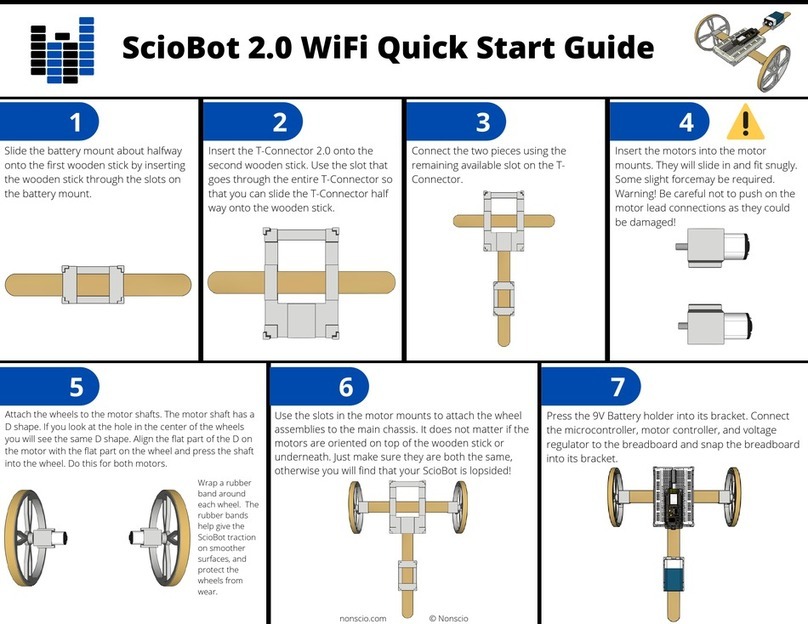
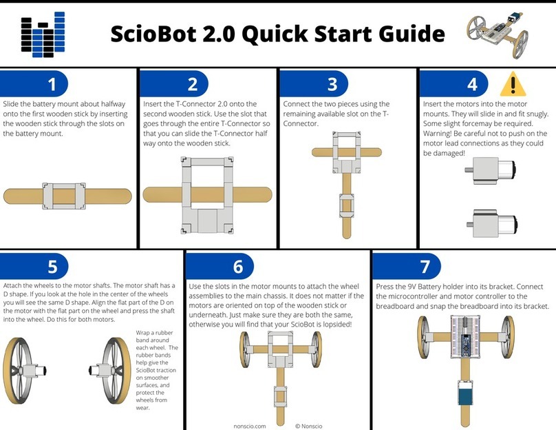
Slide the battery mount about halfway onto the first wooden stick by inserting the wooden
stick through the slots on the battery mount.
Step 2:
Insert the T-Connector onto the second wooden stick. Use the slot that goes through the
entire T-Connector so that you can slide the T-Connector half way onto the wooden stick.
Step 3:
Connect the two pieces using the remaining available slot on the T-Connector.
Required Parts and Components:
•2x DC Motors!
•2x Motor Mounts!
•2x ScioBot Wheels!
•2x Rubber Bands
Step 2:
Attach the wheels to the motor shafts. The motor shaft has a D shape. If you look at the
hole in the center of the wheels you will see the same D shape. Align the flat part of the D
on the motor with the flat part on the wheel and press the shaft into the wheel. Do this for
both motors.
Step 1:
Insert the motors into the motor mounts. They will slide in and fit snugly. Some slight force
may be required. Warning! Be careful not to push on the motor lead connections as
they could be damaged!
www.nonscio.com ©Nonscio 2020"
2

iii. Finalize the chassis assembly
iv. Install final electronics
Step 3:
Wrap a rubber band around each wheel. The grooves on the rim of the wheel will help you
align it in the center. It doesn’t need to be perfect! The rubber bands help give the ScioBot
traction on smoother surfaces, and protect the wheels from wear.
Required Parts and Components:
•2x Completed wheel assemblies!
•1x Completed main chassis
Step 1:
Use the slots in the motor mounts to attach the wheel assemblies to the main chassis. It
does not matter if the motors are oriented on top of the wooden stick or underneath. Just
make sure they are both the same, otherwise you will find that your ScioBot 1.0 is
lopsided!
Required Parts and Components:
•1x AA Battery Holder!
•1x Mini Breadboard
Step 1:
Clip the AA Battery holder into the battery bracket. Orientation of the wires does not
matter. Just make sure they are able to reach the T-Connector where we will install the mini
breadboard.
www.nonscio.com ©Nonscio 2020"
3

v. Wire the ScioBot 1.0
Step 2:
Press the mini breadboard into the the top of the T-Connector. Make sure the side with the
25 holes is facing up. Check to make sure the wires from the battery holder can be
plugged into the breadboard. If they are too far away, rotate the battery holder so that the
wires are pointing towards the breadboard.
Introduction:!
When following these wiring instructions, do not worry which wires you use. You will not harm your ScioBot by
connecting wires incorrectly. (Just don’t connect the positive and negative leads from the battery connector! This will
short out your batteries and drain them almost instantly) Once all the wires are connected and the ScioBot is powered
on, it may not behave as expected if the wires are not connected in the required configuration for forward travel. This
is ok because there are actually many different wiring configurations you can use to make your ScioBot behave in
different ways. You may have actually already configured your ScioBot in an advanced configuration! If you want to
ensure you have the correct wire polarity, refer to the Expert Tip in Section III before continuing. We will learn how to
adjust the wiring configuration once we have completed the wiring section!!
Breadboard:!
Every row of holes in the breadboard going from the left to right can be considered a component rail. What this means
is anything connected to a given row will be connected to all other components connected in that same row.!
DC Motors:!
A DC motor will rotate in a direction respective to the direction of current applied. It does not matter which motor lead
gets the positive current and which gets negative current, only that one is positive, and the other is negative. By
reversing the flow of current, the DC motor will rotate in the opposite direction. You can reverse the flow of current by
switching the position of the motor leads in the breadboard.
Step 1:
Connect one lead from the left motor to the top row on the
breadboard.
www.nonscio.com ©Nonscio 2020"
4

Step 6:
Connect the other lead from the battery holder to the top row
on the breadboard
Step 7:
Insert the two AA batteries into the battery holder and your
ScioBot will start running!!
Remember, the motors will ultimately rotate in a direction
respective to the direction current is applied. If the motor does
not rotate in the direction you intended, just switch the
position of the motor leads. !
For example, if the left motor rotates backwards when you
give thenScioBot power, simply switch the positions of top left
motor lead and the bottom left motor lead.!
www.nonscio.com ©Nonscio 2020"
7

Section IV. Summary
Congratulations on completing the ScioBot 1.0 build! Enjoy your robot and experiment with different wiring
configurations to learn how different applications of electric currents affect the operation of DC motors. You
have also learned the basics of using a breadboard to prototype an electronics project. Breadboards are an
essential tool when working and experimenting with electronics and engineering. By giving you the
opportunity to easily reconfigure, upgrade, and extend your prototypes, breadboards accelerate your ability to
complete projects.
EXPERT TIP:
On the back side of each motor there is a + sign. This
allows you to identify the polarity of each motor.
Applying a positive current to the + side of each motor
will cause them to rotate in the same direction. While
this is the case in a testing environment, because our
motors are facing 180˚ from each other, this will cause
the wheels to rotate in opposite directions. In order to
know that the wheels will rotate in the same direction,
we must connect the + lead from one motor and the -
lead from the other motor to the same row on the
breadboard.
www.nonscio.com ©Nonscio 2020"
10
Table of contents
Other Nonscio Robotics manuals
Popular Robotics manuals by other brands
Parrot
Parrot Jumping Sumo quick start guide
Robotis
Robotis Comprehensive Kit Robot Series quick start
SuperDroid Robots
SuperDroid Robots MLT-JR Assembly and operation
Dobot
Dobot Magician User Manual Instruction and Precautions

Zimmer
Zimmer Match LWR50L-21 Series Installation and operating instructions
Patton Robotics
Patton Robotics ESRA II Assembly and operation instructions


