NookBox KP-35 User manual

1NookBox Installation Guide Remote Keypad KP-35
Remote Keypad
(KP-35)
Installation Guide

2NookBox Installation Guide Remote Keypad KP-35
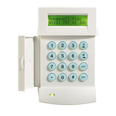
KP-35ZBS is a ZigBee Remote Keypad. It is designed to have quick access control of the
ZigBee network coordinator or system control panel. The Keypad can send wireless signals to
and receive wireless signals from the coordinator in the ZigBee network. The LCD display will
display any information the ZigBee network coordinator or system control panel sends back.
The Keypad can either be mounted on a at surface or wall mounted with the use of the 4
mounting knockouts. It also has a tamper protection switch which will be activated upon any
attempt of unauthorized opening of the cover.
The Keypad utilizes ZigBee technology for wireless signal transmission. ZigBee is a wireless
communication protocol that is reliable and has low power consumption and high transmissi-
on eciency. Based on the IEEE802.15.4 standard, ZigBee allows a large amount of devices to
be included in a network and coordinated for data exchange and signal transmission
The Keypad serves as an end device in the ZigBee network. It can be included in the ZigBee
network to transmit signal upon activation, but cannot permit any other ZigBee device to join
the network through the Keypad.
Remote Keypad
(KP-35)

3NookBox Installation Guide Remote Keypad KP-35
Identifying the parts
1. Backlit LCD Display
2. Green LED
-OFF: in stand-by mode
-ON: when any key is pressed to wake up the Remote Keypad
3. Yellow LED
-The Yellow LED will ash once every 3 seconds when any fault situation
is detected, and turn to OFF when all fault conditions are restored.
4. Backlit Numeric Keys
5. Key
6. Key
7. Backlit OK Key
-To conrm the keyed-in data or conrm the selection
8. Backlit Key
-Use this key for deleting a digit, canceling the selection, aborting
the current screen and returning to the previous screen etc
9. Backlit Arm/ Key
-Use this key to move the cursor and scroll the display upwards.
10. Backlit Arm/ Key
-Use this key to move the cursor and scroll the display downwards.
11. Buzzer
12. Battery Compartment
13. Tamper Switch
14. Bracket Holes
15. Mounting Holes
16. Bottom Fixing Screw x1
1 7. Bracket for Desktop Deployment
#
*

4NookBox Installation Guide Remote Keypad KP-35
Features
Battery and Low Battery Detection
• The Remote keypad uses three CR123 3V Lithium batteries as its power source.
• The Keypad will detect battery status. If the battery voltage is low, a Low Battery signal will be sent to the ZigBee
network coordinator or system control panel.
• When changing batteries, after removing the old batteries, press the Tamper Switch twice to fully discharge
before inserting new battery
Power Saving Feature
• When idle, Remote Keypad is in Stand-by mode and uses no power. It will activate and wake-up when any key is pressed.
• User Menu: After 5 seconds without pressing either Arm key or Home Arm key, the power goes o and it returns to Stand-by
mode.
• Enter PIN Code: After 5 seconds of key inactivity, the power goes o and it returns to Stand-by mode.
• Mode Change: After 30 seconds without receiving any signal from the Control Panel, the power goes o and it returns to
Stand-by mode.
• Upon completion of a command input, the power goes o and Remote keypad returns to Stand-by mode.
• If the Control Panel has not received the signal from the Remote Keypad for a preset period of time, the Control Panel will
consider the Remote Keypad out of order and react according to panel setting.
Tamper Protection
• The device is protected against attempts to open the back cover with a tamper switch. When the back cover is opened, it will be
triggered and the Keypad will transmit a tamper open signal to the ZigBee network coordinator or system control panel.
• After replacing the back cover. The Keypad will transmit a signal to the ZigBee network coordinator or system control panel.
• When the Keypad is properly mounted with back cover screwed onto the wall, removing the keypad forcefully will break o the
back cover from the hollowed section around the screw location and activate tamper switch.
ZigBee Network Setup
ZigBee Device Guideline
ZigBee is a wireless communication protocol that is reliable, has low power consumption and has high transmission eciency. Based on the
IEEE802.15.4 standard, ZigBee allows a large amount of devices to be included in a network and coordinated for data exchange and signal
transmission.
Due to the fundamental structure of ZigBee network, the device will actively seek and join network after powering on. Since performing a task
in connecting network may consume some power, it is required to follow the instructions to avoid draining battery of a ZigBee device.
- Ensure your ZigBee network router or coordinator is powered on before inserting battery into the ZigBee device.
- Ensure the ZigBee network router or coordinator is powered on and within range while a ZigBee device is in use.
- Do not remove a ZigBee device from the ZigBee network router or coordinator without removing the battery from a ZigBee device.
Joining the ZigBee Network
As a ZigBee device, the Keypad needs to join a ZigBee network to transmit and receive signal. Please follow the steps below to join the device
into the ZigBee network.
1. Insert the batteries.
2. Activate the Keypad by pressing the # Key, then press and hold the OK key for 10 seconds, release the button when the Keypad emits
1 beep and the LCD display shows a “Keypad will reset in 2 seconds” message. The Keypad will reset and scan for an existing ZigBee
network. Please make sure to enable the permit-join feature on the router or coordinator of your ZigBee network.
3. After joining the ZigBee network, the Keypad will emit 2 beeps and it will be registered in the security system in the network automa
tically. Please check the ZigBee network coordinator, system control panel, or CIE (Control and Indicating Equipment) to conrm if
joining and registration is successful.
4. The Keypad will not emit any sounds if it did not join the ZigBee network. Please check your ZigBee network coordinator, control
panel or CIE setting to ensure the permit-join function is available, and then use the Factory Reset function below to join the ZigBee
network.

5NookBox Installation Guide Remote Keypad KP-35
Removing Device from ZigBee Network
To remove the Keypad from current ZigBee network, the Keypad must be put to Factory Reset to complete device removal. Factory Reset
function will clear the Keypad of its stored setting information and prompt the Keypad to search for new ZigBee network.
Before removing device, make sure the Keypad is within current ZigBee network signal range.
1. Delete the Keypad from current control panel / CIE.
2. Press and hold the OK key for 10 seconds, then release the button to reset Keypad.
3. Upon reset, the Keypad will clear current ZigBee network setting and transmit signal to ZigBee coordinator to remove itself from
current ZigBee network. It will then actively search for available ZigBee network again and join the network automatically.
Using Remote Keypad with ZigBee Router
IMPORTANT NOTE
If the Remote keypad installation location is away from your system control panel and requires ZigBee routers to improve signal strength. DO
NOT use a ZigBee Router without backup battery. A ZigBee router without battery will be powered down during AC power failure and the
Remote keypad connected to the router will lose connection with ZigBee network. You should plan your Remote keypad installation location
using only ZigBee router with backup battery.
Operation
When the Keypad is under power saving mode, apply your hand to the Keypad to wake up the device. The LCD display will display the status
of the system then prompt you to “Enter PIN Code”
You must enter a Control Panel User PIN Code to proceed.
User PIN Code: Enter the User PIN Code programmed in the system control panel and press OK to conrm.
User Menu
• The Keypad will communicate with the system to retrieve information before entering User Menu.
• The system is always automatically disarmed upon entering Keypad User Menu.
• The Keypad will exit User Menu automatically after 30 seconds of inactivity.
Away Arm:
Select “Arm” and press OK key to conrm. If the ZigBee network coordinator or system control panel is successfully armed, the Re
mote Keypad will emit a long beep and the LCD will display “Away Armed”.
Home Arm:
Select “Home” and press OK key to conrm. If the ZigBee network coordinator or system control panel is successfully armed, the
Remote Keypad will emit 3 beeps and the LCD will display “Home Armed”.
Alarm Memory:
This option will become available after an alarm has been triggered. Entering the Keypad’s User Menu will be directed to the Alarm
Memory option automatically. Press OK to conrm and use and key to view the alarm memory.
Fault:
This option will only become available if fault event exists in system. To view fault events, select “Fault Display” and press OK key to
conrm. Use the and keys to view the fault events and press key to return to menu.
If you try to arm the system when fault event exists, the arming will be prohibited and the LCD screen will jump to Fault Display.
Please go to your ZigBee coordinator or system control panel to check and remove the fault condition(s). If you want to force arm the
system, select Arm or Home Arm and press OK again. The system will ignore the fault event and enter your selected arm mode.
Log:
Select “Log” and press OK key to view system log. Use the and keys to view the events and press key to return to User Menu
Setting:
Select “Setting” and press OK key to enter setting menu. Use the and keys to select setting options and press key to return to User
Menu.

6NookBox Installation Guide Remote Keypad KP-35
Beep Control:
- Entry/Exit Beep: Set to “Turn On” or “Turn O” this function to program whether the Keypad should emit warning beeps during Entry
Delay or Exit Delay timer.
- Alarm Beep: Set to “Turn On” or “Turn O” this function to program whether the Keypad should emit warning beeps when an alarm is
activated
Panic Alarm:
Select to enable or disabled the dual key panic alarm function.
Fire Alarm:
Select to enable or disabled the dual key re alarm function.
Medical Alarm:
Select to enable or disabled the dual key medical alarm function.
Quick Arm:
Select to enable the quick arm function. When enabled, the user can directly enter Away Arm or Home Arm mode without entering user
PIN code.
Press key to exit User Menu.
Mode Change Function
• After entering the PIN code, press Arm key to enter “Away Armed” mode. “Away Armed” will be displayed on the LCD screen
along with long beeping sound indicating successful operation.
• After entering the PIN code, press Home Arm key to enter “Home Armed” mode. “Home Armed” will be displayed on the LCD
screen along with 3 beeps indicating successful operation.
• After entering the PIN code, press OK key to enter “System Disarmed” mode. “System Disarmed” will be displayed on the LCD
screen along with 2 beeps indicating successful operation.
• “Counting Down” will be displayed on the LCD screen along with 1 beep every second when the system begins to countdown Exit/
Entry Delay.
• “Operation Error” will be displayed on the LCD screen along with 2 beeps indicating unsuccessful operation.
• “Fault Display” will be displayed on the LCD screen along with 3 beeps indicating arming fault.
• “Incorrect PIN Code” will be displayed on the LCD screen along with 4 beeps indicating incorrect password submission.
NOTE:
• After 30 seconds without receiving any signal from the Control Panel, the power goes o and it returns to Stand-by mode.
• If submitting incorrect PIN Code for 5 times within 10 minutes, the Remote Keypad will be automatically locked up for 5 minutes. During
this period, any operation will be invalid. When the lockup time expires, the Remote Keypad will sound 1 long beep.
Dual Key Alarm Function
• The dual key alarm function allows user to activate alarm by pressing and holding two keys on the Keypad for 3 seconds. The functions
maybe enabled or disabled using Keypad menu and are disabled by default. The user must rst activate them in User Menu to use these
features.
• Panic Alarm: Press Button 1 + 3 to trigger a Panic Alarm.
• Fire Alarm: Press Button 4 + 6 to trigger a Fire Alarm.
• Medical Alarm: Press Button 7 + 9 to trigger a Medical Alarm.
Fault Conditions
• If the Control Panel is under “Armed Mode”, you CANNOT activate Home mode by using Remote keypad. If you do so, the Remote Key
pad will sound 2 beeps indicating the Control Panel is under Arm Mode.
• Press 4-digit PIN Code followed by Arm key or Home Arm to change mode. If there is a fault, then Remote keypad will beep 3 times. The
Yellow LED will light up when any fault situation is detected.
• If submitting incorrect PIN Code for 5 times within 10 minutes, the Remote Keypad will be automatically locked up for 5 minutes. During
this period, any operation will be invalid. When the lockup time expires, the Remote Keypad will sound 1 long beep.

7NookBox Installation Guide Remote Keypad KP-35
Change of Battery
• Put the Control Panel to programming menu to bypass the KP tamper alarm.
• Dismount the Remote keypad.
• Take out the old battery and press any key to discharge before replacing the new battery in the battery compartment,
with unmarked (negative) side of battery facing down.
• Close the case using the rear xing screws.
• Screw back the Remote keypad to the surface with mounting screws.
• Put the Control Panel back to normal operation mode.
Reset Remote Keypad to Factory Default
• The Remote Keypad can be reset to clear all learnt-in data and return all setting to default value by following procedure below:
• Please follow Change of Battery procedures for factory default.
• Enter “0000” + “#” to reset Keypad to default value.
• “Reset Default” will be displayed on the LCD screen along with 3 beeps indicating successful operation.
• All learnt-in data will be cleared.
• Entry/ Exit Beeps will be disabled.
• Alarm Beep will be disabled.
• Dual Key alarm function will be disabled.
NOTE:
• Factory default setting can only be performed within 10 seconds after inserting batteries. If the Keypad is not wake up within 10 seconds
after inserting batteries. Remove batteries and try again.
• Factory default does not aect ZigBee learning. The Keypad does not need to be relearnt again after factory default.
Mouting Remote Keypad
The Keypad is designed to be wall mounted with xing screws and plugs provided.
The bottom of the Keypad has 4 knockouts, where the plastic is thinner, for mounting purpose.
1. Break through the plastic knockouts on the base.
2. Drill 4 holes and x the screws & plugs provided.
3. Screw the base onto the wall.
4. Reattach the base and cover assembly.

8NookBox Installation Guide Remote Keypad KP-35

9NookBox Installation Guide Remote Keypad KP-35
For more information visit:
www.getnookbox.com
This manual suits for next models
1
Table of contents
Other NookBox Keypad manuals

