©Vantage, 8/16/2016 / IS-0583-B Equinox 41 LCD Keypad – MODEL: EQ41TB-TI page 1 of 4
INSTALLATION
VANTAGECONTROLS.COM VANTAGE INSTALL GUIDES
2168 West Grove Parkway, Suite 300, Pleasant Grove, UT. 84062 USA
Telephone: 801 229-2800 ●Fax: 801 224-0355 Equinox 41 LCD Keypad – MODEL: EQ41TB-TI
Overview
Vantage's Equinox 41 LCD TouchScreen
has been designed to be located in the
same space as a traditional keypad,
installed in a single gang wall box.
Vantage's Equinox 41 uses self discovering
widgets, eliminating countless hours of
tedious programming. Navigate and
control, with real time feedback. Widgets
may be further personalized or additional
controls setup directly on the touchscreen,
by selecting the top right side of each
widget and moving to additional screens of control and/or
setup preferences. The interface uses intuitive gestures; swipe
left and right to change widgets, touch and release for normal
button operation, or press and hold for dim-cycle, volume
controls, etc.
Equinox 41 Features/Operations
Vertical screen orientation displays one widget per page.
Equinox platform provides built-in widgets using Vantage
proprietary auto discovery widgets for fast automatic
screen design.
Equinox 41 incorporates Vantage’s consistent user
experience interface. In-wall touchscreens, tablets and
smart phones use the same user interface.
Power over Ethernet, PoE or PoE+.
oPoE optional Ethernet 4 Port PoE Injector part
number DA2400.
Communicates over Ethernet, via Vantage Ethernet bus.
Firmware upgradable over Ethernet from Design Center.
Built-in ambient light sensor for “Active,” AUTO mode
screen brightness.
Built-in proximity activation, 6” maximum, may be
programmed to execute a task with a hand wave across
front of station.
Dual operation mechanical buttons, bottom left and right;
oleft navigates to home screen,
oright may be programmed with a task from Design
Center.
Profiles; show/hide available widgets and other personal
settings:
oShow or hide widgets*, settings are unique to the
current profile selected.
oCreate profiles for different areas, users, time of day,
etc. in a project.
*NOTE: Available widgets are dependent on system design
and drivers used in the Design Center project.
Top of screen displays:
o(left-a) icon, touch for vertical ribbon list of widgets.
o(left-b) icon for current weather conditions and
temperature, via Vantage weather service,
o(right-c) selected profile. Touch to enter Settings,
select another profile, or select another home.
Main screen automatically displays Widgets (order may be
changed in profile/settings directly from the App).
oWidgets (based on Design Center project file):
Scenes
Music
Video
Climate
Weather
Timers
Lighting
Security
Cameras
Shades
Pool and Spa
more coming
Raise/Lower dimmable loads and volume control via minus
/ plus (-/+) graphical buttons.
Graphical icons and text color track load status; orange =
ON and white = OFF.
Press and release the upper right section on each widget
for additional control and/or personalization.
Access screen settings - touch profile name (upper right).
oSelect Profiles
oSelect Settings
Edit Dashboard
Edit Options
Supported Languages
Arabic
German
English
Spanish
French
Hebrew
Italian
Japanese
Korean
Dutch
Portuguese
Russian
Chinese (simplified)
Edit Device
Edit Profiles
Station Reset – simultaneously press and hold both
mechanical buttons for about three seconds.
Station reset into service mode – simultaneously press and
hold both mechanical buttons for 10 seconds.
oService mode is automatically used when updating
firmware from Design Center.
oIf the application code is corrupt it may cause the
screen to lock, preventing Design Center from
updating or reloading the firmware. Use this option to
reboot the screen to service mode allowing Design
Center to update the corrupted firmware.
oTo manually exit server mode use the Station Reset
option (above)
Specifications
Description
Specification
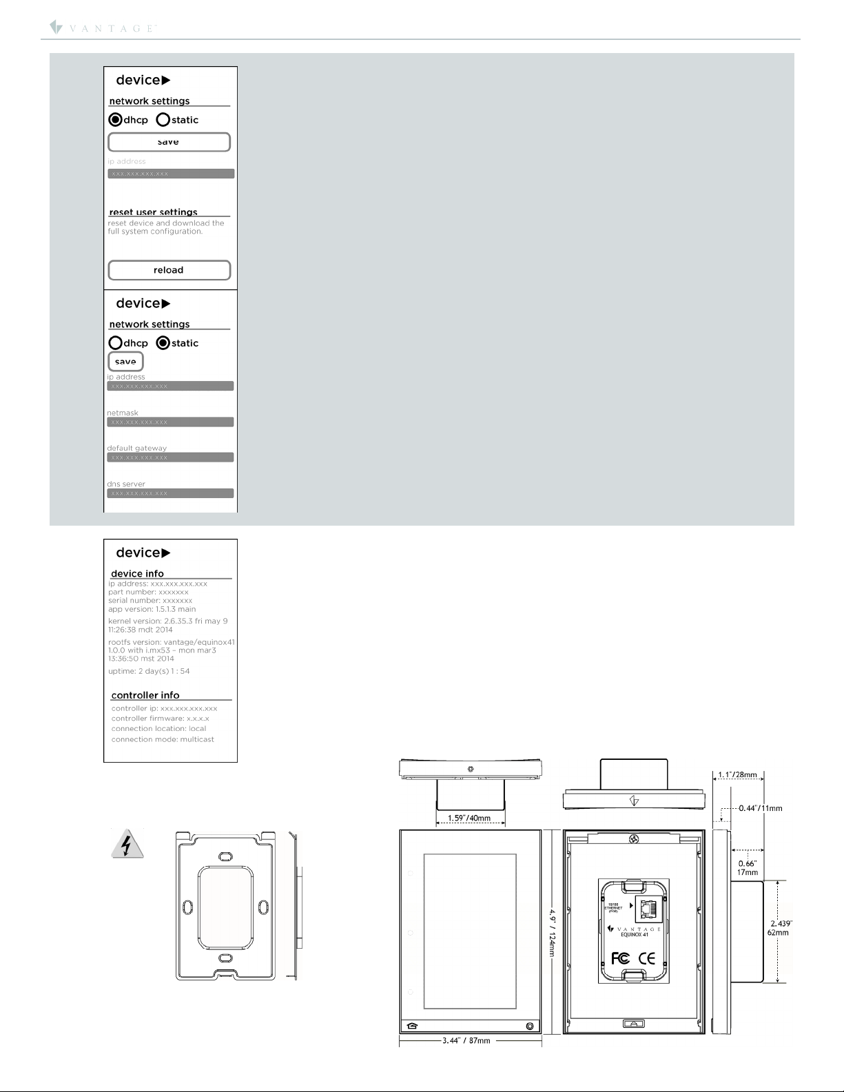
Dimensions,
HWD
(at wall
surface)
4.9” x 3.44” x 0.44”
124mm x 87mm x 11mm
Dimensions, HWD
(overall)
4.9” x 3.44” x 1.1”
124mm x 87mm x 28mm
Finished
Weight
8.8 oz. or 249.5g
Power
Ethernet with PoE, PoE+, 5W
Wiring Connections Communication & Power:
PoE/PoE+ via Ethernet RJ45
Surge Suppression
Yes
Maximum Gangs
Single Gang Only
LCD Button Status
Automatic (white = off, orange
= on)
Mounting US/European style, single gang, wall boxes or
low-voltage brackets
Addressing
Self addressing through software
Finish
TRIM - Titanium / TOUCHSCREEN –
Black Glass
Glass Surface
Chemically Strengthened
Ambient Operating
Temperature
32-95°F -or- 0-35°C
Ambient Operating
Humidity
5-95% non-condensing
CE/FCC Compliance
Yes
Widgets Overview
For detailed information about all widgets and other profile
and settings screens, click on file link below to load Widget
Instructions: LINK: Equinox Widgets_install.pdf
System Requirements
Equinox 41 is compatible with InFusion Design Center version
3.3 software or higher. For new projects it is recommended
that firmware and software be kept to the most current
release.
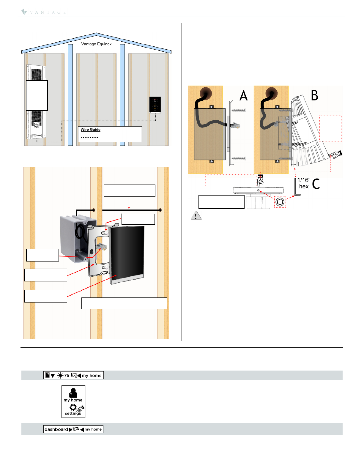
Installation
Installation of Vantage products should be performed or
supervised by a Certified Vantage Installer. The Vantage
Equinox 41 TouchScreen installs into US/European style, single
gang, wall boxes or low-voltage brackets. Connect to local
network via PoE/PoE+ RJ45 Ethernet connection.