Nooploop TOFSense-M User manual

TOFSense-M User Manual V1.4
Language: English
Firmware: V1.0.6
NAssistant: V4.4.0
Product Series: TOFSense-M,TOFSense-M S

Copyright © Nooploop LTd 2023. All Rights Reserved. Content
Content
Content .............................................................................................................................................. 2
Disclaimer ..........................................................................................................................................3
1Introduction ................................................................................................................................... 5
2UART Output ................................................................................................................................ 5
2.1 Active Output .................................................................................................................... 5
2.2 Query Output ..................................................................................................................... 5
3Can Output .....................................................................................................................................6
3.1 Active Output .................................................................................................................... 6
3.2 Query Output ..................................................................................................................... 6
4NAssistant Operations ................................................................................................................... 7
4.1 Firmware Update ............................................................................................................... 7
4.2 Record, Replay and Export ................................................................................................8
5Pixel ...............................................................................................................................................9
6FOV ............................................................................................................................................. 10
7Cascade Ranging ......................................................................................................................... 10
8Protocol Unpack .......................................................................................................................... 10
8.1 Introduction ..................................................................................................................... 10
8.2 Example ........................................................................................................................... 11
8.2.1 NLink_TOFSense_M_Frame0 ............................................................................ 11
8.2.2 NLink_TOFSense_Read_Frame0 ....................................................................... 12
8.2.3 NLink_TOFSense_CAN_Frame0 ....................................................................... 12
8.2.4 NLink_TOFSense_CAN_Read_Frame0 ............................................................. 13
9FAQ ............................................................................................................................................. 13
10 Reference ...................................................................................................................................16
11 Abbreviation and Acronyms ......................................................................................................16
12 Update Log ................................................................................................................................ 16
13 Further Information ................................................................................................................... 16

Disclaimer
Copyright © Nooploop LTd 2023. All Rights Reserved.
3
Disclaimer
Document Information
Nooploop reserves the right to change product specifications without notice. As far as possible
changes to functionality and specifications will be issued in product specific errata sheets or in new
versions of this document. Customers are advised to check with Nooploop for the most recent updates
on this product.
Life Support Policy
Nooploop products are not authorized for use in safety-critical applications (such as life support)
where a failure of the Nooploop product would cause severe personal injury or death. Nooploop
customers using or selling Nooploop products in such a manner do so entirely at their own risk and
agree to fully indemnify Nooploop and its representatives against any damages arising out of the use of
Nooploop products in such safety-critical applications.
Regulatory Approvals
The TOFSense series sensors, as supplied from Nooploop currently have the following laser
product certifications. Users need to confirm whether these certifications are applicable according to
the region where such products are used or sold. All products developed by the user incorporating the
TOFSense series sensors must be approved by the relevant authority governing radio emissions in any
given jurisdiction prior to the marketing or sale of such products in that jurisdiction and user bears all
responsibility for obtaining such approval as needed from the appropriate authorities.

Disclaimer
Copyright © Nooploop LTd 2023. All Rights Reserved.
4
Certification Description:
The TOFSense series products comply with the Class 1 standard specified in IEC 60825-1:2014
Edition 3.
1. Caution - Use of controls or adjustments or performance of procedures other than those specified
herein may result in hazardous radiation exposure.
2. According to IEC 60825-1:2014 Safety of laser products - Part 1:Equipment classification and
requirements. The maximum output laser power of the product is 50.5uW.
The TOFSense series products comply with the Class 1 laser product standard specified in GB
7247.1-2012.
1. Attention: Improper use of the control or adjustment device, or failure to follow each step of the
operation may result in harmful radiation exposure.
2. According to GB 7247.1-2012 Safety of laser products - Part 1: Equipment classification and
requirements, the maximum output laser power of the product is 50.5uW.
Introduction
Copyright © Nooploop LTd 2023. All Rights Reserved.
5
1Introduction
This document mainly introduces how to use the TOFSens-M and TOFSens-M S systems, as well
as the precautions that need to be taken during the usage process. You may need to refer to the
following materials for a better understanding:
TOFSense-M_Datasheet.pdf
2UART Output
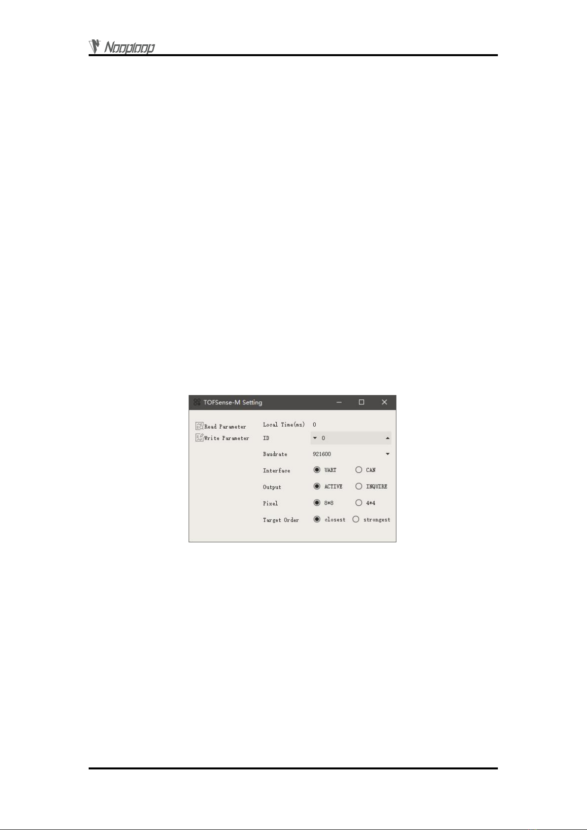
2.1 Active Output
UART active output mode can only be used in a single module. In this mode, the module actively
outputs measurement information at a fixed frequency (15Hz for 8*8 mode, 60Hz for 4*4 mode),
following the NLink_TOFSense_M_Frame0 protocol.
Connect the TOFSense-M series products to NAssistant software using a USB to TTL module
(refer to the datasheet for wire sequence and power supply voltage). After successful recognition, click
to enter the settings page, and the UART active output mode configuration is shown in Figure 1. After
configuring the parameters, click the Write Parameters button to save the parameters. After
successfully writing the parameters, you can read the parameters once to confirm whether they have
been written successfully.
Figure 1: Configuration diagram for UART active output mode
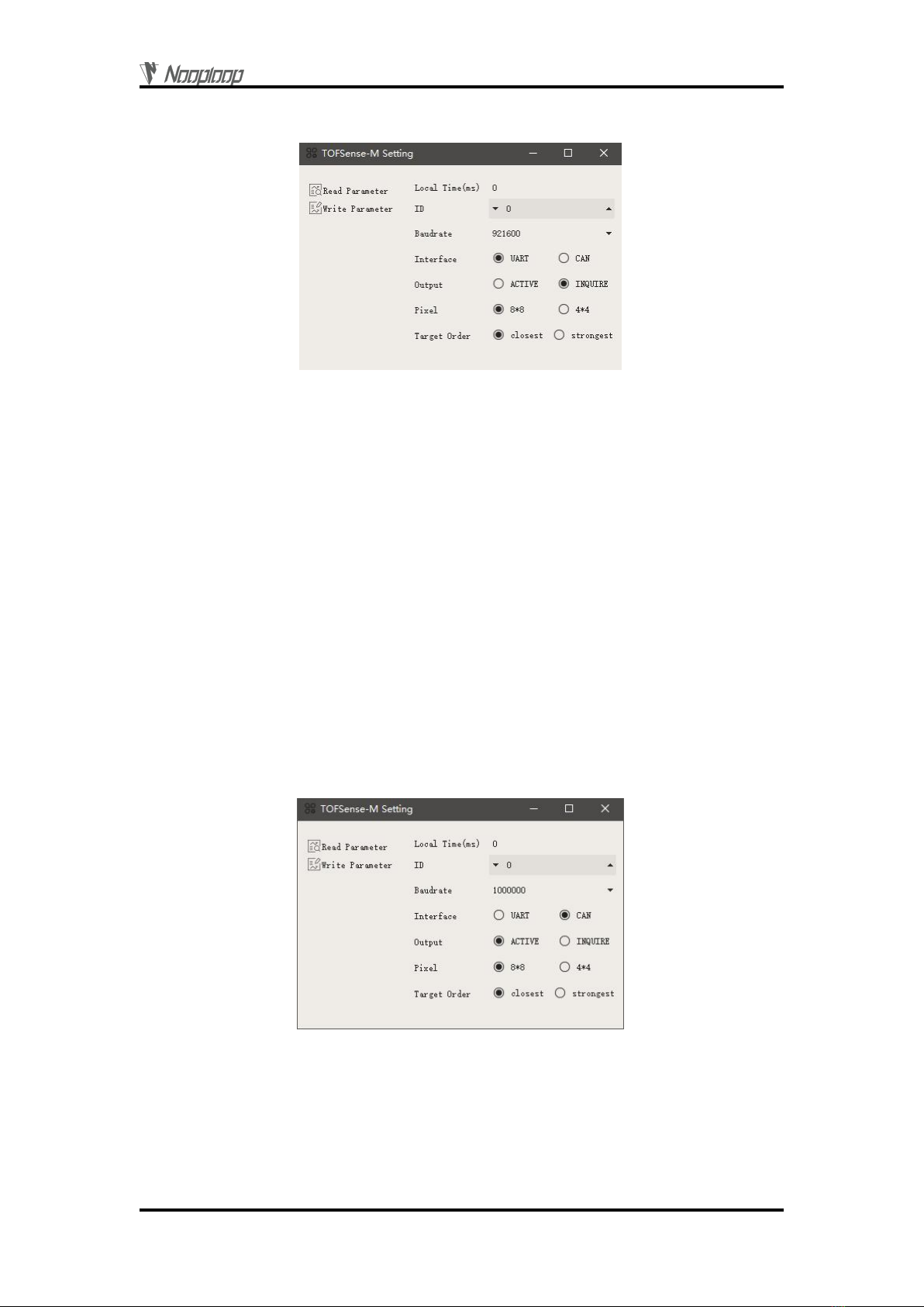
2.2 Query Output
UART query output mode can be used in single module and cascading situations. In this mode,
the controller sends a query command containing the module ID to the desired query module, and the
module outputs a frame of measurement information. The query frame format follows the
NLink_TOFSense_Read_Frame0 protocol, and the output frame format follows the
NLink_TOFSense_M_Frame0 protocol.
Connect the TOFSense-M series products to NAssistant software using a USB to TTL module
(refer to the datasheet for wire sequence and power supply voltage). After successful recognition, click
to enter the settings page, and the UART query output mode configuration is shown in Figure 2. After
configuring the parameters, click the Write Parameters button to save the parameters. After
successfully writing the parameters, you can read the parameters once to confirm whether they have
Can Output
Copyright © Nooploop LTd 2023. All Rights Reserved.
6
been written successfully.
Figure 2: Configuration diagram for UART query output mode
3Can Output
3.1 Active Output
CAN active output mode can be used in single module and cascading situations. In this mode, the
module actively outputs measurement information at a frequency of 10Hz (64 frames for 8*8 mode and
16 frames for 4*4 mode, each frame outputting ranging information for one pixel), following the
NLink_TOFSense_CAN_Frame0 protocol.
Connect the TOFSense-M series products to NAssistant software using a USB to TTL module
(refer to the datasheet for wire sequence and power supply voltage). After successful recognition, click
to enter the settings page, and the CAN active output mode configuration is shown in Figure 3. After
configuring the parameters, click the Write Parameters button to save the parameters. (If you have
previously switched to CAN mode and cannot recognize it directly, you need to follow the FAQ
method (M power on while holding the button, M S send serial command) to configure it to UART
mode first and then change the parameters.)
Figure 3: Configuration diagram for CAN active output mode
3.2 Query Output
CAN query output mode can be used in single module and cascading situations. In this mode, the
controller sends a query command containing the module ID to the desired query module, and the
module outputs the measurement information of all pixel points of the module (64 frames for 8*8 mode,

NAssistant Operations
Copyright © Nooploop LTd 2023. All Rights Reserved.
7
16 frames for 4*4 mode). The query frame format follows the NLink_TOFSense_CAN_Read_Frame0
protocol, and the output frame format follows the NLink_TOFSense _CAN_Frame0 protocol.
Connect the TOFSense-M series products to NAssistant software using a USB to TTL module
(refer to the datasheet for wire sequence and power supply voltage). After successful recognition, click
to enter the settings page , and the CAN query output mode configuration is shown in Figure 4.
After configuring the parameters, click the Write Parameters button to save the parameters. (If you
have previously switched to CAN mode and cannot recognize it directly, you need to follow the FAQ
method (M power on while holding the button, M S send serial command) to configure it to UART
mode first and then change the parameters.)
Figure 4: Configuration diagram for CAN query output mode.
4NAssistant Operations
4.1 Firmware Update
Firmware upgrade requires a computer with internet access to install the NAssistant software. The
firmware is mainly divided into two types: public version firmware and test version firmware.
The steps for firmware update, reflash, and downgrade are as follows:
1.Click the firmware update button on the software's main page to enter the firmware update
page. It will automatically load the latest public version firmware (you can also click "Public Version
Firmware" to load the latest public version firmware after switching to other firmware). Click "Test
Version Firmware" and enter the firmware test code obtained from Nooploop's official website in the
pop-up window. Click "OK" to load the corresponding test version firmware.
2.Click the "Firmware Update" button to update the firmware (if the firmware version of the
module currently connected by NAssistant is lower than or equal to the loaded firmware version, then
the "Firmware Update" button will be grayed out and cannot be clicked. In this case, you need to click
the "Ignore Version" button first to downgrade or reflash with the same version).
3.Wait for the progress bar to reach 100 and the page to return to normal from grayed out.
Confirm whether the firmware version displayed on the main page is consistent with the loaded
firmware version. If it is consistent, it means the update was successful.

NAssistant Operations
Copyright © Nooploop LTd 2023. All Rights Reserved.
8
Figure 5: Firmware update page schematic diagram
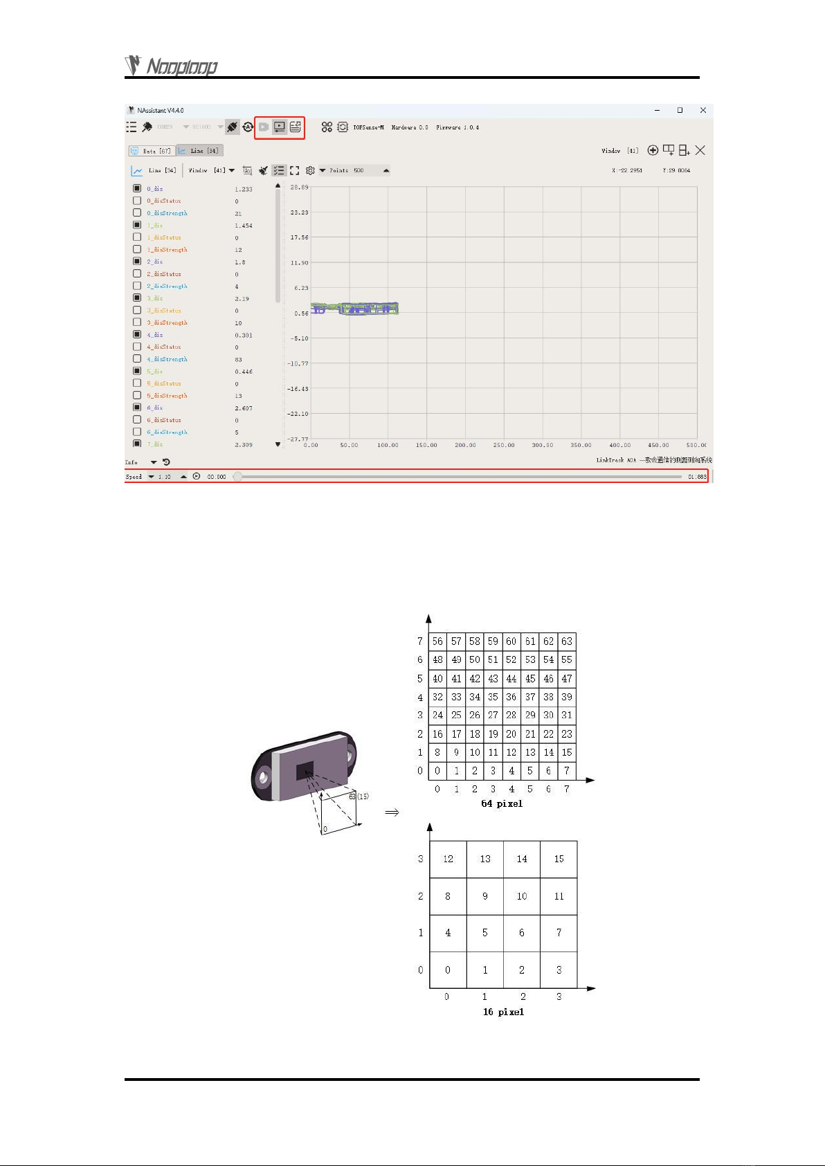
4.2 Record, Replay and Export
NAssistant provides a convenient data recording, playback, and export function. Users can click
the button on the main page menu bar to start real-time raw data recording, and click the button
again to stop recording and output the *.dat file. The recorded *.dat file can be extracted by clicking the
button to open the default storage path and sent to the after-sales engineer for troubleshooting. The
software is equipped with a playback control bar, which can adjust the playback rate, progress, etc. (the
recorded data is the data received by the NAssistant software during the time between the two clicks of
the recording button).
Both real-time and playback modes can export text data to a local .xlsx file by clicking the button
. Click the button again to stop exporting and automatically open the folder where the file is located.
The exported data is the data received or played back by the NAssistant software during the time
between the two clicks of the export button.
Note: If the folder is not automatically opened, find the corresponding folder according to the log
prompt in the lower left corner of the software's main page, or click the menu button, click "Open Data
Folder", and look for it in the "export_data" folder.
Pixel
Copyright © Nooploop LTd 2023. All Rights Reserved.
9
Figure 6: Data recording, playback, and export.
5Pixel
The module supports 64 (8*8) and 16 (4*4) pixel output. The relationship between pixels and
actual dimensions is shown in Figure 7.
Figure 7: FOV and pixel correspondence schematic

FOV
Copyright © Nooploop LTd 2023. All Rights Reserved.
10
6FOV
The field of view (FOV) parameter represents the angle covered by the module's emitted
ranging light. The module's FOV parameter is 45 °horizontally and vertically, and 63 °
diagonally.
7Cascade Ranging
Multiple sensors can be configured with different IDs and connected in series, and the ranging
information of all sensors can be read through a single communication interface. The connection
schematic is shown in Figure 8. TOFSense MS only has one communication interface, so a converter is
required for cascading.
Figure 8: Cascade ranging diagram
Under cascade ranging, three methods are suitable: UART query, CAN query, and CAN active
output.
8Protocol Unpack
8.1 Introduction
This chapter's protocol analysis examples are based on the NLink protocol, and you can also
download the NlinkUnpack sample analysis code developed in C language from the official website,
which can effectively reduce the user's development cycle.
Based on the data situation of TOFSense-F series products, in order to represent more data with
fewer bytes, we use integers to represent floating-point numbers and transmit them through protocol
frames. Therefore, when unpacking, the actual data with the multiplier is actually a floating-point
number and needs to be divided by the multiplier indicated in the protocol.
In particular, for int24 type, we need to first convert it to int32 type. To maintain the sign, we use
the method of left shift and then divide by 256. For example, for position data, we use int24 to
represent it, and the multiplier is 1000. The parsing code is as follows:
uint8_t byte[] = {0xe6,0x0e,0x00};//Decimal value: 3.814
//uint8_t byte[] = {0xec,0xfb,0xff};//Decimal value: -1.044
int32_t temp = (int32_t)(byte[0] << 8 | byte[1] << 16 | byte[2] << 24) / 256;
float result = temp/1000.0f;
Currently, the protocol verification is mainly based on the single-byte checksum at the end of the
protocol frame. Example code:
uint8_t verifyCheckSum(uint8_t *data, int32_t length){
uint8_t sum = 0;
for(int32_t i=0;i<length-1;++i){
sum += data[i];
}
return sum == data[length-1];

Protocol Unpack
Copyright © Nooploop LTd 2023. All Rights Reserved.
11
}
8.2 Example
The document assumes a single module continuous ranging scenario.
8.2.1 NLink_TOFSense_M_Frame0
Data source: Connect the module to the host computer, configure UART as active output mode,
using NLink_TOFSense_M_Frame0 protocol. For parsing distance data, please refer to the FAQ.
Raw data: 57 01 ff 00 03 a0 00 00 40 e0 81 07 00 9f 00 f0 43 03 00 58 00 c0 c8 03 00 55 00 90
e2 00 00 44 00 d0 84 00 00 57 00 18 79 00 00 61 00 e8 80 00 00 7a 00 90 65 00 00 8e 00 d8 d0 01 00
27 00 e8 74 02 00 28 00 00 f4 01 00 2e 00 f8 a7 00 00 39 00 50 c3 00 00 41 00 30 75 00 00 5b 00 70
94 00 00 61 00 00 7d 00 00 9b 00 30 e0 03 00 19 00 c8 79 09 00 1a 00 28 cf 0d 00 3a 00 b0 b3 00 00
20 00 30 75 00 00 31 00 60 6d 00 00 40 00 e8 80 00 00 4b 00 d0 84 00 00 71 00 40 3c 10 00 1e 00 88
b3 0f 00 24 00 20 b9 03 00 12 00 e8 26 0f 00 34 00 f0 d2 00 00 2c 00 c8 af 00 00 30 00 58 98 00 00 3a
00 f8 a7 00 00 47 00 d8 ed 11 09 1c 00 60 84 11 00 1c 00 e0 c8 10 00 21 00 d0 a1 10 00 25 00 88 90
00 00 1c 00 e0 ab 00 00 24 00 18 79 00 00 41 00 08 cf 00 00 41 00 68 47 14 ff 0b 00 c8 b4 14 00 0e 00
20 d6 13 00 11 00 d8 e1 13 00 14 00 d0 84 00 00 1d 00 f0 6c 11 00 19 00 a0 8c 00 00 47 00 90 65 00
00 50 00 88 41 22 ff 12 00 e8 f6 16 00 07 00 80 31 17 ff 0b 00 70 10 16 00 0c 00 40 9c 00 00 20 00 f8
a7 00 00 32 00 80 bb 00 00 33 00 a0 8c 00 00 50 00 90 d6 02 ff 2c 00 b0 e1 22 ff 0b 00 40 19 01 ff 10
00 d8 d6 00 ff 11 00 28 a0 00 00 25 00 e8 80 00 00 2b 00 c8 af 00 00 25 00 90 65 00 00 3c 00 ff ff ff ff
ff ff 7d
Table 1: NLink_TOFSense_M_Frame0 Parsing table
Data
Type
Length(Bytes)
Hex
Result
Frame Header
uint8
1
57
0x57
Function Mark
uint8
1
01
0x01
reserved
uint8
1
…
*
id
uint8
1
00
0
system_time
uint32
4
03 a0 00 00
40963ms
zone map
uint8
1
40
64
data0{dis*1000,dis_statu
s,signal_strength}
{uint24,
uint8,
uint16}
6
e0 81 07
00
9f 00
492mm
0
159
…
…
…
…
…
dataindex{dis*1000,dis_s
tatus,signal_strength}
{uint24,
uint8,
uint16}
6
…
…
…
…
…
…
…
data63{dis*1000,dis_stat
us,signal_strength}
{uint24,
uint8,
uint16}
6
90 65 00
00
3c 00
26mm
0
60
Reserved
*
6
*
*
SumCheck
uint8
1
7d
0x7d
Protocol Unpack
Copyright © Nooploop LTd 2023. All Rights Reserved.
12
8.2.2 NLink_TOFSense_Read_Frame0
Data source: Connect the module to the host computer, configure it as UART query output mode
with ID set to 0. To query data, send the following bytes from the host computer. If you need to query
modules with different IDs, simply change the ID and checksum bytes accordingly.
Raw data: 57 10 FF FF 00 FF FF 63
Table 2: NLink_TOFSense_Read_Frame0 Parsing table
Data
Type
Length (Bytes)
Hex
Result
Frame Header
uint8
1
57
0x57
Function Mark
uint8
1
10
0x10
reserved
uint16
2
…
*
id
uint8
1
00
0
reserved
uint16
2
…
*
Sum Check
uint8
1
63
0x63
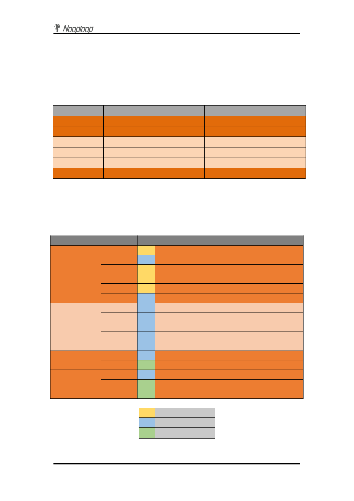
8.2.3 NLink_TOFSense_CAN_Frame0
Data source: Configure the module as CAN active output mode with ID set to 1, and connect it to
the CAN receiving device.
Raw data: StdID:0x201 + Data: e0 81 07 00 9f 00 00 FF
Table 3: NLink_TOFSense_CAN_Frame0 Parsing table
Dominant level
Dominant or recessive level
Recessive level
Field name
Part
Level
Type
Length(bits)
Hex
Result
Start Of Frame
SOF
*
1
*
*
Arbitration Field
ID
*
11
0x200+id
0x201
RTR
*
1
*
*
Control Field
IDE
*
1
*
*
r0
*
1
*
*
DLC
*
4
*
*
Data Field
dis*1000
uint24
24
e0 81 07
492mm
dis_status
uint8
8
00
0
signal_strength
uint16
16
9f 00
159
index
uint8
8
00
0
reserved
uint8
8
…
*
CRC Field
CRC
*
15
*
*
CRC_delimiter
*
1
*
*
ACK Field
ACK Slot
*
1
*
*
ACK_delimiter
*
1
*
*
End Of Frame
EOF
*
7
*
*

FAQ
Copyright © Nooploop LTd 2023. All Rights Reserved.
13
8.2.4 NLink_TOFSense_CAN_Read_Frame0
Data source: The module is configured for CAN query output mode with an ID of 1. Connect the
CAN query device, and the query device's ID (id_s) is 2.
Raw data: StdID:0x402 + Data: FF FF FF 01 FF FF FF FF
Table 4: NLink_TOFSense_CAN_Read_Frame0 Parsing table
Dominant level
Dominant or recessive level
Recessive level
9FAQ
Q1. Can it be used outdoors (in bright light) conditions?
The module is affected by natural light. Generally speaking, the stronger the natural light, the
more it will be affected, resulting in shorter ranging distance, poorer accuracy, and larger fluctuations.
In strong light conditions (such as sunlight), it is generally recommended to use the module for
short-range detection scenarios.
Q2. Is there interference between multiple modules?
When multiple modules are working at the same time, even if the infrared light emitted from one
module crosses or hits the same position as another module, it will not affect the actual measurement.
However, if two modules are at the same horizontal height and facing each other, the measurement
may be affected for both of them.
Q3. Why is there no data output from TOFSense-M?
Each module has undergone strict testing before shipping. If there is no data, please first check if
the mode, wiring (power supply voltage, wire sequence correctness, and whether the pins on both sides
of the communication are conducting as recommended by using a multimeter to test), baud rate and
Field name
Part
Level
Type
Length(bits)
Hex
Result
Start Of Frame
SOF
*
1
*
*
Arbitration Field
ID
*
11
0x400+id_s
0x402
RTR
*
1
*
*
Control Field
IDE
*
1
*
*
r0
*
1
*
*
DLC
*
4
*
*
Data Field
reserved
uint24
24
…
*
id
uint8
8
01
id = 1
reserved
uint32
32
…
*
CRC Field
CRC
*
15
*
*
CRC_delimiter
*
1
*
*
ACK Field
ACK Slot
*
1
*
*
ACK_delimiter
*
1
*
*
End Of Frame
EOF
*
7
*
*

FAQ
Copyright © Nooploop LTd 2023. All Rights Reserved.
14
other configurations are correct. For CAN output mode, please check if the bus has termination
resistors (usually 120Ω).
Q4. What should be noted during installation?
If you do not want to detect the ground or other reflective surfaces, it is necessary to avoid
obstructions within the FOV angle during installation. Additionally, the ground height should be taken
into consideration, and it is necessary to avoid obstructions such as ground reflections within the FOV.
If the installation height is close to the ground, the module can be slightly tilted upwards for
installation.
Q5. Are the module's UART, CAN, and I/O the same interface?
The UART interface and the CAN interface of the module share the same physical interface. To
switch between different communication modes, simply convert the corresponding wire sequence.
Q6. Why can't NAssistant software recognize the module after switching to CAN mode? How to
switch between different communication modes?
Currently, NAssistant software only supports recognizing modules in UART mode. In UART mode,
after successfully recognizing the module through the upper computer, you can enter the settings page
to configure the module for CAN communication mode; in CAN communication mode, TOFSense-M
needs to hold the button and power on the module. When the indicator light changes from fast flashing
to slow flashing, release the button, and the module will forcibly enter the temporary UART mode.
Then enter the settings page through the upper computer and select UART mode to write parameters;
TOFSense-M S can switch back to UART mode by sending the following serial command to the
module several times: 54 20 00 ff 00 ff ff ff ff 00 ff ff 00 10 0e ff ff ff ff ff ff ff ff ff ff ff ff ff ff ff 7b
Q7. What should be noted during firmware updates?
Do not power off or plug/unplug the USB-to-TTL during the update process. Wait for the
indicator light to change from fast flashing to slow flashing before using it normally. It is
recommended to update the firmware according to the following operations:
First, use a USB-to-TTL module to connect the TOFSense-M/MS module to NAssistant upper
computer. After waiting for successful recognition, click the settings button to change the
parameters to UART mode with a 921600 baud rate in INQUIRE query output mode, and then click
write parameters. After writing the parameters successfully, close the upper computer page, unplug the
USB-to-TTL module, reopen the new upper computer page, plug in the USB-to-TTL module again,
connect the USB-to-TTL module to the corresponding port, click recognition, and wait for successful
recognition before updating the firmware.
Q8. Does the module output the shortest distance, the longest distance, or the average distance?
The module will obtain multiple distance values within the FOV for a single measurement (64
points in 8x8 mode, 16 points in 4x4 mode) and output the distances to all points in the specified order.
Q9. How is the distance output when it is out of range?
When out of range, the distance output remains unchanged from the previous moment's value. At
this time, the distance status is 255, and you can refer to the distance status indicator for judgment.

FAQ
Copyright © Nooploop LTd 2023. All Rights Reserved.
15
Q10.What is the reason for not being able to obtain data in CAN query mode?
First, ensure that the wire sequence between CAN devices is correct. Secondly, the TOFSense-M
series ports do not include 120R matching resistors. Ensure that the query device's side resistance
matches, and finally, check whether the sent query frame format meets the
NLink_TOFSense_CAN_Read_Frame0 protocol, paying special attention to the correct standard frame
ID.
Q11. Why can't the cascaded modules in CAN mode receive data or receive incomplete data?
Cascaded modules may experience a voltage drop. Therefore, in general use, a single line is used
to connect all the modules, with the voltage decreasing for modules further down the line. If the voltage
received by later modules is lower than the minimum working voltage required for CAN mode, issues
such as not receiving data or incomplete data may occur. In this case, you can optimize in two ways:
1. use a better power supply to increase the power supply capacity.
2. use a star-shaped power supply method. For example, if you need to cascade 7 modules, first
divide the power supply into 4 outputs: the first output connects to VCC and GND of module 1 and 2,
the second output connects to VCC and GND of module 3 and 4, the third output connects to VCC and
GND of module 5 and 6, and the fourth output connects to VCC and GND of module 7. Then connect
the CAN_H and CAN_L of all 7 modules in series to the CAN bus. Testing has shown that connecting
2 modules per power supply line is the most stable. If it's a short-term test, you can connect 3 modules
per power supply line.
Q12.Why can't I enter UART configuration mode by pressing the button?
The function button is tested before shipping. If you cannot enter UART mode, try again. Note
that the button must be pressed before powering on, and released after the light slowly flashes.
Q13.What is the serial communication terminal model used by the module? What if there is no
such terminal interface on the flight controller or microcontroller?
The module uses a GH1.25 terminal. You can purchase a GH1.25 to another terminal adapter
cable or cut the included GH1.25-GH1.25 cable and solder another terminal. For wire sequence, power
supply voltage, and signal line voltage levels, please refer to the datasheet.
Q14.How to convert received e0 81 07 into distance value?
The data in the protocol frame is stored in little-endian mode and multiplied by a certain ratio
when encoded. For example, e0 81 07 is first converted to hexadecimal data 0x0781e0, which is
492000 in decimal, and divided by 1000 to get 492 millimeters.
Q15.How is the checksum calculated?
The checksum is the sum of all previous bytes and then taking the least significant byte of the
result. For example, the checksum of 55 01 00 ef 03 is 0x55+0x01+0x00+0xef+0x03=0x0148, so the
checksum is 48, and the complete data for this frame is 55 01 00 ef 03 48.
Q16.What to do if there is an error or no data when compiling the ROS driver package?
Before using the ROS driver package, users need to read the README.MD document inside the

Reference
Copyright © Nooploop LTd 2023. All Rights Reserved.
16
package and follow the steps and precautions in the document. You can also refer to the official
website's "ROS Driver Application Pictorial Tutorial" for usage.
10 Reference
[1] TOFSense-M_Datasheet.pdf
11 Abbreviation and Acronyms
Table 5: Abbreviation and Acronyms
Abbreviation
Full Title
TOF
Time of Flight
FOV
Field of View
HW
Half Wave
VCSEL
Vertical Cavity Surface Emitting Laser
12 Update Log
Table 6: Update Log
Version
Firmware Version
Data
Description
1.0
1.0.1
20211112
1. Publish the first edition of the manual
1.1
1.0.1
20220211
1. Optimize some descriptions
1.2
1.0.4
20220924
1. Add authentication-related instructions
2. Optimize some descriptions
1.3
1.0.4
20221205
1. Optimize some descriptions
1.4
1.0.6
20230404
1. Add firmware update instructions
2. Expand the FAQ and optimize some descriptions
13 Further Information
Company: SZ Nooploop Technology Co.,Ltd.
Address: A2-207, Peihong building, No. 1, Kehui Road, Science Park community, Yuehai street,
Nanshan District, Shenzhen
E-amil: marketing@nooploop.com
Website: www.nooploop.com
Table of contents
Other Nooploop Accessories manuals


