Nor-Cal Products Intellisys SoftShut TSS User manual


22
Visit our Web Site www.n-c.com
INTELLISYS SOFTSHUTTM GATE VALVE MODELS
TSS-OP-LIT 08/11
Table of Contents
Contact Nor-Cal Products
Intellisys Customer Support
at 800-824-4166
or visit our website
at www.n-c.com
List of Figures
4.1
...................Typical Installation and Configuration of a TSS-series control valve ......................................................
8
5.1
...................Exploded View of Typical TSS value assembly ....................................................................................
10
A-I .....................Controller Connection Diagrams ....................................................................................................................... 13
A-1.2 .................Pin-out Wiring Diagrams ................................................................................................................................... 14
A-1.3 .................IQA Controller ................................................................................................................................................... 14
A-1.4 .................IQD Controller ................................................................................................................................................... 15
A-II.1
................Installation Diagram for ISO-flanged TSS to OF-style ISO flange .........................................................
16
A-II.2
................Installation Diagram for ISO-flanged TSS to N-style ISO flange ..........................................................
16
A-II.3
................Installation Diagram for CF-flanged TSS to CF flange ........................................................................
16
List of Tables
2.1
...................General Equipment Specifications ......................................................................................................
4
2.2
...................TSS Reliability .....................................................................................................................................
4
2.3
...................Standard TSS-series Dimensions and Weight Specifications ................................................................
5
2.4
...................IQ-seriesTSS Dimensions and Weight Specifications ............................................................................
6
5.1
...................Recommended TSS-series Preventive Maintenance Actions and Intervals ............................................
9
5.2
...................Spare Parts and Kits Ordering Information ........................................................................................
11
5.2A
.................Spare Parts and Kits Ordering Information for valves made prior to May 2005 ...................................
11
5.3
...................Possible Failure Modes and Recommended Actions ..........................................................................
12
A-II.1
................Installation Hardware for ISO-flanged TSS to OF-style ISO flange .......................................................
17
A-II.2
................Installation Hardware for ISO-flanged TSS to N-style ISO flange.........................................................
17
A-II.3
................Installation Hardware for CF-flanged TSS to CF flange ......................................................................
17
A-III.1
...............TSS and APC Cable Assemblies and Accessories ...............................................................................
19
1.0
...................Introduction .......................................................................................................................................
3
2.0
...................Device Specification ...........................................................................................................................
4
3.0
...................Unpacking and Installation .................................................................................................................
7
4.0
...................Theory of Operation ...........................................................................................................................
8
5.0
...................Product Support ...............................................................................................................................
10
Appendix I
.......Summary Valve and Controller Connection Information ...................................................................
13
Appendix II
......Installation Hardware .......................................................................................................................
17
Appendix III
.....Valve, Accessories and Cable Assembly Ordering Information...........................................................
18
Appendix IV
.....Warranty and Intellectual Property Coverage ....................................................................................
20
Global Sales and Service
Nor-Cal Products maintains sales and
service centers in over 30 countries worldwide.
Please visit our website at www.n-c.com to
find the center nearest you.
Information in this manual is subject to change without notice.
Downloaded from Arrow.com.Downloaded from Arrow.com.

3
Call toll free 800-824-4166 or 530-842-4457 • FAX 530-842-9130
INTELLISYS SOFTSHUTTM GATE VALVE MODELS
TTSS-OP-LIT 08/11
1.0 - Introduction
NOTE: Calls attention to helpful tips about proper
installation, maintenance or use of the valve.
CAUTION: Highlights areas of concern that, if overlooked, could
result in damage to the valve or surrounding equipment.
WARNING: Alerts the installation, operating or maintenance
personnel of hazardous aspects of the valve, which, if
ignored could result in serious personal injury or death.
Thank you for purchasing a new Intellisys™ Tss SoftShut™ throttling gate valve from Nor-Cal Products. Before installing and operating the product,
please read this manual thoroughly as it contains critical hook-up and operating tips. If you encounter any problems, or if you have any questions,
please contact our Intellisys Customer Service Support at (800) 824-4166 or visit our web site at www.n-c.com.
Nor-Cal Products’ TSS Softshut gate valves are designed for foreline isolation and downstream pressure control over a wide range of vacuum control applications
in conjunction with an APC-series buried box or IQ-series on-valve controller module. The TSS Valve cannot be operated by other manufacturers’ valve
controllers. All interface and communications connections are made directly to the controller module that, in turn, provides power and position signals to the
valve motor. Used with a controller module and the inputs from one or two pressure gauges the TSS-series gate valve forms an integral part of a complete
downstream pressure control system.
Important Personnel Safety and Product Protection Information
Throughout this manual, information that is of particular importance to the installation, the safety of
operating personnel and the protection of equipment are highlighted by the following three symbols.
The WARNING symbol is also used on the equipment wherever necessary.
Downloaded from Arrow.com.Downloaded from Arrow.com.Downloaded from Arrow.com.

44
Visit our Web Site www.n-c.com
INTELLISYS SOFTSHUTTM GATE VALVE MODELS
TSS-OP-LIT 08/11
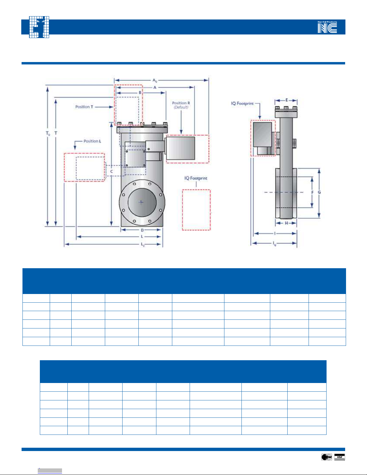
2.0 - Device Specification - General
The following figures and tables summarize specifications of the TSS-series product.
TABLE 2.1 –GENERAL EQUIPMENT SPECIFICATIONS
FEATURE SPECIFICATION
Dimensions Refer to Figures 2.1 and 2.2, as well as Tables 2.3 and 2.4
Weight, in lbs (kg) Refer to Tables 2.3 and 2.4
Rated Input 2A, 2.25Ω (only to be operated by Nor-Cal Products’ controller models)
Actuation Speed 2 sec open to closed for 2.5” – 6” valves 4 sec open to closed for 8” and 10” valves
Position Resolution 1:6,144,000 steps for 2.5” – 6” valves. 1:12,288,000 steps for 8” and 10” valves.
Leak Rate 1x10⁻⁹ atm • scc/sec He (for valves with Viton® seals)
Allowable Gate Differential Pressure 15 psi (103.4 kPa)
Heating Capabilities Body can be heated up to 305ºF (150ºC) with optional heater kits.
Protection Class I
Degree of Protection (IP) X0
Laser Class 1 (LED’s)
Certifications CE Standard for Process Equipment including EMC Directive 89/336/EC and Machinery Directive 89/392/EEC
Maximum Altitude 6562 ft (2000 m)
Allowable Ambient Operating Temperature 32ºF – 122ºF (0ºC - 50ºC)
Allowable Ambient Humidity 0 – 95% non-condensing
TABLE 2.2 – TSS RELIABILITY
SPECIFICATION COMMENTS
* MTBF > 2 million cycles or > 11,500 hours Processes with large amounts of effluent contamination or highly aggressive chemistries may reduce the MTBF
due to condensation on moving parts and/or O-ring degradation.
* Warranty 1 year
Installation Clearance For IQ-series TSSs 3” (75 mm) is required on all perforated sides. Otherwise, a minimum of 3 ½” (90 mm) is
needed on top to allow for connector(s).
Downloaded from Arrow.com.Downloaded from Arrow.com.Downloaded from Arrow.com.Downloaded from Arrow.com.
55
Visit our Web Site www.n-c.com
INTELLISYS SOFTSHUTTM GATE VALVE MODELS
TSS-OP-LIT 08/11
TABLE 2.3 – STANDARD TSS DIMENSION AND WEIGHT SPECIFICATIONS (REFER TO FIGURE 2.1)
VALVE
SIZE
NOM.
ID
TOTAL
STANDARD
WIDTH
“A”
BONNET
LENGTH
“B”
BODY
LENGTH
“C”
BODY
WIDTH
“D”
TOTAL
L-POS.
WIDTH
“L”
TOTAL
T-POS.
HEIGHT
“T”
WEIGHT
LBS (KG)
DN-63 21/210.6 (269) 5.83 (148) 11.38 (289) 4.37 (111) 12 (306) 15.7 (398) 19 (8.6)
DN-80 3 10.7 (272) 6.30 (160) 12.56 (319) 5.04 (128) 12.1 (308) 16.3 (414) 27 (12.3)
DN-100 4 11.3 (287) 7.17 (182) 14.69 (373) 5.91 (150) 12.4 (316) 18.4 (468) 36 (16.3)
DN-160 6 12.6 (321) 10.08 (256) 19.06 (226) 8.78 (223) 14.7 (372) 21.6 (549) 61 (27.7)
DN-200 8 13.9 (352) 12.40 (315) 23.39 (284) 11.14 (283) 16.4 (415) 25.4 (645) 87 (39.5)
DN-250 10 14.9 (378) 14.41 (366) 27.14 (689) 13.11 (333) 17.3 (440) 28.0 (712) 114 (52)
2.1 - Dimension Call-outs for Standard and IQ-series TSS valves (cross-reference to Tables 2.3 and 2.4)
FLANGE
TYPE
NOM.
ID
BONNET
THICKNESS
“E”
ACTUAL
I.D.
“F”
ISO
FLANGE
O.D.
“G”
CONFLAT
FLANGE
O.D.
“G”
FLANGE-
TO-FLANGE
THICKNESS
“H”
TOTAL
VALVE
HEIGHT
“T”
DN-63 21/22.64 (67) 2.76 (70) 5.35 (136) 4.45 (113) 2.76 (70) 5.5 (140)
DN-80 3 2.68 (68) 3.15 (80) 5.71 (145) CALL 2.54 (65) 5.5 (140)
DN-100 4 2.87 (73) 4.02 (102) 6.93 (176) 5.94 (151) 2.76 (70) 5.7 (144)
DN-160 6 3.07 (78) 6.02 (153) 8.86 (225) 7.99 (203) 3.15 (80) 6.1 (155)
DN-200 8 3.27 (83) 8.39 (213) 11.34 (288) 10.74 (273) 3.15 (80) 6.5 (165)
DN-250 10 3.54 (90) 10.28 (261) 13.78 (350) 12.0 (305) 3.94 (100) 7.1 (179)
Downloaded from Arrow.com.Downloaded from Arrow.com.Downloaded from Arrow.com.Downloaded from Arrow.com.Downloaded from Arrow.com.
66
Visit our Web Site www.n-c.com
INTELLISYS SOFTSHUTTM GATE VALVE MODELS
TSS-OP-LIT 08/11
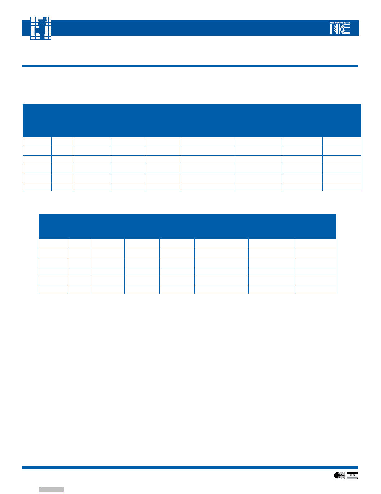
2.1 - Dimension Call-outs for Standard and IQ-series TSS valves (cross-reference to Tables 2.3 and 2.4)
TABLE 2.4 – IQ-SERIES TSS DIMENSION AND WEIGHT SPECIFICATIONS (REFER TO FIGURE 2.1)
VALVE
SIZE
NOM.
ID
TOTAL
STANDARD
WIDTH
“AQ”
BONNET
LENGTH
“B”
BODY
LENGTH
“C”
BODY
WIDTH
“D”
TOTAL
L-POS.
WIDTH
“LQ”
TOTAL
T-POS.
HEIGHT
“TQ”
WEIGHT
LBS (KG)
DN-63 21/213.4 (340) 5.83 (148) 11.38 (289) 4.37 (111) 13.3 (338) 17.7 (450) 20 (9.1)
DN-80 3 14.3 (364) 6.30 (160) 12.56 (319) 5.04 (128) 14.6 (371) 19.42 (493) 28 (12.8)
DN-100 4 13.9 (353) 7.17 (182) 14.69 (373) 5.91 (150) 14.4 (367) 20.5 (521) 37 (16.8)
DN-160 6 14.6 (373) 10.08 (256) 19.06 (226) 8.78 (223) 16.7 (423) 23.7 (603) 62 (28.2)
DN-200 8 15.8 (403) 12.40 (315) 23.39 (284) 11.14 (283) 18.4 (467) 27.4 (695) 88 (40)
DN-250 10 16.9 (428) 14.41 (366) 27.14 (689) 13.11 (333) 19.4 (492) 30.0 (762) 115 (52.5)
FLANGE
TYPE
NOM.
ID
BONNET
THICKNESS
“E”
ACTUAL
I.D.
“F”
ISO
FLANGE
O.D.
“G”
CONFLAT
FLANGE
O.D.
“G”
FLANGE-
TO-FLANGE
THICKNESS
“H”
TOTAL
VALVE
HEIGHT
“IQ”
DN-63 21/22.64 (67) 2.76 (70) 5.35 (136) 4.45 (113) 2.76 (70) 5.7 (144)
DN-80 3 2.68 (68) 3.15 (80) 5.71 (145) CALL 2.54 (64) 5.6 (142)
DN-100 4 2.87 (73) 4.02 (102) 6.93 (176) 5.94 (151) 2.76 (70) 5.9 (150)
DN-160 6 3.07 (78) 6.02 (153) 8.86 (225) 7.99 (203) 3.15 (80) 6.3 (160)
DN-200 8 3.27 (83) 8.39 (213) 11.34 (288) 10.74 (273) 3.15 (80) 6.7 (170)
DN-250 10 3.54 (90) 10.28 (261) 13.78 (350) 12.0 (305) 3.94 (100) 7.0 (178)
Downloaded from Arrow.com.Downloaded from Arrow.com.Downloaded from Arrow.com.Downloaded from Arrow.com.Downloaded from Arrow.com.Downloaded from Arrow.com.

77
Visit our Web Site www.n-c.com
INTELLISYS SOFTSHUTTM GATE VALVE MODELS
TSS-OP-LIT 08/11
Unpacking: Inspect the shipping box before unpacking. Any damage should
be reported to Nor-Cal Products or directly to the transportation carrier.
Carefully remove the product from the box and visually inspect it for damage.
NOTE: Do not discard the packing materials until the
product has been inspected to your satisfaction.
If return of the product to Nor-Cal Products should become necessary, please
contact Intellisys Customer Service to obtain a Return Materials Authorization
(RMA) Number.
Pre-Installation Functionality Check: Nor-Cal Products carefully ensures
that every product shipped is in perfect working condition. However, it is still
a good idea to quickly check the functionality of the unit prior to installation
into the vacuum system. To do so, connect the TSS-series valve to a Nor-Cal
Products APC-series controller (or directly to an appropriate DC power source
in case of an IQA or IQD-series valve). On the controller, press OPEN-OPEN-
CLOSE-CLOSE to start the valve homing sequence. The valve will complete
a 30-to-40-second initialization sequence during which the valve plate will
cycle back-and-forth a few times while the controller module OPEN/CLOSE
LEDs blink in an alternating pattern. The valve will eventually stop in the open
position.
WARNING: When working with or troubleshooting Nor-Cal
APC products extreme care must be taken to avoid putting bodily
parts in or near the valve gate mechanism or other moving parts.
These may move suddenly and unexpectedly, and many of them
are driven with sufficient force so as to cause significant harm and
possibly even dismemberment. Nor-Cal Products recommends
that a lock-out and tag-out procedure be strictly followed when
ever human physical intervention is required on all of its control
valves..
Further verification of the system can be done by toggling the “OPEN /
CLOSE” switch on the controller front/top panel. If the valve does not operate
as expected please contact Nor-Cal technical support.
Valve Installation: Install the TSS-series valve in your vacuum system using
the appropriate hardware and cables. To allow for proper ventilation and
access, make sure that at least 3” of unobstructed space is available adjacent
to all perforated sides when installing a IQA or IQD-series valve, and that at
least 3.5 inches of space is reserved above the top of the valve to allow for
cable connector hoods. A complete list of installation hardware and cables
assemblies available from Nor-Cal Products can be found in Appendices I
and II.
NOTE: Refer to the appropriate section of the Adaptive Pressure
Controller Operating Manual (APC-OP-LIT) for more details about
cable connections and pin-outs.
Once the valve is installed in the system, the approximate valve gate position
can be determined by referring to the black circular disk fastened to the rotary
shaft on the red gear box. The ut symbol represents an open valve,
whereas a closed valve is represented by the uIt symbol. Both symbols
are referenced to the small triangular mark on the gear box
3.0 - Unpacking and Installation
Heating the Valves
Heating the Valves: Sometimes it is necessary to heat the TSS-series valve
to prevent process contamination from condensing on the internal valve sur-
faces. The valve can be ordered as a heated valve, in which case the heater is
laminated to the exterior of the valve and the entire valve body is encased in a
hard insulated shell. As an alternative, Nor-Cal can offer retrofit heater jackets
that can be installed in the field. These heater jackets are available in both PID
and Thermostatically controlled versions, custom fit for each size valve. Please
call Nor-Cal Intellisys Customer Support for heater jacket and related acces-
sories ordering information.
Downloaded from Arrow.com.Downloaded from Arrow.com.Downloaded from Arrow.com.Downloaded from Arrow.com.Downloaded from Arrow.com.Downloaded from Arrow.com.Downloaded from Arrow.com.

88
Visit our Web Site www.n-c.com
INTELLISYS SOFTSHUTTM GATE VALVE MODELS
TSS-OP-LIT 08/11
4.0 - Theory of Operation
The TSS-series valve is designed for downstream pressure control. As such,
it is one of four important components in a pressure control system. The other
three essential components include a host system computer, a controller mod-
ule (APC, IQA or IQD) and one or two vacuum gauges, such as a Capacitance
Diaphragm Gauge (CDG). Most manufacturers’ vacuum gauges can be used
to provide the vacuum measurement signal, provided they have a voltage out-
put proportional to pressure. Please see Appedix I for summarized connection
information. More complete signal pin-out and communications information
can be found in Nor-Cal Adaptive Pressure Controller Operating Manual, part
# APC-OP-LIT
FIGURE 4.1 – TYPICAL INSTALLATION AND CONFIGURATION OF A
TSS-SERIES CONTROL VALVE (DASHED LINES REPRESENT TSS-IQA
OR IQD INSTALLATION)
Initialization Sequence: Before typical pressure or position control can
begin, the TSS-series valve needs to complete an initialization sequence that
lasts for approximately 30-40 seconds, depending on the size and start-
ing position of the valve. The primary purpose for this operation is for the
controller to determine the fully open and closed points, as well as for certain
motor and position calibration steps to occur. When the valve controller is
first powered on, the amber FAULT light will be illuminated and the OPEN/
CLOSE LEDs will blink in an alternating fashion. To start the initialization
sequence, press OPEN-OPEN-CLOSE-CLOSE on the controller panel. Once
the initialization sequence is complete, the valve will move to the fully open
position and the green OPEN LED will illuminate.
4. TheoryofOperation
The TSS-series valve is designed for downstream pressure control. As such, it is one of four important
components in a pressure control system. The other three essential components include a host system
computer, a controller module (APC, IQA or IQD) and one or two vacuum gauges, such as a Capacitance
Diaphragm Gauge (CDG). Most manufacturers’ vacuum gauges can be used to provide the vacuum
measurement signal, provided they have a voltage output proportional to pressure. Please see Appedix I
for summarized connection information. More complete signal pin-out and communications information
can be found in Nor-Cal Adaptive Pressure Controller Operating Manual, part # APC-OP-LIT
Vacuum
Chamber
APC Controller
Vacuum gauge(s)
Host system with RS-
232, Analog/TTL or
DeviceNet
communications
Nor-Cal TSS-series valve
Pump
Figure4.1–Typicalinstallationandconfiguration ofaTSS-seriescontrolvalve
(dashedlinesrepresentTSS-IQAorIQDinstallation)
Initialization Sequence: Before typical pressure or position control can begin, the TSS-series valve
needs to complete an initialization sequence that lasts for approximately 30-40 seconds, depending on
the size and starting position of the valve. The primary purpose for this operation is for the controller to
determine the fully open and closed points, as well as for certain motor and position calibration steps to
occur. When the valve controller is first powered on, the amber FAULT light will be illuminated and the
OPEN/CLOSE LEDs will blink in an alternating fashion. To start the initialization sequence, press OPEN-
OPEN-CLOSE-CLOSE on the controller panel. Once the initialization sequence is complete, the valve
will move to the fully open position and the green OPEN LED will illuminate.
Normal Operation: After the initialization sequence is complete normal operation of the TSS control
valve is possible. There are two primary modes of operation, a) position control mode and b) pressure
control mode.
In Position control mode the valve will move to any position in its range based on a position set-point
command from the host. The valve will remain in that position until instructed to do otherwise. Position
control mode can be useful in certain cases where pre-determined amount of baffling or throttling is
necessary.
Pressure control mode, on the other hand, is used whenever control to a specific system pressure level is
desired. The host provides the set-point value and the throttle valve strives to achieve that set point as
quickly as possible. During pressure control mode, external perturbations such as flow changes and
plasma events will automatically be compensated for by the APC, IQA or IQD controller module so that
the pressure set-point is maintained.
Part # LIT-TSS-O Contact Nor-Cal Intellisys™ Customer Support
Rev 260805.doc at 800-824-4166 ext. 186 or via the web at http:/www.n-c.com
Nor-Cal
TSS-series
Valve
Normal Operation: After the initialization sequence is complete normal
operation of the TSS control valve is possible. There are two primary modes of
operation, a) position control mode and b) pressure control mode.
In Position control mode the valve will move to any position in its range based
on a position set-point command from the host. The valve will remain in that
position until instructed to do otherwise. Position control mode can be use-
ful in certain cases where pre-determined amount of baffling or throttling is
necessary.
Pressure control mode, on the other hand, is used whenever control to a spe-
cific system pressure level is desired. The host provides the set-point value and
the throttle valve strives to achieve that set point as quickly as possible. During
pressure control mode, external perturbations such as flow changes and
plasma events will automatically be compensated for by the APC, IQA or IQD
controller module so that the pressure set-point is maintained.
Tuning: All Nor-Cal controller modules contain an Adaptive Pressure Control
Algorithm that has been designed to work over a wide range of flow- and
pressure-combinations. There are therefore no “learn modes” to execute, nor
does the user have to set PID parameters. In some instances, however, vacu-
um system design may affect the closed loop pressure control time constants.
As a result, pressure control performance may at times be affected. If satisfac-
tory pressure control cannot be achieved with the Adaptive Pressure Control
Algorithm, please contact Nor-Cal Products Intellisys Customer Support.
Downloaded from Arrow.com.Downloaded from Arrow.com.Downloaded from Arrow.com.Downloaded from Arrow.com.Downloaded from Arrow.com.Downloaded from Arrow.com.Downloaded from Arrow.com.Downloaded from Arrow.com.

99
Visit our Web Site www.n-c.com
INTELLISYS SOFTSHUTTM GATE VALVE MODELS
TSS-OP-LIT 08/11
5.0 - Product Support
TSS Valve Service and Maintenance Intervals: The TSS valve was designed for long life and high reliability and, in clean environments, have been shown to
operate with a MTBF well in excess of a year of typical vacuum processing. Process chemistry, temperature and type of use do however affect the moving parts
of the valve and hence the necessary service interval. Therefore Nor-Cal Products recommends inspecting and servicing the valve on a regular basis to avoid
unexpected failures. Please refer to Table 5.1 for recommendations on TSS-series preventive maintenance and service.
TABLE 5.1 – RECOMMENDED TSS-SERIES PREVENTIVE MAINTENANCE ACTIONS AND INTERVALS
RECOMMENDED ACTION PURPOSE / WHAT TO LOOK FOR RECOMMENDED INTERVAL
With valve still installed in system and operating
normally, visually inspect the rotary indicator disk and
drive assembly.
Rotary position indicator disk may give early indica-
tions of mechanism hang-ups, especially if observed
movement is more erratic than typical. The motor
drive assembly may move back-and-forth slightly if
too much friction is present in the valve assembly
– also an early indicator of mechanism hang-ups
Weekly to monthly, initially, until a process specific service
interval has been determined for the valve.
Remove TSS control valve from system for visual inspec-
tion.
Look for process build-up. Also, inspect for areas
showing scratches in or near gate tracks. The latter
can be a sign of gate misalignment or roller wear.
Monthly, initially, until a process specific service interval has
been determined for the valve.
With controller power OFF, remove TSS motor drive
unit and inspect Oldham coupling disk (valve body can
remain installed in vacuum system)
Inspect for Oldham coupling disk wear and fit. The
presence of a whitish powder indicates disk wear.
Also, the disk should fit snugly on each of the two
hubs, and remain on even when upside down.
After 3 months of use, and then every 3 months, until a
process specific service interval has been determined.
Remove TSS control valve from system and perform leak
check across the seat and/or to atmosphere.
Determine loss of seal integrity due to process
buildup or degradation due to chemical or thermal
attack. All new valves are tested to 1 10-9 atm•scc/
sec He (Viton® seals)
Every 6 months, unless extremely high temperatures or
highly aggressive chemicals are used.
Disassemble valve body to access gate assembly, bear-
ings and O-rings. Replace seals, re-lubricate and clean
as necessary
High vacuum grease used in bearings and seals can
gradually disappear due to evaporation or chemical
attack. The O-ring seals can wear or crack due to
contamination, chemical attack or excessive heat.
Process residue can accumulate in gate tracks and
rollers, either leading to increased particle genera-
tion or ultimate seizing of the assembly.
In heated or chemically aggressive applications:
after 6 months of continuous use.
In low temperature and inert applications: after 12
months of continuous use. Or, whenever a leak is found via
leak detection.
Downloaded from Arrow.com.Downloaded from Arrow.com.Downloaded from Arrow.com.Downloaded from Arrow.com.Downloaded from Arrow.com.Downloaded from Arrow.com.Downloaded from Arrow.com.Downloaded from Arrow.com.Downloaded from Arrow.com.
1010
Visit our Web Site www.n-c.com
INTELLISYS SOFTSHUTTM GATE VALVE MODELS
TSS-OP-LIT 08/11
5.1 - Product Support
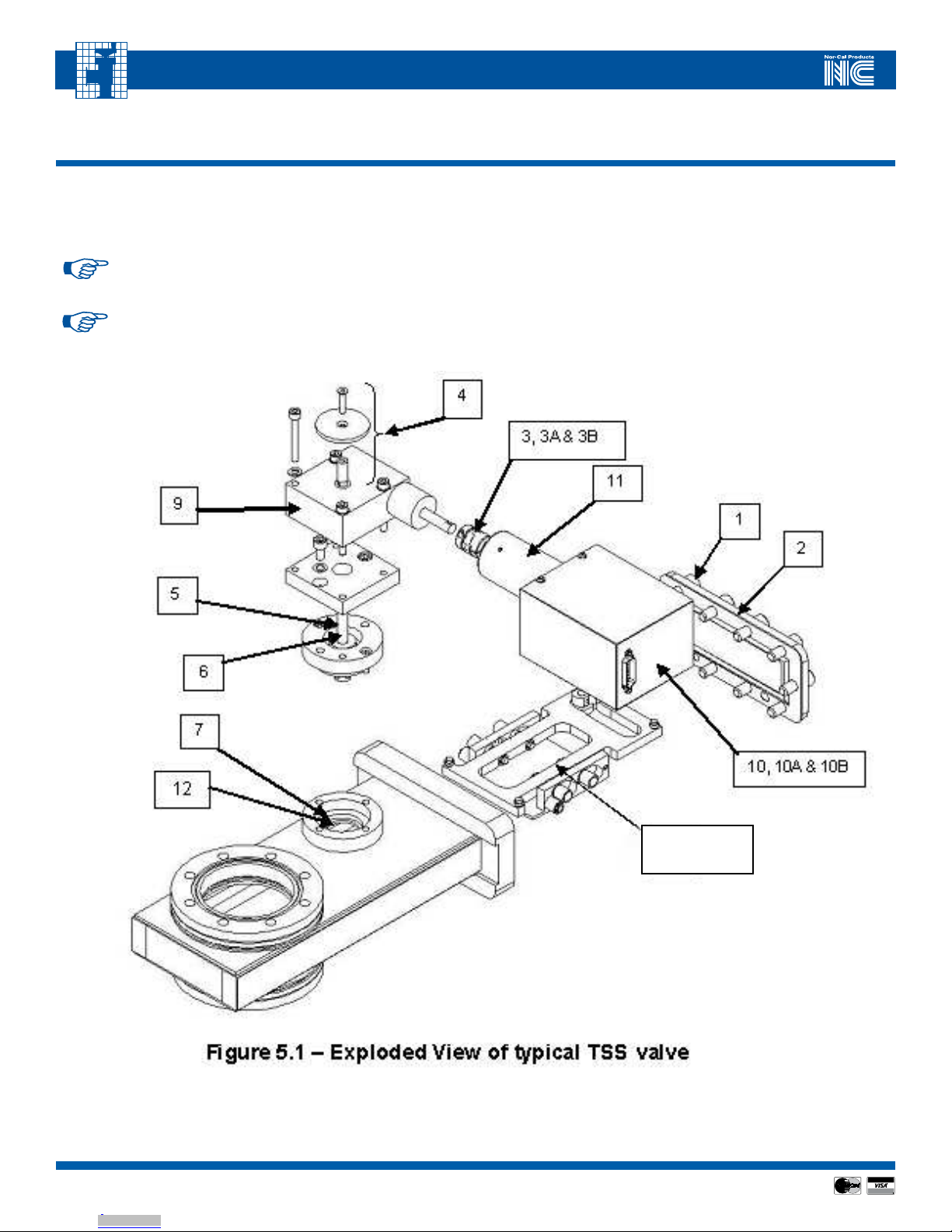
TSS Spare Parts and Kits: User serviceable parts in a TSS valve assembly generally include the items listed in Table 5.2. Please refer to the exploded view draw-
ing for illustrative purposes and call-outs. Spare parts may be ordered by contacting Nor-Cal Sales at 800-824-4166, referencing the spare part numbers in
Table 5.2
NOTE: A pressure control system issue may not be related to the throttle valve itself. Please also refer to the Adaptive
Pressure Controller Operating Manual for related troubleshooting tips and actions.
NOTE: If an operational problem does occur with the TSS control valve, please refer to the basic troubleshooting
instructions below in Table 5.3, or contact Nor-Cal Products Intellisys Customer Support at 800-824-4166 to obtain
additional instructions or a Return Materials Authorization number.
8, 8A, 8B & 8C
Downloaded from Arrow.com.Downloaded from Arrow.com.Downloaded from Arrow.com.Downloaded from Arrow.com.Downloaded from Arrow.com.Downloaded from Arrow.com.Downloaded from Arrow.com.Downloaded from Arrow.com.Downloaded from Arrow.com.Downloaded from Arrow.com.
1111
Visit our Web Site www.n-c.com
INTELLISYS SOFTSHUTTM GATE VALVE MODELS
TSS-OP-LIT 08/11
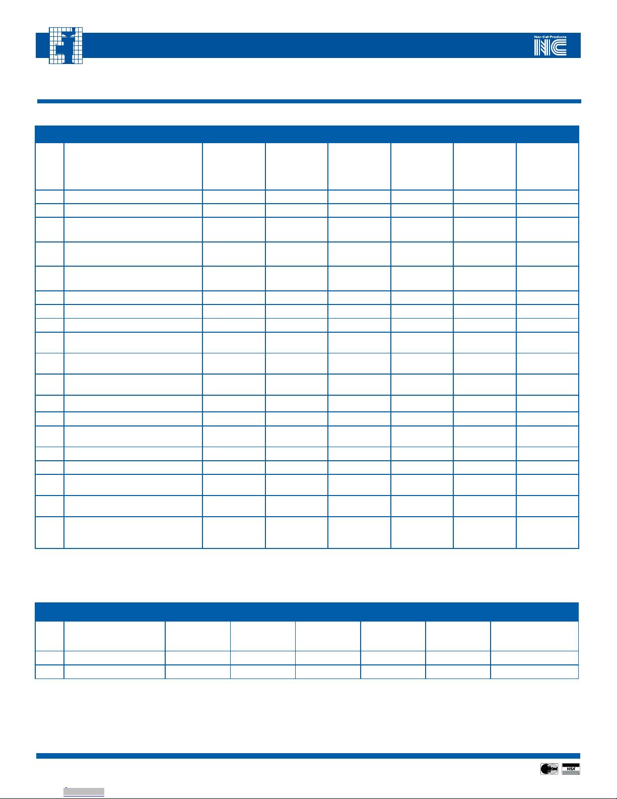
5.2 - Spare Parts and Kits Ordering Information
TABLE 5.2 – SPARE PARTS AND KITS ORDERING INFORMATION
Re f.
No. Description DN-63 DN-80 DN-100 DN-160 DN-200 DN-250
1
Bonnet bolt/washer set (one each of
M8x1.25x20 SHCS SS plus M8 Schnorr
lock washer)
TSS-BBW
(Total of 10
needed for com-
plete valve)
TSS-BBW
(Total of 12
needed for com-
plete valve)
TSS-BBW
(Total of 12
needed for com-
plete valve)
TSS-BBW
(Total of 20
needed for com-
plete valve)
TSS-BBW
(Total of 22
needed for com-
plete valve)
TSS-BBW
(Total of 28
needed for com-
plete valve)
2 Bonnet cover with Viton® o-ring TSS-63-911A TSS-80-911A TSS-100-911A TSS-160-911A TSS-200-911A TSS-250-911A
3 Oldham coupling center disk 54-310-004 54-310-004 54-310-004 54-310-004 54-310-004 54-310-004
3A Oldham hub and key for mounting to
gear box TSS-HK-GB TSS-HK-GB TSS-HK-GB TSS-HK-GB TSS-HK-GB TSS-HK-GB
3B Oldham hub and key for mounting
to motor TSS-HK-M TSS-HK-M TSS-HK-M TSS-HK-M TSS-HK-M TSS-HK-M
4* Rotary disk indicator assembly (disk
& screw) TSS-63-966A TSS-80-966A TSS-100-966A TSS-160-966A TSS-200-966A TSS-250-966A
5* Shaft Key TSS-63-962A TSS-80-962A TSS-100-962A TSS-160-962A TSS-200-962A TSS-250-962A
6* Shaft TSS-63-968A TSS-80-968A TSS-100-968A TSS-160-968A TSS-200-968A TSS-250-968A
7 Rotary Seal – Viton® TSS-63-961 TSS-80-961 TSS-100-961 TSS-160-961 TSS-200-961 TSS-250-961
8Gate and carriage assembly with
bonded Viton® seal TSS-63-925 TSS-80-925 TSS-100-925 TSS-160-925 TSS-200-925 TSS-250-925
8A Gate and carriage assembly with
replaceable Viton® seal TSS-63-925A TSS-80-925A TSS-100-925A TSS-160-925A TSS-200-925A TSS-250-925A
8B Gate (only) with replaceable Viton
seal TSS-63-925B TSS-80-925B TSS-100-925B TSS-160-925B TSS-200-925B TSS-250-925B
8C Gate O-ring Seal - Viton OR-2-232V OR-2-235V OR-2-241V OR-2-434V OR-2-444V OR-2-450V
9 Gear Box w/Oldham hub and key TSS-GB1 TSS-GB1 TSS-GB2 TSS-GB3 TSS-GB4 TSS-GB5
10 Motor Assembly w/Oldham hub and
motor mount (standard) TSS00-001 TSS00-001 TSS00-001 TSS00-001 TSS00-001 TSS00-001
10A Motor Assembly w/Oldham hub (IQA) TSSIQA-001 TSSIQA-001 TSSIQA-001 TSSIQA-001 TSSIQA-001 TSSIQA-001
10B Motor Assembly w/Oldham hub (IQD) TSSIQD-001 TSSIQD-001 TSSIQD-001 TSSIQD-001 TSSIQD-001 TSSIQD-001
11 IQ-drive motor mount (used to
change standard valve to IQ-type) TSS-XIQ-MM TSS-XIQ-MM TSS-XIQ-MM TSS-XIQ-MM TSS-XIQ-MM TSS-XIQ-MM
12 Bearing kit (includes bearing and
replacement Circlip) TSS-63-SB TSS-80-SB TSS-100-SB TSS-160-SB TSS-200-SB TSS-250-SB
N/A Shaft assembly removal tool. Helps
remove the shaft and bearing during
O-ring and valve maintenance
SD-M0014 SD-M0014 SD-M0014 SD-M0014 SD-M0014 SD-M0014
*NOTE: Effective May 2005, the Rotary disc indicator, shaft and shaft key designs changed. TSS valves are serialized using a date code followed
by a three-digit sequential number. The serial number format are the letters SS followed by the digits YYMMxxx, where YY is the year, MM is
the month and xxx is the sequential number. Please refer to Table 5.2A below for replacement parts for valves manufactured before this date.
TABLE 5.2A – SPARE PARTS AND KITS ORDERING INFORMATION FOR VALVES MADE PRIOR TO MAY 2005
Re f.
No. Description DN-63 DN-80 DN-100 DN-160 DN-200 DN-250
4
Rotary disk indicator
assembly (disk, spacer &
screw)
TSS-63-966 TSS-80-966 TSS-100-966 TSS-160-966 TSS-200-966 TSS-250-966
5 Shaft Key TSS-63-962 TSS-80-962 TSS-100-962 TSS-160-962 TSS-200-962 TSS-250-962
6 Shaft TSS-63-968 TSS-80-968 TSS-100-968 TSS-160-968 TSS-200-968 TSS-250-968
Downloaded from Arrow.com.Downloaded from Arrow.com.Downloaded from Arrow.com.Downloaded from Arrow.com.Downloaded from Arrow.com.Downloaded from Arrow.com.Downloaded from Arrow.com.Downloaded from Arrow.com.Downloaded from Arrow.com.Downloaded from Arrow.com.Downloaded from Arrow.com.

1212
Visit our Web Site www.n-c.com
INTELLISYS SOFTSHUTTM GATE VALVE MODELS
TSS-OP-LIT 08/11
5.3 - Troubleshooting
Some basic troubleshooting can be done by the user referring to the instructions and suggestions below. Table 5.3 describes possible
symptoms and recommended actions.
TABLE 5.3 – POSSIBLE FAILURE MODES AND RECOMMENDED ACTIONS
Symptom Possible Causes Recommended Action
The TSS valve does not appear to turn on or oper-
ate.
The TSS is not connected to the controller module
(standard TSS models only)
Check to make sure the controller-to-valve cable
is connected at both ends, using the correct con-
nectors.
The controller-to-valve cable is faulty (standard
TSS models only) Try another TBV-CRD-XX cable.
The controller module is not on, or is faulty. Check controller module and refer to appropriate
controller Operating Manual
The Oldham coupling is broken Turn off controller power. Remove motor drive to
inspect Oldham coupling
The TSS appears to operate but pressure- or posi-
tion control is inconsistent and poor
The valve gate is jammed or partially jammed in
the valve bore.
Turn off controller power and remove the motor
drive from the gearbox. Attempt to move
the gearbox input shaft by hand. If binding is
observed, remove valve from system to deter-
mine the root cause. Clean off process residue as
necessary using a non-abrasive method. If dam-
aged parts are found, contact Nor-Cal Intellisys
Customer Support
The Oldham coupling disk is worn or cracked
Turn off controller power. Remove drive unit from
gearbox. Replace the Oldham coupling disk as
necessary.
A whining or buzzing sound is heard from the TSS
motor drive
The Oldham coupling disk, or possibly hubs, is
loose or worn and a harmonic resonance point has
been excited
Turn off controller power. Remove drive unit from
gearbox. Replace the Oldham coupling disk as
necessary. If problem persists, contact Nor-Cal
Intellisys Customer Support.
The controller motor control coefficients have
been corrupted.
Turn off controller power. Turn back on and allow
initialization sequence to complete
The wrong controller is being used.
Note model and serial number of valve and con-
troller and contact Nor-Cal Intellisys Customer
Support
The motor and valve shaft rotate continuously in
one direction without stopping and without mov-
ing the valve gate
The square key between the rotary shaft and
gearbox is missing or broken.
Remove the rotary indicator disk, spacer and
screw. Remove the four screws holding the gear-
box to the valve. Slide off gearbox / motor assem-
bly from rotary shaft and inspect key and shaft
keyway. Replace items as necessary.
The gate actuation arm is broken or otherwise
decoupled.
Turn off vacuum system. Open the bonnet cover
by loosening the bolts on back plate. Look inside
to inspect short gate arm that links the rotary
shaft to the gate and carriage mechanism. NOTE:
It is impossible to move or turn the shaft with
the gearbox attached. If manual operation is
required, then removal of the gearbox is neces-
sary (see step above).
The valve has developed a leak to atmosphere
along the valve shaft
O-ring damage and/or loss of vacuum grease can
cause this
Follow steps above to open bonnet cover AND
remove gear head. Remove the square and plates
found under the gearbox, and remove the short
gate arm attached to the shaft. Pull shaft out
from bearing and seal cavity (this may require a
tool (Please contact Nor-Cal Intellisys Customer
Support to obtain instructions). Visually inspect
the seal, relubricate or replace as necessary.
Global Sales and Service: Nor-Cal Products maintains sales and service centers in over 30 countries worldwide. Please visit our
website at
http://www.n-c.com
to find the center nearest you.
Downloaded from Arrow.com.Downloaded from Arrow.com.Downloaded from Arrow.com.Downloaded from Arrow.com.Downloaded from Arrow.com.Downloaded from Arrow.com.Downloaded from Arrow.com.Downloaded from Arrow.com.Downloaded from Arrow.com.Downloaded from Arrow.com.Downloaded from Arrow.com.Downloaded from Arrow.com.

1313
Visit our Web Site www.n-c.com
INTELLISYS SOFTSHUTTM GATE VALVE MODELS
TSS-OP-LIT 08/11
APPENDIX I - Summary Valve and Controller Connection Information
Controller Connection Diagrams Figures A-1
CAUTION: Do not connect cables to the valve when the controller is under power.
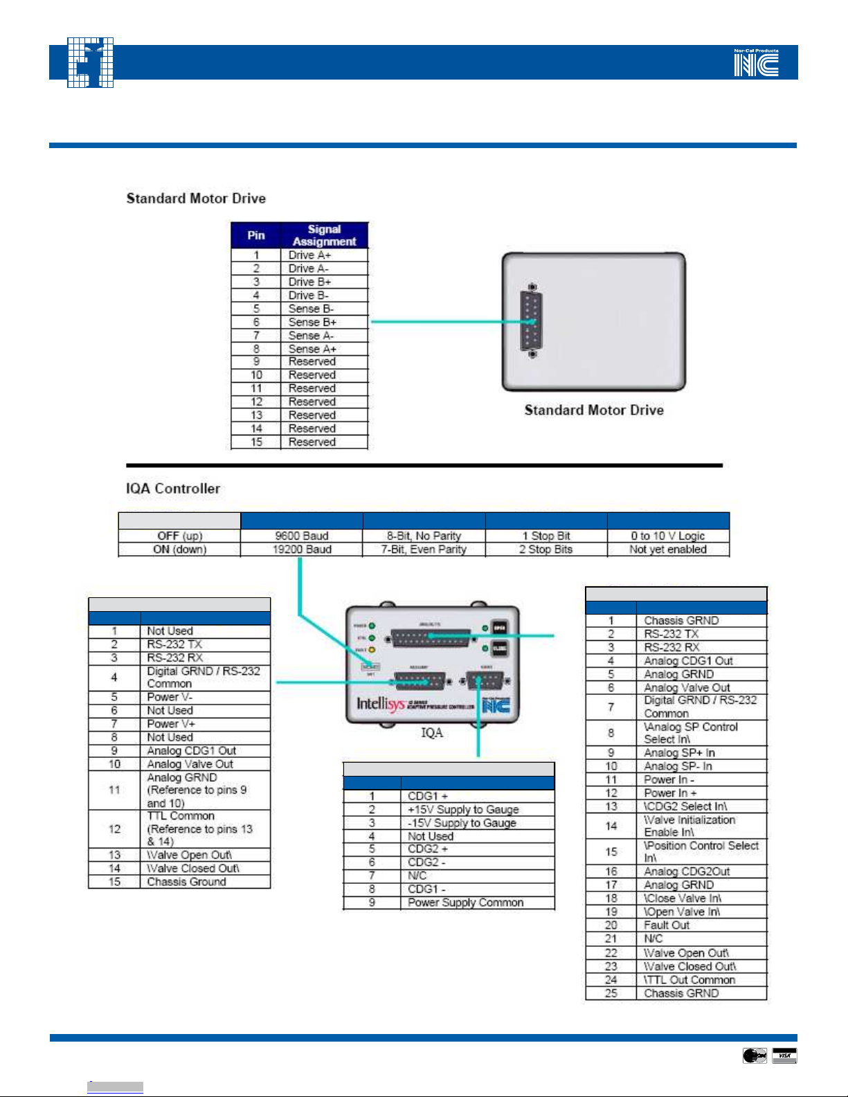
Motor Drive
For valves fitted with a motor-drive unit, connect a Nor-Cal TBV-CRD series valve cable between the motor drive and the buried-box controller.
IQA
For valves fitted with IQA controllers, first confirm that the DIPswitch settings are correct for your serial communications1, and then connect the
appropriate cables for Gauges, Auxiliary, and Analog/TTL2.
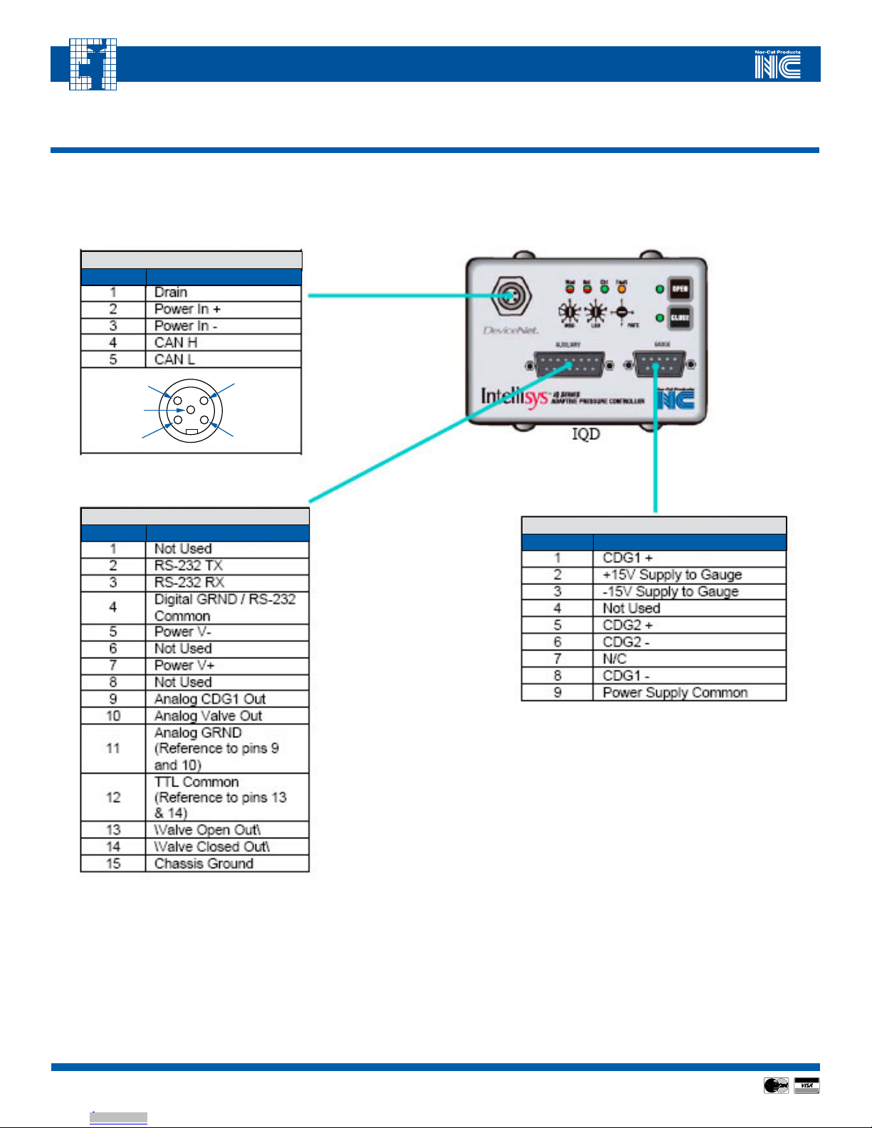
IQD
For valves fitted with IQD controllers, first confirm that the rotary DIPswitch settings are correct for your DeviceNet settings1, and then connect
the appropriate cables for Gauges, Auxiliary, Analog/TTL and/or a DeviceNet cable2.
1
IQ series DIPswitches are factory-set to default positions. Consult the IQ manual for detailed information on these settings.
2 Refer to the following section for detailed information on cabling requirements and pin-outs for IQ series accessory ports.
Downloaded from Arrow.com.Downloaded from Arrow.com.Downloaded from Arrow.com.Downloaded from Arrow.com.Downloaded from Arrow.com.Downloaded from Arrow.com.Downloaded from Arrow.com.Downloaded from Arrow.com.Downloaded from Arrow.com.Downloaded from Arrow.com.Downloaded from Arrow.com.Downloaded from Arrow.com.Downloaded from Arrow.com.
1414
Visit our Web Site www.n-c.com
INTELLISYS SOFTSHUTTM GATE VALVE MODELS
TSS-OP-LIT 08/11
APPENDIX I - Summary Valve and Controller Connection Information, Conti.
Pin-Out Wiring Diagrams
Switch 1 Switch 2 Switch 3 Switch 4
IQA DIP Switches
IQA Auxiliary Connector
Pin Signal Assignment
IQA Gauge Connector
Pin Signal Assignment
IQA Analog/TTL Connector
Pin Signal Assignment
Figure A-1.2
Figure A-1.3
Downloaded from Arrow.com.Downloaded from Arrow.com.Downloaded from Arrow.com.Downloaded from Arrow.com.Downloaded from Arrow.com.Downloaded from Arrow.com.Downloaded from Arrow.com.Downloaded from Arrow.com.Downloaded from Arrow.com.Downloaded from Arrow.com.Downloaded from Arrow.com.Downloaded from Arrow.com.Downloaded from Arrow.com.Downloaded from Arrow.com.
1515
Visit our Web Site www.n-c.com
INTELLISYS SOFTSHUTTM GATE VALVE MODELS
TSS-OP-LIT 08/11
APPENDIX I - Summary Valve and Controller Connection Information, Conti.
IQD Controller
IQD Auxiliary Connector
Pin Signal Assignment
IQD Gauge Connector
Pin Signal Assignment
IQD DeviceNet Connector
Pin Signal Assignment
4
5
1
3
2
Figure A-1.4
Downloaded from Arrow.com.Downloaded from Arrow.com.Downloaded from Arrow.com.Downloaded from Arrow.com.Downloaded from Arrow.com.Downloaded from Arrow.com.Downloaded from Arrow.com.Downloaded from Arrow.com.Downloaded from Arrow.com.Downloaded from Arrow.com.Downloaded from Arrow.com.Downloaded from Arrow.com.Downloaded from Arrow.com.Downloaded from Arrow.com.Downloaded from Arrow.com.

1616
Visit our Web Site www.n-c.com
INTELLISYS SOFTSHUTTM GATE VALVE MODELS
TSS-OP-LIT 08/11
APPENDIX II - Installation Hardware
Downloaded from Arrow.com.Downloaded from Arrow.com.Downloaded from Arrow.com.Downloaded from Arrow.com.Downloaded from Arrow.com.Downloaded from Arrow.com.Downloaded from Arrow.com.Downloaded from Arrow.com.Downloaded from Arrow.com.Downloaded from Arrow.com.Downloaded from Arrow.com.Downloaded from Arrow.com.Downloaded from Arrow.com.Downloaded from Arrow.com.Downloaded from Arrow.com.Downloaded from Arrow.com.
1717
Visit our Web Site www.n-c.com
INTELLISYS SOFTSHUTTM GATE VALVE MODELS
TSS-OP-LIT 08/11
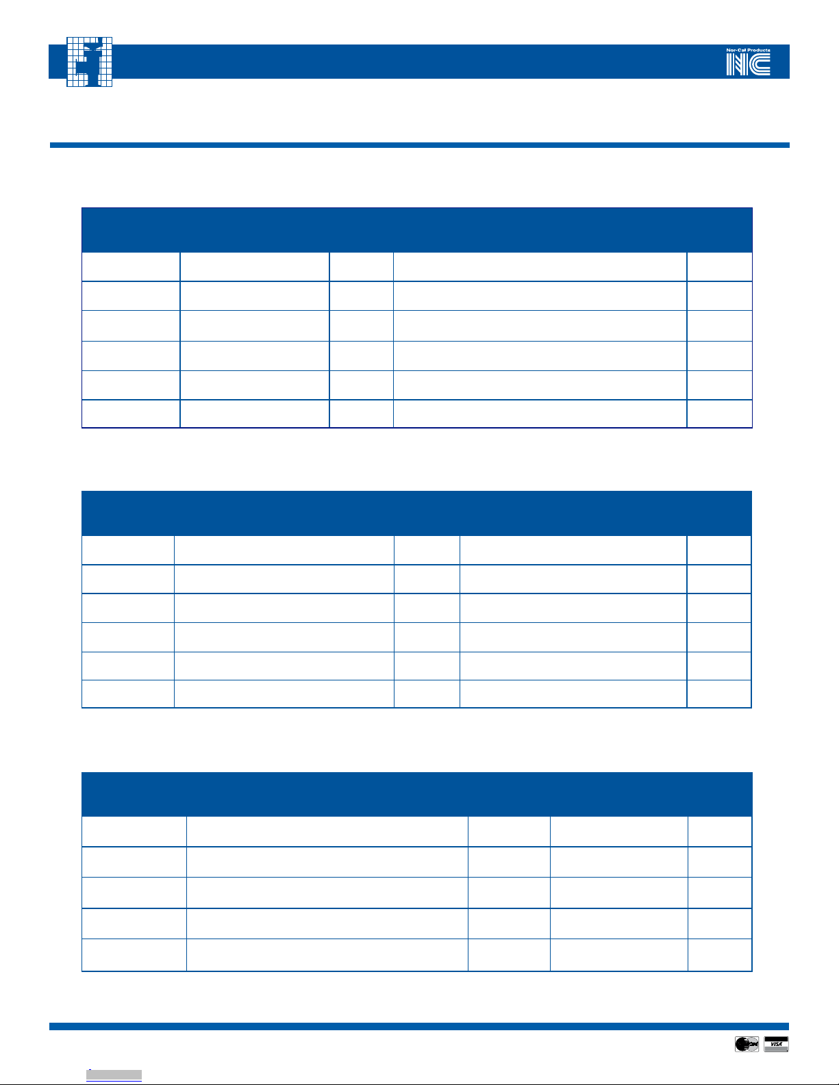
APPENDIX II - Table Install Hardware
TABLE A-II.1 – INSTALLATION HARDWARE FOR ISO-FLANGED TSS VALVES MATING TO OF-TYPE FLANGE
Valve Type
Attachment Hardware for
ISO-type valve w/OF-style
flanges (item “A”)
Required
Quantity
(per side)
Flange Viton O-ring1
(item “B”)
Required
Quantity
(per side)
TSS-(IQX)-
250-ISO-63 ISO-63-SCP-M 4 ISO-63-CR-SV, or ISO-63-CR-AV 1
TSS-(IQX)-
300-ISO-80 ISO-80-SCP-M 8 ISO-80-CR-SV, or ISO-80-CR-AV 1
TSS-(IQX)-
400-ISO-100 ISO-100-SCP-M 8 ISO-100-CR-SV, or ISO-100-CR-AV 1
TSS-(IQX)-
600-ISO-160 ISO-160-SCP-M 8 ISO-160-CR-SV, or ISO-160-CR-AV 1
TSS-(IQX)-
800-ISO-200 ISO-200-SCP-M 12 ISO-200-CR-SV, or ISO-200-CR-AV 1
TSS-(IQX)-
1000-ISO-250 ISO-250-SCP-M 12 ISO-200-CR-SV, or ISO-200-CR-AV 1
TABLE A-II.2 – INSTALLATION HARDWARE FOR ISO-FLANGED TSS VALVES MATING TO N-TYPE FLANGE
Valve Type Attachment Hardware for ISO-type
valve w/N-style flanges (item “C”)
Required
Quantity
(per side)
Flange Viton O-ring1
(item “B”)
Required
Quantity
(per side)
TSS-(IQX)-
250-ISO-63 M8 x 25mm bolt+ M8 flat washer 4 ISO-63-CR-SV, or ISO-63-CR-AV 1
TSS-(IQX)-
300-ISO-80 M8 x 25mm bolt+ M8 flat washer 8 ISO-80-CR-SV, or ISO-80-CR-AV 1
TSS-(IQX)-
400-ISO-100 M8 x 25mm bolt+ M8 flat washer 8 ISO-100-CR-SV, or ISO-100-CR-AV 1
TSS-(IQX)-
600-ISO-160 M10 x 30mm bolt+ M10 flat washer 8 ISO-160-CR-SV, or ISO-160-CR-AV 1
TSS-(IQX)-
800-ISO-200 M10 x 30mm bolt+ M10 flat washer 12 ISO-200-CR-SV, or ISO-200-CR-AV 1
TSS-(IQX)-
1000-ISO-250 M10 x 30mm bolt+ M10 flat washer 12 ISO-200-CR-SV, or ISO-200-CR-AV 1
TABLE A-II.3 – INSTALLATION HARDWARE FOR CF(M)-FLANGED TSS VALVES MATING TO CF-TYPE FLANGE
ValveType AttachmentHardwareforCF-styleflanges
(item“E”)
Required
Quantity
(perside)
FlangeCopperGasket
(item“D”)
Required
Quantity
(perside)
TSS-(IQX)-
250-CF(M)-450
B-450T (Imperial) or B-450T-M (metric):
set of 25 0.33 G-450-I 1
TSS-(IQX)-
400-CF(M)-600
B-600T (Imperial) or B-600T-M (metric):
set of 25 0.67 G-600-I 1
TSS-(IQX)-
600-CF(M)-800
B-800T (Imperial) or B-800T-M (metric):
set of 25 0.80 G-800-I 1
TSS-(IQX)-
800-CF(M)-1000
B-1000T (Imperial) or B-1000T-M (metric):
set of 25 1.00 G-1000-I 1
TSS-(IQX)-
1000-CF(M)-1200
B-1200T (Imperial) or B-1200T-M (metric):
set of 25 1.30 G-1200 1
Downloaded from Arrow.com.Downloaded from Arrow.com.Downloaded from Arrow.com.Downloaded from Arrow.com.Downloaded from Arrow.com.Downloaded from Arrow.com.Downloaded from Arrow.com.Downloaded from Arrow.com.Downloaded from Arrow.com.Downloaded from Arrow.com.Downloaded from Arrow.com.Downloaded from Arrow.com.Downloaded from Arrow.com.Downloaded from Arrow.com.Downloaded from Arrow.com.Downloaded from Arrow.com.Downloaded from Arrow.com.
1818
Visit our Web Site www.n-c.com
INTELLISYS SOFTSHUTTM GATE VALVE MODELS
TSS-OP-LIT 08/11
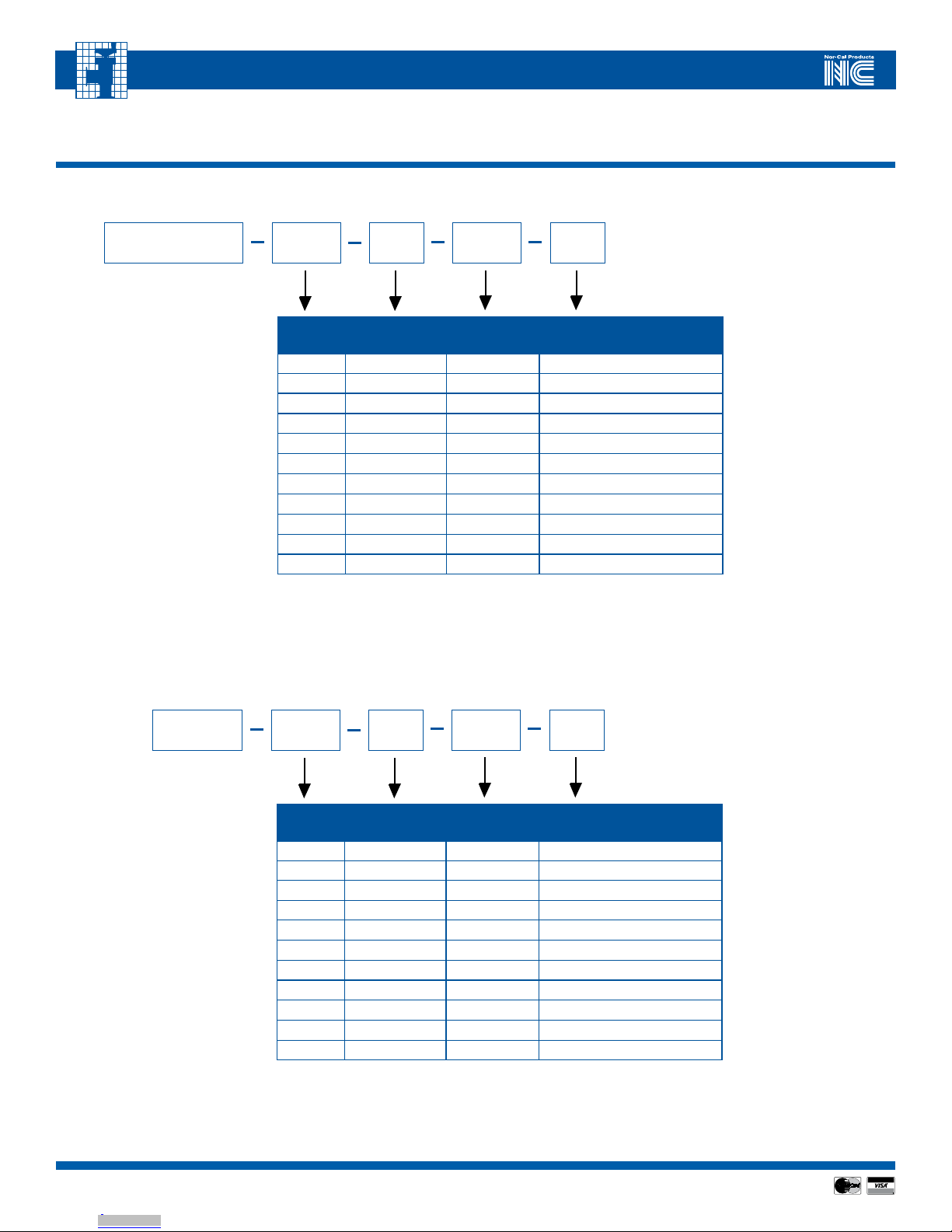
Throttling Gate Valves with IQA or IQD Control Module
Size
Family Flange Type Flange
Size O-ring Option
2
250 ISO 63 Viton (leave blank)
300 ISO 80 Perlast G74P (enter PP7)
400 ISO 100
600 ISO 160
800 ISO 200
1000 ISO 250
250 CF or CFM 450
400 CF or CFM 600
600 CF or CFM 800
800 CF or CFM 1000
1000 CF or CFM 1200
Standard Throttling Gate Valves (to be operated by a stand-alone APC-series controller)
APPENDIX III - Valve, Accessories and Cable Assembly Ordering Information
TSS- IQX1
_ _ _ _ _ _
_ _ _ _
Size
Family Flange Type Flange
Size O-ring Option2
250 ISO 63 Viton (leave blank)
300 ISO 80 Perlast G74P (enter PP7)
400 ISO 100
600 ISO 160
800 ISO 200
1000 ISO 250
250 CF or CFM 450
400 CF or CFM 600
600 CF or CFM 800
800 CF or CFM 1000
1000 CF or CFM 1200
TSS
_ _ _ _ _ _
_ _ _ _
2NOTE: Other O-ring materials are available. Call Nor-Cal Intellisys Customer Support for details
1NOTE: “X” refers to the communications mode. D = DeviceNet, A = analog, etc…
Downloaded from Arrow.com.Downloaded from Arrow.com.Downloaded from Arrow.com.Downloaded from Arrow.com.Downloaded from Arrow.com.Downloaded from Arrow.com.Downloaded from Arrow.com.Downloaded from Arrow.com.Downloaded from Arrow.com.Downloaded from Arrow.com.Downloaded from Arrow.com.Downloaded from Arrow.com.Downloaded from Arrow.com.Downloaded from Arrow.com.Downloaded from Arrow.com.Downloaded from Arrow.com.Downloaded from Arrow.com.Downloaded from Arrow.com.

1919
Visit our Web Site www.n-c.com
INTELLISYS SOFTSHUTTM GATE VALVE MODELS
TSS-OP-LIT 08/11
Cable Assemblies and Accessories
TABLE A-III.1 – TSS AND APC CABLE ASSEMBLIES AND ACCESSORIES
Description Nor-Cal Part Number
10’ (3 meter) APC controller-to-TSS valve cable TBV-CRD-10
10’ (3 meter) APC controller-to-15-pin CDG cable CDG-CRD-DB15-10
10’ (3 meter) APC controller-to-9-pin CDG cable CDG-CRD-DB9-10
10’ (3 meter) APC controller-to-flying lead CDG cable CDG-CRD-10
10’ (3 meter) APC controller-to-host RS-232 interface cable. DB-9 connector on host end APC-CRD-RS232-10
24 VDC, 3A power supply (100-240 VAC input) for IQ-series TSS. Includes AC power cord and 6’ (2 meter) DC cable with 15-pin
D-sub connector APC-PSM-DB15
10’ (3 meter) long IQD-to-host RS-232 interface cable. DB-9 connector on host end IQ-CRD-RS232-10
10’ (3 meter) long IQD-to-CDG interface cable. DB-15 connector on CDG end CDG-IQ-CRD-DB15-10
1’ (30 cm) long Y-cable used to interface two CDGs to IQD.* CDG-IQ-CRD-Y
RS-232 Service Software for Windows PC Call for details
APPENDIX III - Valve, Accessories and Cable Assembly Ordering Information
Downloaded from Arrow.com.Downloaded from Arrow.com.Downloaded from Arrow.com.Downloaded from Arrow.com.Downloaded from Arrow.com.Downloaded from Arrow.com.Downloaded from Arrow.com.Downloaded from Arrow.com.Downloaded from Arrow.com.Downloaded from Arrow.com.Downloaded from Arrow.com.Downloaded from Arrow.com.Downloaded from Arrow.com.Downloaded from Arrow.com.Downloaded from Arrow.com.Downloaded from Arrow.com.Downloaded from Arrow.com.Downloaded from Arrow.com.Downloaded from Arrow.com.

2020
Visit our Web Site www.n-c.com
INTELLISYS SOFTSHUTTM GATE VALVE MODELS
TSS-OP-LIT 08/11
Appendix IV - Limited Warranty and Intellectual Property Coverage
Products manufactured by Nor-Cal Products, Inc. (hereinafter referred to as “Nor-Cal”) are warranted against defects in material and workmanship for a
period of twelve (12) months from the date of shipment from Nor-Cal to the buyer. Any modification to the product by the buyer or their agent voids this war-
ranty. Liability under this warranty is expressly, limited to replacement or repair (at Nor-Cal ’s option) of defective parts. Nor-Cal may at any time discharge its
warranty as to any of it products by refunding the purchase price and taking back the products. This warranty applies only to parts manufactured, and labor
provided, by Nor-Cal under valid warranty claims received by Nor-Cal within the applicable warranty period and shall be subject to the terms and conditions
hereof. Expendable items such as tubes, heaters, sources, bellows, etc., by their nature may not function for one year; if such items fail to give reasonable service
for a reasonable period of time, as determined solely by Nor-Cal, they will be repaired or replaced by Nor-Cal at its election. All warranty replacement or repair
of parts shall be limited to equipment malfunctions which, in the sole opinion of Nor-Cal, are due or traceable to defects in original materials or workmanship.
Malfunctions caused by abuse or neglect of the equipment are expressly not covered by this warranty. Nor-Cal expressly disclaims responsibility for any loss or
damage caused by the use of its products other than in accordance with proper operating and safety procedures. Reasonable care must be taken by the user to
avoid hazards. In-warranty repaired or replacement parts are warranted only for the remaining unexpired portion of the original warranty period applicable to
the parts that have been repaired or replaced. After expiration of the applicable warranty period, the buyer shall be charged at Nor-Cal’s then current prices for
parts and labor plus transportation. Except as stated herein, Nor-Cal makes no warranty, expressed or implied (either in fact or by operation of law), statutory or
otherwise: and, except as stated herein, Nor-Cal shall have no liability for special or consequential damages of any kind or from any cause arising out of the sale,
installation, or use of any of its products. Statements made by any person, including representatives of Nor-Cal, which are inconsistent or in conflict with the
terms of this warranty shall not be binding upon Nor-Cal unless reduced to writing and approved by an officer of Nor-Cal. Merchandise may be returned at the
sole discretion of Nor-Cal Products, but not more than 60 days after shipment. A fee may be charged for restocking the item. An RMA number must be obtained
from Nor-Cal before returning any merchandise.
Intellectual Property Coverage
The products described in this manual are covered under U.S. Patent numbers 5,134,349; 5,202,613; 5,321,342; and 6,612,331. Additional patents are pending.
Downloaded from Arrow.com.Downloaded from Arrow.com.Downloaded from Arrow.com.Downloaded from Arrow.com.Downloaded from Arrow.com.Downloaded from Arrow.com.Downloaded from Arrow.com.Downloaded from Arrow.com.Downloaded from Arrow.com.Downloaded from Arrow.com.Downloaded from Arrow.com.Downloaded from Arrow.com.Downloaded from Arrow.com.Downloaded from Arrow.com.Downloaded from Arrow.com.Downloaded from Arrow.com.Downloaded from Arrow.com.Downloaded from Arrow.com.Downloaded from Arrow.com.Downloaded from Arrow.com.
This manual suits for next models
2
Popular Industrial Equipment manuals by other brands


ABB
ABB FSK II + Operating and maintenance manual

Pfeifer
Pfeifer 114204 Translation of the original operating manual

Martin
Martin Tornado installation instructions

Eaton
Eaton BZM1-XA Series Instruction leaflet

Craftsman
Craftsman 706.813380 Operator's manual

ACS
ACS 3200 Series Operation and instruction manual


