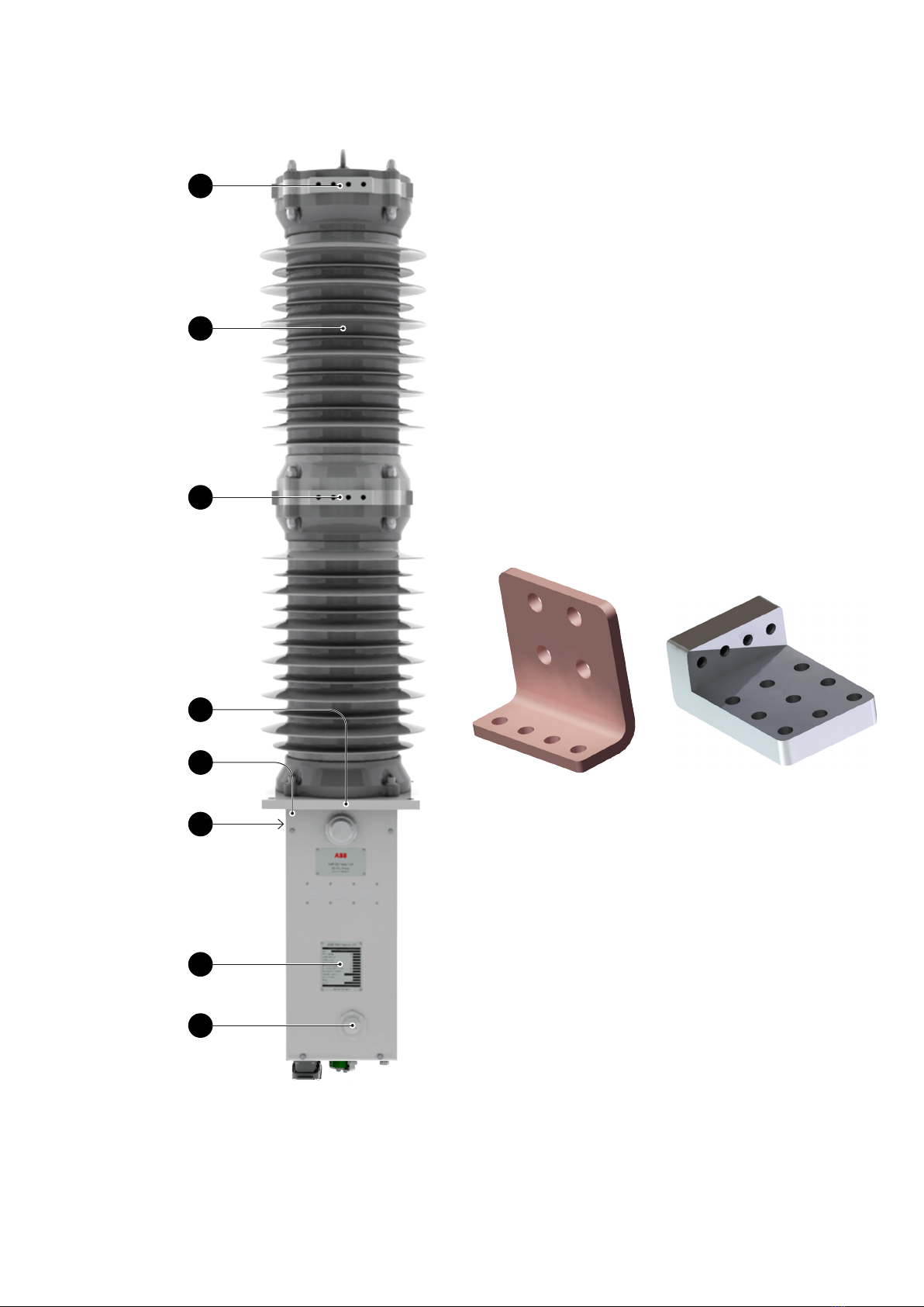
ABB FSK II + Operating instructions

—
ABB IN THE RAILWAYS – MEDIUM VOLTAGE PRODUCTS
Product Family: FSK II +
Operating and Maintenance Manual
Table of Contents
1. Disclaimer 3
2. Introduction 4
3. Product Description 5
4. Safety Precautions 11
5. Transport & Storage 12
6. Technical Data 14
7. Assembly & Commissioning 21
8. Maintenance 25
9. Disposal 29
10. Customer Service 30
11. Troubleshooting 31

PRODUCT FAMILY: FSK II + - OPERATING AND MAINTENANCE MANUAL2PRODUCT FAMILY: FSK II + - OPERATING AND MAINTENANCE MANUAL2
1VSR630206EN – en – EDO-D0002852– Instruction manual – 2021.10 Design and specification are subject to change without notice
—
Glossary
WD Watchdog function
MABS
Checksum
LBS
CB Circuit Breaker
CPU Central processing unit (on electronics card)
BI Binary input
DANGER!
personal injury!
IMPORTANT!
material damage!
—
Glossary

ABB IN THE RAILWAYS – MEDIUM VOLTAGE PRODUCTS 3
1VSR630206EN – en – EDO-D0002852– Instruction manual – 2021.10 Design and specification are subject to change without notice
—
1. Disclaimer
The information contained in this document can
corresponds to the state of technology at the time
ABB reserves the right to modify the product
further technological developments or
improvements.
Irrespective of any circumstances, the purchaser
has the responsibility to obtain information about
the maintenance conditions and special operating
requirements.
ABB cannot accept any responsibility for damages
interpretation of the information and regulations
provided in this document.
This document may neither be duplicated in its
of ABB. The transfer of the document or parts
provisions.
result from its general terms of delivery.
© ABB
—
1. Disclaimer

PRODUCT FAMILY: FSK II + - OPERATING AND MAINTENANCE MANUAL4PRODUCT FAMILY: FSK II + - OPERATING AND MAINTENANCE MANUAL4
1VSR630206EN – en – EDO-D0002852– Instruction manual – 2021.10 Design and specification are subject to change without notice
—
2. Introduction
The pictures and diagrams that are contained in
this document are intended to illustrate this
content and make it as understandable as
possible; they can differ from the contractual
content of the materials supplied through the
use of different components and elements.
2.1. Improvement Policy
placed special attention to understandability and
completeness.
It is our aim to continuously improve the quality of
communicate suggestions for improvement to
your local ABB representatives.
2.2. Notice
It is important that this document is stored in a
safe place during the entire service life of the
installation or device; it should be passed on to
ordering additional documentation, please
specify the corresponding reference number of
the document, its revision and publication date.
2.3. Standards and Regulations
2.3.1. Device
The device conforms to the provisions of the
Installations – Particular Requirements for AC
EN 50124
2.3.2. Installation and Operation
pertinent provisions are to be taken into
Regulations for the prevention of accidents of the
employer’s liability insurance associations or
comparable organisations
Safety guidelines for auxiliary and operating
materials

1
2
3
6
7
8
4
5
ABB IN THE RAILWAYS – MEDIUM VOLTAGE PRODUCTS 5
1VSR630206EN – en – EDO-D0002852– Instruction manual – 2021.10 Design and specification are subject to change without notice
—
3. Product Description
3.1. Apparatus
by their fast breaking times.
actuated mechanism instead of the conventional
mechanical spring charged mechanism. The main
insulators and the orientation of the HV terminals
can be configured according to the customer
requirements.
– EN CW004A
Connection’s range
available 1250
Connection’s range
Caption
1 Upper terminal
2 Insulator (polymer)
3 Lower terminal
4 Mounting plate
5 Cover panel
6 Drive unit
7 Identification plate
8 Access for manual tripping device (anti-clockwise direction of rotation)

1
2
3
7
7
10
8
4
5
6
9
9
8
4
1
5
2
6
3
PRODUCT FAMILY: FSK II + - OPERATING AND MAINTENANCE MANUAL6PRODUCT FAMILY: FSK II + - OPERATING AND MAINTENANCE MANUAL6
1VSR630206EN – en – EDO-D0002852– Instruction manual – 2021.10 Design and specification are subject to change without notice
—
3. Product Description
Caption
1 Valve & protection for gas filling
2 Optional cable exit
3 Position sensors ON/OFF
4 Manual tripping catch
5 Heating resistance
6 Cable exit
7 Place for contact wear check
8 Operations counter
9 Mechanical position indicator
10 Magnetic actuator
Caption
1 Control panel
2 Capacitor bank
3 MABS board
4 “READY” indication
5 “ON” pushbutton
6 “OFF” pushbutton
7 Option : Capacitor fast
discharge
8 MABS support plate
9 Terminals

Binary
inputs
supply
Binary
inputs
Output
driver
Control unit
Control panel
Capacitor
banc Magnetic
Actuator
LED
I
O
ABB IN THE RAILWAYS – MEDIUM VOLTAGE PRODUCTS 7
1VSR630206EN – en – EDO-D0002852– Instruction manual – 2021.10 Design and specification are subject to change without notice
The operation of the CB takes place by means of a
current energy for “Open” and “Close” operations
by a capacitor bank. As a result, the auxiliary
of the pole. The MABS card analyses and indicates
sensor information and given operating orders.
The MABS card repeats this indication through
auxilliary relays so that it is available for external
use.
3.1.1. MABS Control Card
buttons or remote control signals. The MABS card
permanently monitors itself, the supply voltage,
the magnetic actuator, the position sensors, the
capacitor charge and the logic of the breaker
Malfunctions are detected and signalled
the “READY
according to customer requests. These settings
are factory set and not to be changed at a later
Capacitive energy storage (capacitor bank)
Position sensors
Push button panel
LOCAL, REMOTE, GLOBAL operating modes
(explanations in later chapters)
Interlock functions (blocked in open)
System monitoring
AC/DC (depending on card type)
consumption
Autonomy for apparatus operation in case of aux.

PRODUCT FAMILY: FSK II + - OPERATING AND MAINTENANCE MANUAL8PRODUCT FAMILY: FSK II + - OPERATING AND MAINTENANCE MANUAL8
1VSR630206EN – en – EDO-D0002852– Instruction manual – 2021.10 Design and specification are subject to change without notice
—
3. Product Description
descriptions of the plug connectors.
NO changes or manipulations to the card are
to be performed without consultation with
and confirmation from ABB
KM1003 KM1004
KM1001
KM1002KM1005 KM1007
capacitor bank link
3.1.2. Add-On Card
poles and to check the consistency of their state. The
position sensors of both poles are connected via this board
to the MABS card.

ABB IN THE RAILWAYS – MEDIUM VOLTAGE PRODUCTS 9
1VSR630206EN – en – EDO-D0002852– Instruction manual – 2021.10 Design and specification are subject to change without notice
IMPORTANT!
Before connecting the portable power
supply all other auxiliary power supply shall
be disconnected or deactivated. The
rotative switch has to be in the service
position.
3.1.3. Control panel
A control panel is connected to the MABS control
pushbuttons. A READY indicator LED is underneath
the READY sign of the control panel and can be
varied according to specific customer requests,
e.g the colour scheme of the push buttons.
3.1.6. Manual opening from ground level (option)
A manual opening mechanism can be fitted onto
the breaker. With the help of an isolating hook
stick, the breaker can be opened manually from
ground level.
3.1.4. Connector for portable power supply
specific connector is accessible from the front
cover panel.
3.1.5. Mechanical position indication
A visual indication of the breaker open (green) or
close (red) can be seen from ground level. This
indication is located under the breaker.

PRODUCT FAMILY: FSK II + - OPERATING AND MAINTENANCE MANUAL10 PRODUCT FAMILY: FSK II + - OPERATING AND MAINTENANCE MANUAL10
1VSR630206EN – en – EDO-D0002852– Instruction manual – 2021.10 Design and specification are subject to change without notice
—
3. Product Description
3.1.7. Manual opening from pole level
To get access to the manual tripping catch, the
threaded plug has to be removed. This can be
removing the plug, the manual tripping crank can
be introduced into the hole in the front cover plate
and the apparatus can be tripped by counter
3.1.8. Electrical pole interlocking (option)
control box, the operation of the pole can be
blocked either in the “open” or “closed” position.
If the lever is in the “service” position, normal
operation is activated. If the lever is in the
“interlocked” position, no “remote” or “local”
Both lever positions can be locked by one or
multiple padlocks.
3.2. Identification
3.2.1. Apparatus
The identification plates are attached visibly to
the pole & control box. The position and language
can vary depending on the customer requirements
Type
designation are internal ABB descriptions and can
vary from one apparatus to another.
3.2.2. MABS Control Card
The identification of the electronic MABS card can
be done by means of the number assigned to it as
3.2.2.1. Codification Type « Barcode »
3.2.2.2. Identification of
Software
identified by a sticker attached
to the CPU and indicating the
checksum and date of the
installed programm.

ABB IN THE RAILWAYS – MEDIUM VOLTAGE PRODUCTS 11
1VSR630206EN – en – EDO-D0002852– Instruction manual – 2021.10 Design and specification are subject to change without notice
—
4. Safety Precautions
DANGER!
Any apparatus which is damaged or
defective must be switched off,
disconnected from the power network and
secured in order to avoid unintentional
operation before and during repair, which is
to be performed by qualified personnel.
DANGER!
Non-observance of the activities or
procedures identified by this symbol can
lead to personal injury!
DANGER!
This document describes the only official
procedure approved by ABB for performing
the work described. ABB refuses all
responsibility with non-observance of these
procedures.
IMPORTANT!
Non-observance of the activities or
procedures identified by this symbol can
lead to material damage!
4.1. Warning Notice
4.2. Personnel Requirements
planning, installation, disassembly, maintenance
and commissioning of the apparatus, the persons
planning
The safety before restarting and reconnection
type of apparatus and demonstrate experience on
similar types of devices. They must be capable of
reading the associated electrical diagram and
In addition they should have a thorough
electrical installations and control systems.
apparatus itself may only be performed by
suitably qualified personnel.
and avoid risks and dangers that can be caused
through electricity/chemical substances/
mechanical devices.
trained or supervised under qualified guidance,
to recognise and avoid risks and dangers that
can be caused through electricity/chemical
substances/mechanical devices.

PRODUCT FAMILY: FSK II + - OPERATING AND MAINTENANCE MANUAL12 PRODUCT FAMILY: FSK II + - OPERATING AND MAINTENANCE MANUAL12
1VSR630206EN – en – EDO-D0002852– Instruction manual – 2021.10 Design and specification are subject to change without notice
—
5. Transport & Storage
On delivery of the apparatus, its condition is to be
examined for transport damage. If a defect is
observed (including damaged packaging), the
manufacturer is to be informed immediately.
The apparatus is delivered in a vertical or
horizontal position on a Euro pallet or in a special
transport crate. With vertical transport, the
insulators are protected by a protective cover.
IMPORTANT!
During storage, the apparatus, accessories
and spare parts must remain in their original
packaging
The apparatus must be transported with
vacuum interrupter contacts in the open
position
5.1. Storage
Ensure that the apparatus, accessories and spare
parts are stored in a dry and clean place,
protected against atmospheric influences such as
dust, direct sunlight, humidity and condensation,
>30°C / 24h), long storage duration (>3month) and
presence of humidity, the resistances (in pole and
control box) must be supplied to prevent
condensation.
5.1.1. Apparatus Storage Temperatures
commissioning, completely bring the apparatus to
operating environment conditions (temperature
and humidity).
5.1.2. Orientation
The apparatus has to be stored in the original
packing and position.
5.1.3. MABS Control Card and Capacitors
Designation Value
Period of storage
procedure
Capacitors
resistance, then discharge.
MABS Control Card
Storage temperature
Relative humidity
condensation)

ABB IN THE RAILWAYS – MEDIUM VOLTAGE PRODUCTS 13
1VSR630206EN – en – EDO-D0002852– Instruction manual – 2021.10 Design and specification are subject to change without notice
IMPORTANT!
The apparatus is susceptible to blows, in
particular if equiped with ceramic insulators
Your local ABB Agent
(Address on the last page)
5.2. Transport
The apparatus and components may only be
suitable means of transportation. Shocks and
impacts, penetration of dust, liquids and moisture
are to be prevented.
To lift or move the apparatus, one should proceed
dimensions, please refer to a later chapter.
5.3. Goods Acceptance and Visual
Inspection
After delivery of the component, it is
recommended to carry out a visual inspection of
the correctness of the component
for damages
plates, the identification numbers and the
quantity of components supplied.
With subsequent longer storage, the original
protect the apparatus against environmental
influences.
5.4. Handling of transport damage
In case of ABB being responsible for transport, the
customer is required to report any damage in
within 7 days of receipt of the
goods.
Damage reports are to be directed to the

PRODUCT FAMILY: FSK II + - OPERATING AND MAINTENANCE MANUAL14 PRODUCT FAMILY: FSK II + - OPERATING AND MAINTENANCE MANUAL14
1VSR630206EN – en – EDO-D0002852– Instruction manual – 2021.10 Design and specification are subject to change without notice
—
6. Technical Data
6.1. Electrical Data Pole
6.1.1. Load break switch & Circuit breaker FSK1025
Designation
Value
Operating voltage
Number of phase
Rated voltage
Phase to earth
Across open contacts
µs)
Phase to earth
Across open contacts
Rated currents
Normal current
Short circuit making current
Rated operating sequence
CB
LBS CO
Closing time
Opening time
Strength of the circuit breaker pole Operating cycles
Strength of the vacuum interrupter
Mechanical operating cycles

ABB IN THE RAILWAYS – MEDIUM VOLTAGE PRODUCTS 15
1VSR630206EN – en – EDO-D0002852– Instruction manual – 2021.10 Design and specification are subject to change without notice
6.1.2. Circuit breaker FSK1025
Designation
Value
Operating voltage
Number of phase
Rated voltage
Phase to earth
Across open contacts
µs)
Phase to earth
Across open contacts
Rated currents
Normal current
Short circuit making current
Rated operating sequence CB
Closing time
Opening time
Strength of the circuit breaker pole Operating cycles
Strength of the vacuum interrupter
Mechanical operating cycles

6.2. MABS Control Card
Specifications are valid for cards in revision from
PRODUCT FAMILY: FSK II + - OPERATING AND MAINTENANCE MANUAL16 PRODUCT FAMILY: FSK II + - OPERATING AND MAINTENANCE MANUAL16
1VSR630206EN – en – EDO-D0002852– Instruction manual – 2021.10 Design and specification are subject to change without notice
—
6. Technical Data
The used binary inputs can differ from
project to project. Please refer to the valid
wiring diagram.
These represent the range of
values the MABS card can accept.
The specific voltage used still
needs to be selected via Dip
switches as described later.
A detailed description of the control card is
provided in a separate operating manual
and is available on special request.
6.2.1. Supply Voltages
the MABS control card.
6.2.2. Power Consumption
6.2.4. Electrical Characteristics of the Signal Inputs
6.2.3. Binary Signal Inputs
Description Value Tolerance Frequency Insulation
Galvanic,
High Voltage Galvanic,
Table 1 Supply Voltage
Power Consumption [W]
Continuous in static mode (nominal)
Maximum during the capacitor charging operation
Designation Value
Voltage range
Tolerance
Input impedance
Input current
Table 4 Characteristics of the signal inputs
Designation Description Observation
Remote Close
Remote Open
independently of the state and condition of the CPU
Standard Open or Protective trip
LOCAL
REMOTE
GLOBAL
Lock in Open Locking of apparatus in the Open position
Under Voltage (Under voltage function) Signal input for the detection of an undervoltage, variable
voltage values can be set
Table 3 Signal Inputs

ABB IN THE RAILWAYS – MEDIUM VOLTAGE PRODUCTS 17
1VSR630206EN – en – EDO-D0002852– Instruction manual – 2021.10 Design and specification are subject to change without notice
The used binary inputs can differ from
project to project. Please refer to the valid
wiring diagram.
6.2.5. Binary Signal Outputs
6.2.6. Electrical Characteristics of the Signal
Outputs
The outputs all consists of voltage free contacts
6.2.7. Output relay states
Capacitors discharged / No power supply Apparatus closed and supplied FSK-II S+ open and supplied
(open) — — —(closed)
— — —
— — —
— — —
— — — — — —
— — — — — — — — —
— — —
Table 7 States of output relays
Designation Description Observation
CB Open This output is a copy of the “OPEN” position as determined
by the sensor
CB Close
alarm
Aux. CB Open This output is a copy of the “CLOSE” position as determined
by the sensor
Aux. CB Close This output is a copy of the “CLOSE” position as determined
by the sensor
Unit Ready
WD Ready
Closed when:
not supplied
Open when:
Undervoltage detection
Closed when:
Open when:
Table 5 Signal Outputs
Designation Value
Voltage range
Max. making/breaking capacity
Max. contact resistance
Table 6 Characteristics of the signal outputs

6.2.8. Dip Switches and their function
subsequent complete discharge of capacitors.
capacitors completely discharged.
PRODUCT FAMILY: FSK II + - OPERATING AND MAINTENANCE MANUAL18 PRODUCT FAMILY: FSK II + - OPERATING AND MAINTENANCE MANUAL18
1VSR630206EN – en – EDO-D0002852– Instruction manual – 2021.10 Design and specification are subject to change without notice
—
6. Technical Data
DANGER! IMPORTANT!
6.2.8.1. I1001 Undervoltage threshold
undervoltage trip is set.
6.2.8.2. I1002 Auxiliary-OFF, HW driven Safe–OFF,
Delay On/Off, Undervoltage Behaviour
Nominal Voltage
[Un]
Tolerance Range
ON
OFF XXX
ON X
OFF X X
ON X
OFF X X
ON X
OFF X X
Auxiliary-tripping
ON
OFF X
ON X
OFF
HW driven Safe–tripping
ON
OFF X
Delay for Opening/Closing
ON X
OFF
ON
OFF X
Undervoltage Behaviour
CB Blocked in Open position
ON X
OFF

ABB IN THE RAILWAYS – MEDIUM VOLTAGE PRODUCTS 19
1VSR630206EN – en – EDO-D0002852– Instruction manual – 2021.10 Design and specification are subject to change without notice
6.2.8.3. I1004 Delay Time for Undervoltage-Trip
6.2.8.4. I1004 Operating Mode LOCAL/GLOBAL/REMOTE
6.2.8.5. I1004 Behaviour under Energy failure conditions (capacitor voltage)
Delay Time tdelay
ON
OFF XXX
ON X
OFF X X
ON X
OFF X X
ON X X
OFF X
ON X
OFF X X
ON X X
OFF X
ON X X
OFF X
ON XXX
OFF
Function
ON X
OFF LOCAL/GLOBAL
ON
OFF XLOCAL/REMOTE
Function
ON X
OFF Energy failure autotrip, active
ON
OFF XEnergy failure autotrip, inactive

6.2.9. Jumper
complete discharge of capacitors. Setting the
supply disconnected and capacitors completely
discharged.
6.2.9.1. JP1001 –Standard Open / Protection Trip
Setting of BI Y4 to “Standard Open” or “Protection
trip” input
6.2.9.2. JP1019 – EnergY CONSUMPTION
reduced during the capacitor charging time. As a
result, the charging time is extended accordingly.
PRODUCT FAMILY: FSK II + - OPERATING AND MAINTENANCE MANUAL20 PRODUCT FAMILY: FSK II + - OPERATING AND MAINTENANCE MANUAL20
1VSR630206EN – en – EDO-D0002852– Instruction manual – 2021.10 Design and specification are subject to change without notice
—
6. Technical Data
DANGER! IMPORTANT!
Function
Input active as protection trip
Input active as standard open
Table 13 Jumper 1001
Function
Standard energy consumption
ON Reduced energy consumption
Table 14 Jumper 1019
Example of Jumper
6.3. Weights and Dimensions
accessories and do not include any specifications
for packaging.
6.5. Torques for tightening screws
and nuts
quality of 8.8 and an achieved permissible
6.6. Interfaces
6.6.1. Mechanical/Electrical
The general definition of the interfaces can be
taken from the associated, applicable dimensional
pole, the control box and to the layout of the main
6.6.2. Earthing Connections
The exact earthing positions of the apparatus can
be taken from the associated, applicable
6.4. Operating Conditions
Designation Weight [kg] Outside Dimensions
W*D*H [mm]
)
Small Control box )
Large Control box )
Table 15 Approx. values
1) for silicon insulators
2) for ceramic insulators
3
Designation Value
Operating environment temperature
Altitude
Pressure
Table 16 Standard operation conditions
Thread Size Nominal Tightening Torque [Nm]
lubricated)
Other manuals for FSK II +
1
Table of contents
Other ABB Industrial Equipment manuals
Popular Industrial Equipment manuals by other brands

Kittec
Kittec Clay Separator AB Installation

WDT
WDT Granudos 45/100-Touch Operating and installation instructions

BONFIGLIOLI
BONFIGLIOLI 700C Series Installation and service manual

Rohm
Rohm DURO-M Translation of the original operating manual

SMC Networks
SMC Networks MHK2-12 Series Operation manual

Panasonic
Panasonic EXC14CG quick start guide