FTS SDI-RAINE-HYDRO User manual

Features
• Latest weighing technology · overflow proof
• Low Power (LP) version with minimal energy consumption
• High resolution of 0.001 mm (amount) and 0.001 mm/h (intensity)
• Measurement of precipitation · amount and intensity
• Signal outputs:
○2 independently configurable pulse outputs
○SDI-12
• All-metal housing · weatherproof and long durability
• The compact housing reduces the influence of wind
1
SDI-RAINE-HYDRO
SDI-RAINE-HYDRO
USER MANUAL
700-SDI-RAINE-HYDRO Rev1 03 Mar 2021
Part# 21184

Table of Contents
1 Scope of Delivery p. 3
2 Order Codes p. 3
3 Safety Instructions and Warranty p. 3
4 Dimensional Drawing and Product Drawing p. 4
5 Introduction p. 5
6 Installation p. 6
6.1 Site Selection p. 6
6.2 Mounting p. 7
6.3 Integrated Collecting System p. 8
6.4 Power and Signal Connection p. 11
6.5 System Start p. 11
6.6 Available In- and Outputs p. 11
6.7 Factory Settings p. 11
7
Connecting Diagram p. 12
6.8
T
Terminal Assignment p. 12
8 Configuration Software - rain[e] Commander p. 13
9 SDI-12 Interface p. 17
9.1 Total Precipitation p. 24
9.2 Pulse Output p. 24
10 Inspection and Troubleshooting p. 24
11 Maintenance and Repair p. 25
12 Equipment and Spare Parts p. 25
13 Download of Updates p. 26
14 Technical Data p. 27
2
SDI-RAINE-HYDRO
USER MANUAL
700-SDI-RAINE-HYDRO Rev1 03 Mar 2021
Part# 21184

1 Scope of Delivery
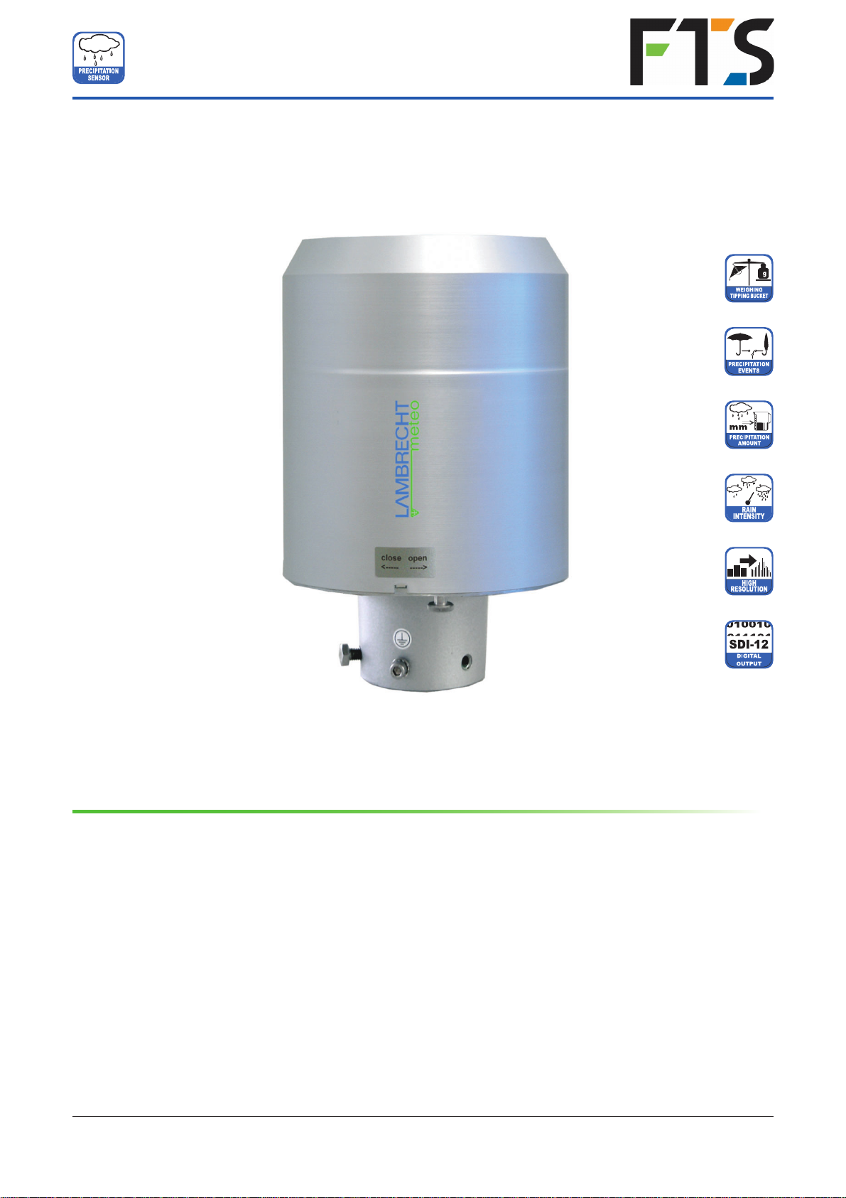
•SDI-RAINE-HYDRO sensor
•Collecting vessel
•Operating instructions
•USB-to-mini-USB cable
•Software rain[e]-Commander (download from the FTS Support website (https://support.ftsinc.com)
>Product Documentation>Sensors> SDI-RAINE-HYDRO> Resources. )
Check the delivery for transport damage. Document any damage and contact FTS Customer Service at
1-800-548-4264.
2 Order Codes
SDI-RAINE-HYDRO
The order codes for accessories and spare parts can be found in chapter “Equipment and Spare Parts”.
3 Safety Instructions and Warranty
This system is designed according to the state-of-the-art accepted safety regulations. However, please note the
following rules:
1. Before putting into operation please read all respective manuals!
2. Please observe all internal and state-specific guidelines and/or rules for the prevention of accidents. If
necessary ask your responsible safety representative.
3. Use the system only as described in the manual.
4. Always have the manual at hand at the installation site.
5. Use the system within the specified operating condition. Eliminate influences, which might impair the safety.
6. Prevent the ingress of unwanted liquids into the devices.
7. Funnel heating and drain heating can be very hot if the heating is operated with the housing open. There is
a risk of being burnt! It is therefore recommended that the connector of the heating supply be disconnected
during cleaning and maintenance work.
8. The measuring edge of the upper part of the housing is quite sharp. There is a risk of cuts. It is therefore
recommended that the measuring edge not to be pressed on and/or that gloves are worn!
Please note the loss that unauthorised manipulation of the system shall result in the loss of warranty
and non-liability. Changes to system components require express written permission from FTS. These
activities must be performed by a qualifi ed technician.
The warranty does not cover:
1. Mechanical damage caused by external impacts (e. g. icefall, rockfall, vandalism).
2. Impacts or damage caused by over-voltage or electromagnetic fields which are beyond the standards and
specifications of the device.
3. Damage caused by improper handling, e. g. by using the wrong tools, incorrect installation, incorrect electrical
installation (incorrect polarity) etc.
4. Damage caused by using the device outside the specified operation conditions.
3
SDI-RAINE-HYDRO
USER MANUAL
700-SDI-RAINE-HYDRO Rev1 03 Mar 2021
Part# 21184

4 Dimensional Drawing and Product Drawing
Measuring edge
Protective covering
Fastening screw
Mounting pedestal
Pole/tube
Mounting screws
Connector heating power
Connector sensor
Fig. 1a
Fig. 1b
4
Dimensions in mm
(11'5")
(8.8")
SDI-RAINE-HYDRO
USER MANUAL
700-SDI-RAINE-HYDRO Rev1 03 Mar 2021
Part# 21184

5 Introduction
The SDI-RAINE-HYDRO sensor (referred to as the RAINE-HYDRO in this document) measures precipitation
amount and intensity. It combines the latest weighing technology with a self-emptying collecting vessel,
allowing higher resolution and precision with minimal total volume compared to common tipping bucket
sensors. Additionally, the RAINE-HYDRO is much smaller than common weighing sensors, since there is no
need for a collecting container.
The main sensor is ahighly precise load cell with overload protection. Its temperature co-efficient can be
determined using a temperature sensor in the interior space if necessary. The pulses from the reed contact
generated by tipping the collecting vessel are used for error correction during periods of high intensity
precipitation. Furthermore, the self-emptying system allows weighing without interruption.
The RAINE-HYDRO calculates the following values:
►Amount of precipitation (Pulse)
The RAINE-HYDRO gives the amount of precipitation in real time via the pulse or analogue output with a
maximum resolution of 0.01 mm.
►Intensity within the last minute (SDI-12)
The RAINE-HYDRO measures 6 times per minute and sums these values up in a moving sum. That is,
every time a new value is measured, it is summed to the previous 5 values and thus generates the new
value for the intensity within the last minute.
Fig. 2
USB socket
5
SDI-RAINE-HYDRO
USER MANUAL
700-SDI-RAINE-HYDRO Rev1 03 Mar 2021
Part# 21184

►Intensity since last retrieval (SDI-12)
The difference in the amount of precipitation since the last retrieval is divided by the time since the last
retrieval. If the time is smaller than 30 s, the RAINE-HYDRO will use the “intensity within the last minute”
value.
►Amount since last retrieval (SDI-12)
The difference in the amount of precipitation between the current and the last retrieval.
►Minimum intensity within the last x minutes (SDI-12)
Every minute the value of the intensity within the last minute is compared to the current minimum value. If
the new value is smaller, it replaces the former minimum value.
►Maximum intensity within the last x minutes (SDI-12)
Every minute the value of the intensity within the last minute is compared to the current maximum value. If
the new value is bigger, it replaces the former maximum value.
►Average intensity within the last x minutes (SDI-12)
Counts the amount of precipitation in steps of 0.01 mm for x minutes and divides the result by x minutes.
►Variance (SDI-12)
Variance of measured values over 4 s
The two pulse outputs can be configured to return the amount of precipitation with resolutions between
0.01 and 1 mm and closing times between 10 and 500 ms.
6 Installation
6.1 Site Selection
To minimise the entry of splash water it is recommended that sites with hard ground like concrete are avoided.
Place the precipitation sensor on grass or other soft ground instead. In general the sensor should not be placed
on slopes or roofs. We recommend installation of the precipitation sensor at a distance of at least 2 m from any
obstacle or the obstacle height (above the gauge's orifice), and preferably at a distance of four times the
obstacle height. Vegetation around the site hasto be clipped regularly to the height of the sensor to prevent it
from disturbing the measurement and at the same time reduce wind influence.
6
SDI-RAINE-HYDRO
USER MANUAL
700-SDI-RAINE-HYDRO Rev1 03 Mar 2021
Part# 21184

6.2 Mounting
Necessary tools
►Wrench (13 mm)
►Allen key (6 mm)
►Slotted screwdriver (approx. 2.5 blade width)
• Unpack the device.
•Take the box of the collecting vessel out of the funnel of the RAINE-HYDRO.
•Check the collecting vessel for transport damage and put it back into its box for later installation.
•Place the sensor on a tube or pole with
an outer diameter of 60 mm. Ametallic
extension tube with a minimum length of
100 mm is recommended if a wooden pole
is used. Use a wrench (13 mm) to tighten
the screws in the mounting pedestal evenly.
Do not damage the measuring
edge.
•To improve the operating security in
lightning-prone areas it is suggested that the
sensor should be earthed via the integrated
earthing screw of the RAINE-HYDRO. The
illustration shows the steps of installation of
an earthing connection with a cable clip
and earthing screws onto the sensor. The
other end of the cable should be connected
to a ground nail.
Fig. 3
7
SDI-RAINE-HYDRO
USER MANUAL
700-SDI-RAINE-HYDRO Rev1 03 Mar 2021
Part# 21184

6.3 Integrated Collecting System
Fig. 4
Fig. 5
Inner protection cylinder
Illustrations using the example rain[e]
• Open the device.
◦Unscrew the knurled screw at the bottom.
◦Take hold of the casing and base and turn
the casing
in the “open” direction (anti-
clockwise).
◦Lift the casing with caution. Mind the
heater’s terminal plug.
The measuring edge of the upper
part of the housing is quite sharp.
There is a risk of cuts. It is therefore
recommended that the measuring
edge not be pressed on and/or that
gloves are worn!
• Place the housing aside.
• Lift inner protection cylinder.
8
SDI-RAINE-HYDRO
USER MANUAL
700-SDI-RAINE-HYDRO Rev1 03 Mar 2021
Part# 21184

• Unpack the collecting vessel.
• Insert the collecting vessel.
◦Insert collecting vessel against the
bearing spring with the site of the
magnet facing towards the reed contact
(Fig. 7)
◦Insert the other axis into the other
bearing.
◦Test for flawless tipping.
Fig. 6
Inner workings of the RAINE-HYDRO without
collecting vessel.
Fig. 7
9
SDI-RAINE-HYDRO
USER MANUAL
700-SDI-RAINE-HYDRO Rev1 03 Mar 2021
Part# 21184

Level the device with the assistance of the spirit
level (Fig. 8) by tightening the hexagon head
screws in the base evenly.
Fig. 8
Fig. 9
Fig. 10
• Reassembly
◦Carefully replace the inner protection
cylinder
.
◦
Plug in the heating terminal plug.
◦
Put the casing onto the device –aligning
the embossings with the notches (Fig. 9).
◦
Press down on the housing and turn it
clockwise towards “close”.
◦
Fasten the knurled screw.
◦
Insert the enclosed dirt trap spiral into the
funnel (Fig. 10).
The measuring edge of the upper
part of the housing is quite sharp.
There is a risk of cuts. It is therefore
recommended that on the measuring
edge not be pressed on and/or that
gloves are worn!
• Inserting the dirt trap spiral
Insert the enclosed dirt trap spiral in the fun-
nel. The spiral should be held in such a way
that a complete turn in the anti-clockwise
direction is possible. Push the dirt trap spiral
in circular motion from above into the funnel
opening.
• Removing the dirt trap spiral
Grab the dirt trap spiral in such a way that a
complete turn in the anti-clockwise direction
is possible and pull it in a circular motion
towards the funnel opening.
Einsetzen Entfernen
Insert Remove
In order to protect the collecting vessel
the dirt trap spiral must be inserted into
the collecting funnel.
10
SDI-RAINE-HYDRO
USER MANUAL
700-SDI-RAINE-HYDRO Rev1 03 Mar 2021
Part# 21184

6.4 Power and Signal Connection
To connect the RAINE-HYDRO to a data acquisition system an M12 connecting cable is required. Connect
the cable according to the connecting diagram.
Connecting cable sensor with flying leads 10m (42.8ft) FTS Part # RAINE-CBL-10M
The maximum distance between the RAINE-HYDRO and the data acquisition system depends on the
interfaces being used. The value for SDI-12 is obtained from the respective definitions of these standards.
• SDI-12
• Pulse output
70 m (229'8") unshielded, low voltage
cabling 1000 m (3280'10")
6.5 System Start
The system starts automatically after connecting all plugs. After ~15 s the system starts collecting data and sends
them to the attached data logger according to the device configuration. T
Overview status LED (green) on main board:
System start Permanent lighting of the LED for approx. 3 seconds
In operation Fast flashing of the LED
6.6 Available Outputs
The RAINE-HYDRO provides the following outputs:
Pulse Output:
• 1 galvanically isolated open-collector and
• 1 non-isolated open-collector selectable as
• Pulse Output
◦Resolution: 0.01...1 mm
◦Closing time: 10...500 ms (duty cycle of 1:1)
• Status Output (heating ON/OFF; rain YES / NO)
Serial output:
• SDI-12
6.7 Factory Settings
The factory settings of the RAINE-HYDRO according to the standard connecting diagram are:
• Galvanically isolated output as pulse output
Resolution: 0.1 mm
Closing time: 300 ms
• SDI-12 protocol activated
11
•Non Isolated pulse output
Resolution: 0.1 mm
Closing Time: 300 ms
SDI-12 Address: 0
Averaging time: 10 min
SDI-RAINE-HYDRO
USER MANUAL
700-SDI-RAINE-HYDRO Rev1 03 Mar 2021
Part# 21184

6.8
T
Terminal Assignment
All unused wires must be connected to unused pins or insulated to avoid malfunctions.
7
Connecting Diagram
Connecting Diagram
12
SDI-RAINE-HYDRO
USER MANUAL
700-SDI-RAINE-HYDRO Rev1 03 Mar 2021
Part# 21184

8 Configuration Software - rain[e] Commander
The RAINE-HYDRO is configured using rain[e] Commander found
on the FTS Support website (https://support.ftsinc.com/) >Product
Documentation>Sensors> SDI-RAINE-HYDRO> Resources. This
tool is used to configure the output signals of the RAINE-HYDRO.
Furthermore the load cell can be adjusted with the help of a reference
weight. The software also has an update function for the RAINE-
HYDRO firmware and a diagnosis function to control the
readiness for use of the RAINE-HYDRO.
To configure the RAINE-HYDRO, it has to be connected via the
USB service interface in the device interior to a PC with rain[e]
Commander installed.
It is recommended that the power plug and the sensor
connector are unplugged before opening the
RAINE-HYDRO case to prevent it from
mis-measuring. In addition, please use the
‘service function’, if your data logger has one.
RAINE-HYDRO Setup
When entering the Setup area, the user must first select the COM port to which the RAINE-HYDRO is
connected (from the drop-down menu) and retrieve the settings from the rain[e] (gear wheel icon)
After retrieving the data from the RAINE-HYDRO the setup screen shows the product ID, serial number,
hardware revision and firmware version of the device. In the ‘Quick Configuration’ section the program provides
buttons for the most common combination to configure the RAINE-HYDRO with a few clicks. The ‘Expert
Configuration’ section allows users to customise the output signals in any desired way.
Fig. 13
Fig. 12
Lambrecht.net
Setup
Adjust rain[e]
load cell
Diagnostics
Upload firmware
to rain[e]
Exit program
13
Quick Configuration
To configure the RAINE-HYDRO
with the Quick Configuration screen
click on the buttons representing
the desired options and sub-
options. After each selection the
changes will be sent to the RAINE-
HYDRO. The output field shows the
current settings and it will be
updated automatically after sending
new settings to the RAINE-HYDRO.
SDI-RAINE-HYDRO
USER MANUAL
700-SDI-RAINE-HYDRO Rev1 03 Mar 2021
Part# 21184

Pulse Output
SDI-12 OFF
RS485 ASCII ON
Pulse Output (isolated) ON
Operating Mode Pulse
Resolution 0.10 mm/m²
Closing Time 300 ms
Analogue Output OFF
Pulse Output (not isolated) ON
Operating Mode Heating ON / OFF
• Standard Resolution
Pulse Output (isolated) ON
Resolution 0.10 mm/m²
Closing Time 300 ms
• High Resolution
Pulse Output (isolated) ON
Resolution 0.01 mm/m²
Closing Time 10 ms
Expert Configuration
Fig. 14
14
SDI-RAINE-HYDRO
USER MANUAL
700-SDI-RAINE-HYDRO Rev1 03 Mar 2021
Part# 21184

The Expert Configuration screen is an easy to use tool to completely customise the configuration of the rain[e]
output signals. Options are visible depending on the selected output modes. The following list shows the available
options, sub-options and value ranges.
Pulse Output (non-isolated) / (isolated)
• Operating Mode
◦Pulse
►Closing Time 10...500 ms in steps of 5 ms
►Resolution 0.01...1 mm in steps of 0.01 mm
◦Rain YES / NO
Precipitation Event (non-isolated) / (isolated)
►Amount 0.10...1 mm in steps of 0.10 mm
►Start Time 20...60 s in steps of 1 s
►End Time 20...600 s in steps of 1 s
Serial Port
• Operating Mode
◦SDI-12
►Average Time 1...60 min in steps of 1 min
SDI-12 - Address 0...9, A...Z, a...z
Load Cell Adjustment
Fig. 15
The Load Cell Adjustment screen may be used to adjust the load cell. It will give the number of cycles the program
has carried out, the mean value of the measured weight and the variance of the values. If a calibration weight is
used, a calibration factor will be given.
To adjust the load cell first select the COM port of the RAINE-HYDRO from the drop-down menu. If desired, put
a calibration weight in the collecting vessel and enter the weight into the corresponding text box. To start the
adjustment click the green Start Adjustment button.
Pressing the button with the red ‘X’ will stop the running adjustment.
Adjustment has to done again if the deviations in the diagnostics are higher than ± 30 mg.
15
SDI-RAINE-HYDRO
USER MANUAL
700-SDI-RAINE-HYDRO Rev1 03 Mar 2021
Part# 21184

Firmware Update
Diagnostics
Fig. 17
The “Diagnostics” mask is divided into three tabs: “Status” - to check the system status, “Scale” - to test the load
cell and “Simulation” - to simulate precipitation amounts to check the output signals of the impulse and analogue
outputs.
To use any of these functions the COM port of the connected RAINE-HYDRO has to be selected from the
drop-down menu.
To check the system status one has to click “Retrieve rain[e] Status” (gear wheel icon) in the tab “Status”. The
program will return the following status message:
Heating Temperature - OK / Malfunction Not exceeding the heating temperature by 10 °C
Heating Test - OK / Malfunction Working Heating
Temperature Sensor Bottom - OK / Malfunction Working Temperature Sensor Bottom
Temperature Sensor Top - OK / Malfunction Working Temperature Sensor Top
Status 6-9 Internal use only
16
Firmware updates will be posted on the FTS Customer Support website (https://support.ftsinc.com/).
Firmware updates are published to enhance or improve sensor performance and should be applied when
released to ensure optimal sensor performance.
To update the firmware, use the firmware Update screen. Select the COM port of the connected RAINE-
HYDRO from the drop-down menu, click Browse for Firmware File 9folder icon) and select the firmware file
on your computer or tablet. Then click Load Firmware to rain[e] (syringe icon).
Fig. 16
SDI-RAINE-HYDRO
USER MANUAL
700-SDI-RAINE-HYDRO Rev1 03 Mar 2021
Part# 21184

To test the weighing scale one has to put a (known) weight into one pan of the collecting vessel and click “Test
Scale” (blue gear wheel icon) in the tab “Scale”.
To simulate precipitation amounts to check the output signals of the pulse and analogue outputs, one has to
select the desired amount from the drop-down menu in the tab “Simulation” and click “Simulate Precipitation”
(cloud icon). The analogue and pulse outputs will return signals according to the applied settings in the rain[e]
Setup.
9 SDI-12 Interface
The communication using SDI-12 protocol via SDI-12 interface is based on the ‘SDI-12 A Serial-Digital
Interface Standard for Microprocessor-Based Sensors, Version 1.3, 2012’. The RAINE-HYDRO can be used in
bus mode parallel to other RAINE-HYDROs.
The following subset of SDI-12 commands were implemented into the RAINE-HYDRO.
For further details to the SDI-12 protocol we recommend the afore-mentioned standard document or the website
www.SDI-12.org.
Implemented SDI-12 commands:
Command Function Answer of the sensor
a! Acknowledge Active a<CR><LF>
?! Address Query Command a<CR><LF>
aI!Send Identification allccccccccmmmmmmvvvxx...xx<CR><LF>
aAb! Change Address b<CR><LF>
aM! Start Measurement atttn<CR><LF>
aMC! Start Measurement and Request CRC atttn<CR><LF>
aC! Start Concurrent Measurement atttnn<CR><LF>
aCC! Start Concurrent Measurement and Request
CRC checksum
atttnn<CR><LF>
aD0!
aD1!
Send Data (Puffer 0)
Send Data (Puffer 1)
a<values<CR><LF>
a<values><CRC><CR><LF>
resp. with CRC checksum
aM1! Generate Variance atttn<CR><LF>
aM2! Generate Heating Data atttn<CR><LF>
aM3! Start Intensity Measurement Average Value,
Maximum and Minimum
atttn<CR><LF>
aMC1! Generate Variance and Request CRC atttn<CR><LF>
aMC2! Generate Heating Data and Request CRC atttn<CR><LF>
aMC3! Start Intensity Measurement Average Value,
Maximum and Minimum and Request CRC
atttn<CR><LF>
aC1! Generate Variance atttnn<CR><LF>
aC2! Generate Heating Data atttnn<CR><LF>
aC3! Start Intensity Measurement Average Value,
Maximum and Minimum
atttnn<CR><LF>
aCC1! Generate Variance and Request CRC atttnn<CR><LF>
aCC2! Generate Heating Data and Request CRC atttnn<CR><LF>
aCC3! Start Intensity Measurement Average Value,
Maximum and Minimum and Request CRC
atttnn<CR><LF>
aV! Start Verification atttn<CR><LF>
a = address of the respective sensor; standard sensor address = 0
17
SDI-RAINE-HYDRO
USER MANUAL
700-SDI-RAINE-HYDRO Rev1 03 Mar 2021
Part# 21184

SDI-12 commands always start with the address of the appropriate sensor. Therefore all other sensors on the
same bus will ignore these commands. SDI-12 commands end with ‘!’. All answers from sensors start with its
address, too, but end with the ASCII characters ‘Carriage Return’ <CR> and ‘Line Feed’ <LF>.
The SDI-12 protocol is based on the ASCII character set. The baud rate of the SDI-12 protocol is 1200 Bd and
has the byte frame format:
1 start bit
7 data bits (least significant bit transmitted first)
1 parity bit (even parity)
1 stop bit.
Acknowledge Active - a!
This command ensures that the sensor responds to requests from the master. Basically it asks the sensor to
confirm it is connected to the bus.
The sensor returns its address and <CR><LF>.
Syntax
Command Answer
a! a<CR><LF>
a– Sensor address a– Sensor address
!– End of command <CR><LF> – End of answer
Example:
Command Answer
0! 0<CR><LF>
1! 1<CR><LF>
Send Identification - aI!
The command aI!is used to ask the sensor for its model number and firmware version.
Syntax
Command Answer
aI! a 13LMGmbH1515184x1.0781129.0001<CR><LF>
a– Sensor address a– Sensor address
I– Command ‘Send Identification’
13LMGmbH1515184x1.0781129.0001
13 – 2 characters SDI-12 version-No.
13 = version 1.3
LMGmbH15 – 8 characters manufacturer’s
name (= Lambrecht meteo
GmbH)
15184x – 6 characters sensor type
(= precipitation sensor rain[e])
1.0 – Sensor version (= version 1)
781129.0001 – 11 characters serial No.
!– End of command <CR><LF> – End of answer
Example:
Command Answer
0I! 013LMGmbH1515184x1.0781129.0001<CR><LF>
1I! 113LMGmbH1515184x1.0781129.0002<CR><LF>
18
SDI-RAINE-HYDRO
USER MANUAL
700-SDI-RAINE-HYDRO Rev1 03 Mar 2021
Part# 21184

Change Address - aAb!
The factory setting of the address is ‘0’. If there are several sensors connected to one bus, the sensor address
can be changed with the command aAb!. The address is always a single ASCII character. Standard for addresses
are the ASCII characters ‘0’ to ‘9’ (decimal 48 to 57). If there are more than 10 sensors connected to one bus,
using the characters ‘A’ to ‘Z’ (decimal 65 to 90) and ‘a’ to ‘z’ (decimal 97 to 122) is allowed. The sensor answers
with its new address and <CR><LF>. After the address is changed, one should not send further commands to
the sensor for a period of one second (see also ‘SDI-12 Standard, Version 1.3, 2012’).
Syntax
Command Answer
aAb! b<CR><LF>
a– Old sensor address b– New sensor address
A– Command ‘Change Address’
b– New sensor address
!– End of command <CR><LF> – End of answer
Example:
Command Answer
0A1! 1<CR><LF>
Start Measurement - aM!
The command aM! requests that the sensor process the returning string and provide the available measured data.
In contrast to standard sensors described in the SDI-12 documentation the RAINE-HYDRO measures continuously.
Thus the measured values from the continuous measurement are stored in a buffer while the string is being
processed. These values are processed after the string processing.
Therefore the RAINE-HYDRO always responds with ‘a003x’. This is also the reason why the RAINE-HYDRO does
not send a Service Request and ignores signals to interrupt the measurement. Prior to the returned waiting time (3 s)
the data logger must not send further commands. After expiration of the waiting time the data can be requested with
the commands aD0! and aD1! (see Send Data). The data will not be overwritten until the next C, M, or Vcommand
and can be read several times until then.
Syntax
Command Answer
aM! a0036<CR><LF>
a– Sensor address a– Sensor address
M– Command ‘Start Measurement’ 003 – Seconds the sensor needs until the
measured data can be returned
(=3s)
06 – Number of provided measured data
!– End of command <CR><LF> – End of answer
Example:
Command Answer
1M! 10036<CR><LF>
The measured data can be requested with the commands aD0! and aD1!. (see Send Data).
19
SDI-RAINE-HYDRO
USER MANUAL
700-SDI-RAINE-HYDRO Rev1 03 Mar 2021
Part# 21184

Start Measurement and Request CRC - aMC!
Same command as aM! but in addition to the generated data the sensor returns a 3-digit CRC checksum. For
information on how the CRC checksum is generated, please consult ‘SDI-12 Standard, Version1.3, 2012, chapter
4.4.12’.
Syntax
Command Answer
aMC! a0036<CR><LF>
a– Sensor address a– Sensor address
M– Command ‘Start Measurement 003 – Seconds the sensor needs until the
and Request CRC’ measured data can be returned
C– Request for transmission of the (= 3 s)
CRC checksum 6– Number of provided measured data
!– End of command <CR><LF> – end of answer
Example:
Command Answer
2MC! 20036<CR><LF>
Start Concurrent Measurement - aC!
The Concurrent Measurement enables the data logger to measure simultaneously with multiple rain[e]s on the
same bus.
The command aC! requests that the sensor process the returned string and to provide the available measured
data.
In contrast to standard sensors described in the SDI-12 documentation, the RAINE-HYDRO measures
continuously. Thus the values during continuous measuring are stored in bu fferwhilethestringisbeing
processed. These values are processed after the string processing. Prior to the return waiting time (3 s) the
data logger must not send further commands. After expiration of the waiting time the data can be requested
with the commands aD0! and aD1! (see Send Data).
The data will not be overwritten until the next C, M, or Vcommand and can be read several times in the mean
time.
Syntax
Command Answer
aC! a00306<CR><LF>
a– Sensor address a– Sensor address
C– Command ‘Start Concurrent 003 – Seconds the sensor needs until the
Measurement’measured data can be returned
(=3s)
6– Number of provided measured data
!– End of command <CR><LF> – End of answer
Example:
Command Answer
2C! 200306<CR><LF>
The measured data can be requested with the commands aD0! and aD1!. (see Send Data).
20
SDI-RAINE-HYDRO
USER MANUAL
700-SDI-RAINE-HYDRO Rev1 03 Mar 2021
Part# 21184
Table of contents
Other FTS Accessories manuals
Popular Accessories manuals by other brands

Barksdale
Barksdale BPT1000 installation instructions

Barton
Barton 96074 Owner's manual and safety instructions

RTS
RTS BTR-240 user manual

Dometic
Dometic OASIS ELITE 975 Series Installation & operation manual

UPPAbaby
UPPAbaby RUMBLESEAT V2 manual

Siko
Siko MSA510 Translation of the original installation instructions