Noraxon Ultium Motion User manual
Ultium Motion Quick Start Guide
1
(Rev A)
Ultium™ Motion
Quick Start Guide

Ultium Motion Quick Start Guide
2
(Rev A)
On behalf of Noraxon…
Welcome and congratulations on acquiring your new Ultium Motion System!
This guide will provide you with step-by-step instructions on how to install your new hardware and software, adjust device
settings, and record your first data set.
Let us begin by walking through how to install your new hardware.
Note: This is not meant to be a complete user manual, but a guide to help you get started with your system. For more
detailed operating instructions for the Ultium Motion System, please refer to the Ultium Motion User Manual (P-8708).
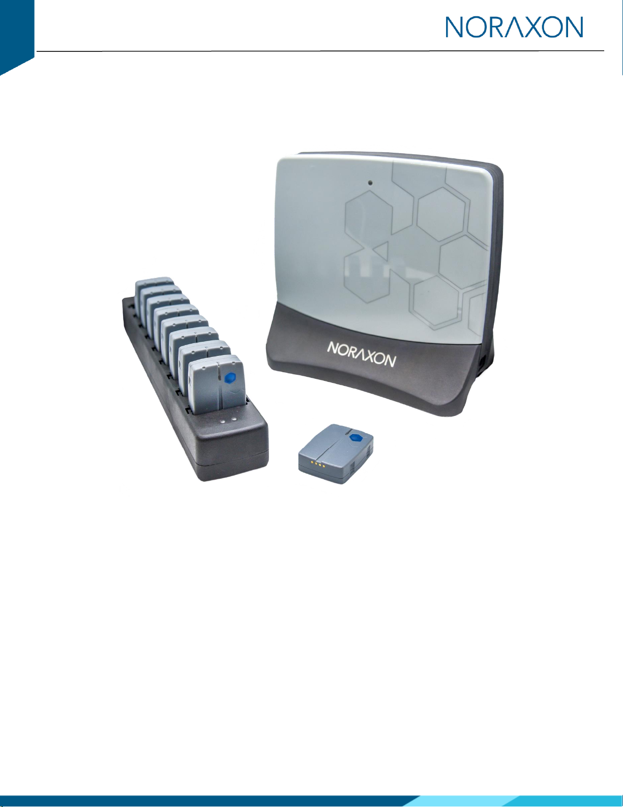
1System Unboxing
The Ultium Motion System is packed within a reinforced padded box for storage and protection during transport. Upon
arrival, carefully remove all contents and verify the following components are present.
Figure 1 –Ultium Receiver (#880)
Figure 2 –Ultium Sensor Charger (#873)
Figure 3 –Motion Sensor
(#870 or #876)
Figure 4 –Sensor Charger to Receiver Cable
(#CBL34)
Figure 5 –A to B USB Cable (#CBL2)
Figure 6 –Sensor Charger Power
Source (#PSU1)
Additional items that may be included with your Ultium Motion System are:
•Ultium Motion Strap Set (#874X, #874Y, or #874Z)
•Double-Sided Sensor & Torso Adapter Tape (#874D & #874E)
•Sensor Body Segment Label Set (#610A)
•Ultium Motion User Manual (#P-870)
2Installing the Hardware
Step 1

Ultium Motion Quick Start Guide
3
(Rev A)
Insert the USB cable (CBL2) into the USB connector on the
back of the Ultium Receiver (880).
Insert the opposite end of the USB cable into an available
USB port on the computer.
Step 2
Insert the Motion Sensors (870) into the Sensor Charger
(873).
Note: Sensor power button & LED must face the front of
the Charger, i.e., toward the charger LEDs.
Step 3
Connect the Receiver to the Sensor Charger (873) using
the ports on either side of the Receiver.
Step 4
Insert the power supply (PSU1) barrel connector into the
associated receptacle on the back of the Ultium Receiver
to charge sensors.
Note: Sensor LED will show solid orange while charging
and turn off when fully charged.
Ultium Motion Quick Start Guide
4
(Rev A)
3Installing the Companion Software - myoRESEARCH™ 3
To utilize the full functionality of the Ultium Motion system, and ensure the system has updated drivers, Noraxon’s
myoRESEARCH 3 (MR3) needs to be installed on the computer.
Note: The Ultium Receiver requires the Noraxon USB device driver which is pre-installed by the MR3 software installation. It
is also available in the Downloads section of the Noraxon website.
3.1 Software Installation
Within the Ultium Motion System shipment, there is a USB flash drive containing the latest myoRESEARCH 3 software.
1. Insert the MR3 USB flash drive into the PC
2. Open the installer application (e.g., noraxon.mr.3.18.00) and follow the instructions
3. After installation, an icon will be created on the desktop
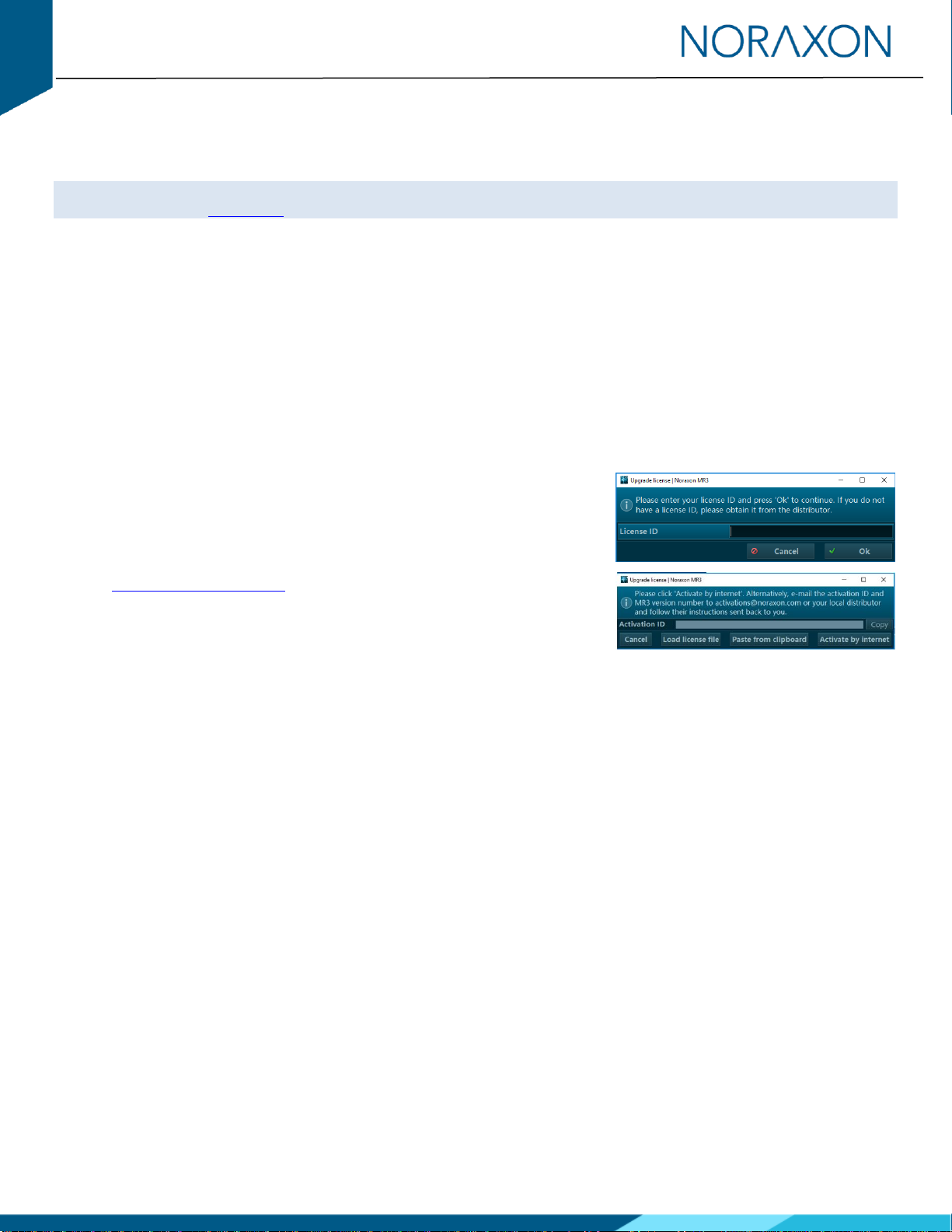
3.2 Companion Software Activation
The companion software must be activated before unrestricted use is possible.
1. Open MR3
2. A dialog box will indicate how many more times MR3 can be opened
3. Click “Activate”
4. Enter the License ID provided on your USB flash drive and press “OK”
5. If you have an internet connection, click Activate by Internet for
immediate activation.
6. Alternatively, email the provided activation ID to
activatio[email protected].
7. Noraxon Support will email or respond by phone with the Activation
Code.
8. Enter the provided Activation Code to remove any restrictions on use.

Ultium Motion Quick Start Guide
5
(Rev A)
4Configuring the Hardware
Before the Ultium Motion system can be used, the device software settings must be configured to recognize the different
components that make up the system. Follow the instructions below to update the receiver firmware, sensor firmware, and
sensor assignment to prepare for a data collection.
Step 1
Open the MR3 software and click on the Hardware Setup
button in the upper right-hand corner.
Step 2
After connecting the Ultium Receiver to the USB port on
the computer, select the Ultium icon, within the ‘New
Devices’area, and click the Insert button.
Step 3
The Ultium hardware setup window will appear as
shown.
Within the “General” tab, select the desired settings for
the system, i.e., name, sample rate.
Note: If available, firmware updates for the Receiver and
Sensors will be indicated here.
If using myoSYNC, click the Use Noraxon myoSYNC
checkbox.
Additional settings are available within the “Advanced”
tab.
Note: If multiple Ultium systems are in use, separate
networks assignments are required for each Receiver.

Ultium Motion Quick Start Guide
6
(Rev A)
Step 4
Make sure the Motion Sensors are placed in the
Charger(s) and the Charger(s) are connected to the
Ultium Receiver, then click Detect Sensors in Chargers to
load all sensor serial numbers into the MR3 software.
Note: The first serial number in the list is associated with
the Sensor closest to the front of the Charger (i.e., toward
the Charger LEDs).
Step 5
After detection is complete, click Replace to replace all
existing sensor serial numbers associated with this
device or Add to append additional sensor serial numbers
to an already existing list.
Step 6
Assign sensors to body segments by clicking the
dropdown and selecting the desired location from the
pop-up menu.
Note: Segments already assigned to a sensor will display
a green dot next to the segment name.
Step 7
Click OK (in the bottom right corner of the dialog box) to
save the hardware settings.

Ultium Motion Quick Start Guide
7
(Rev A)
5Attaching the Sensors
Before performing a recording, decide which body segments will be included in the recording. The sensors can be attached
with the provided fixation straps. For high velocity and heavy impact movements, we recommend additional fixation of the
sensors with the use of elastic self-adhesive tape.
Note: Best practices for sensor placement and fixation are explained further in the Ultium Motion User Manual (P-8708).
5.1 Sensor Placement Locations
Head
Middle of the back of the head
Upper
Thoracic
In line with the spinal column at C7/T1, but high
enough to not be affected by upper trapezius muscle
movement.
Lower
Thoracic
In line with the spinal column at L1/T12.
Pelvic
Body area of sacrum
Upper
Arm
Midway between the shoulder and elbow joints,
lateral to the bone axis
Forearm
Posterior distal region, where there is a low amount
of muscle tissue
Hand
Dorsum of the hand
Thigh
Anterior distal half of the femur body, where there is
a lower amount of muscle displacement during
motion
Shank
Slightly medial to the anterior border of the tibia
Foot
Dorsal midfoot region
Figure 7: Lower body sensor placement
Figure 8: Upper body sensor placement
Ultium Motion Quick Start Guide
8
(Rev A)
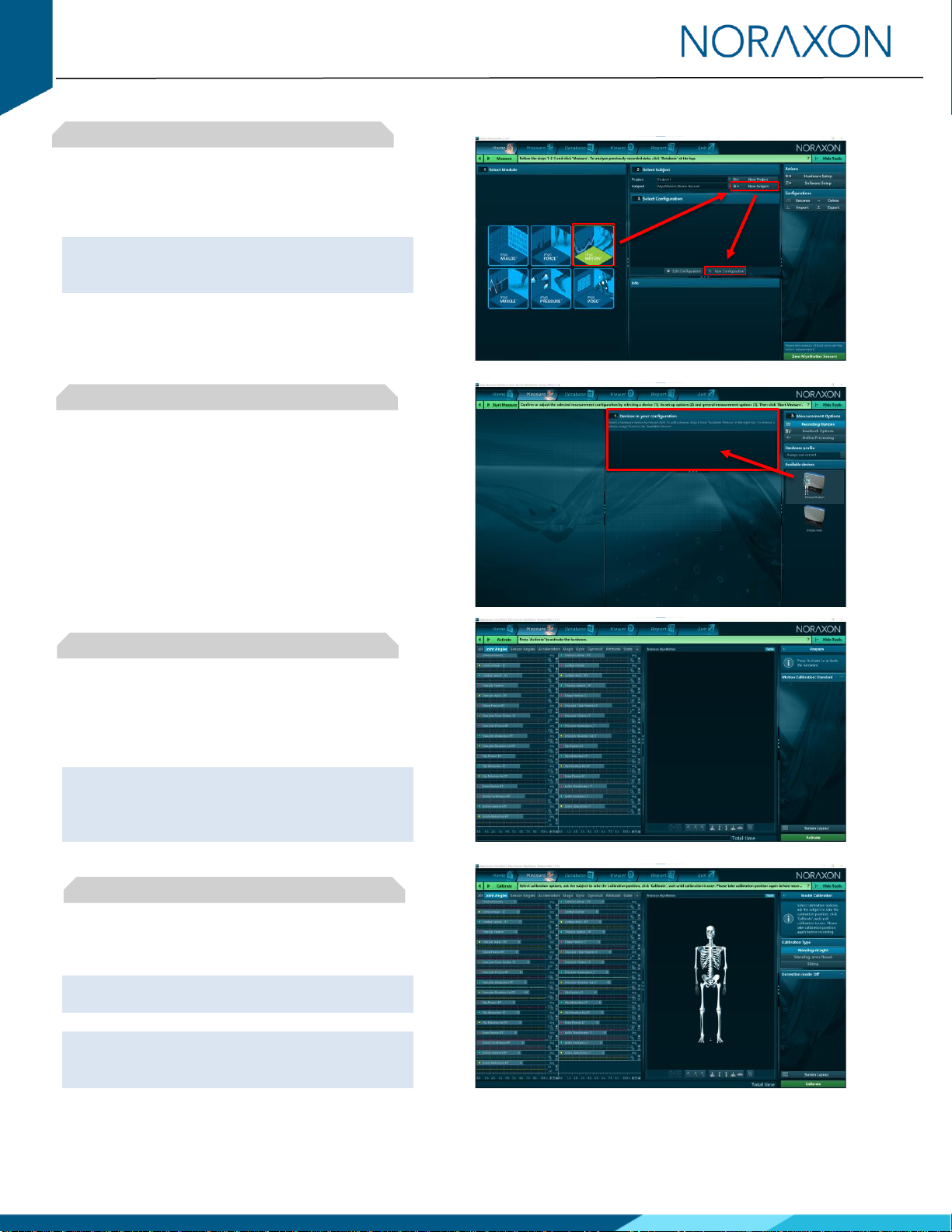
6Recording a Measurement
Step 1
On the Home screen, click the myoMOTION
module icon.
Create a New Subject.
Note: Defining the subject’s height is required to
compute bone lengths and create an accurate
skeletal avatar.
Select New Configuration.
Step 2
Insert the Ultium Motion device into the
configuration by dragging it from the list of
Available Devices to the Devices in Your
Configuration area.
Select the desired body segment sensors and
associated data to include in the measurement
configuration.
Step 3
Continue to the next step by clicking Start
Measure.
Activate the hardware by clicking Activate.
Note: If operating within a distorted magnetic
environment, open the Motion Calibration
dropdown menu on the right-side toolbar to select
a Functional Calibration, then click Activate.
Step 4
In the right-side toolbar, select the desired
calibration method.
Note: If desired, select a Correction Mode from the
right-side toolbar prior to calibrating.
Note: If using a Functional Calibration, follow the
instructions from the software wizard in the right-
side toolbar.

Ultium Motion Quick Start Guide
9
(Rev A)
Step 5
Ensure the subject is in the calibration position and
prepared to hold this position for 8 seconds during
the calibration procedure.
Click Calibrate to proceed and monitor the subject
to confirm the calibration position was held for the
entire calibration process.
Step 6
After performing the calibration, click Record to
begin recording data.
When you are ready to end the recording, click
Stop.
Save the recording to the database and type in a
desired name, then click Discard & Measure Again
or Save & Measure Again to return to the
measurement screen or click Save & View to
visualize the recording.
7Viewing a Record
To view a previously recorded record, click the Database tab. Records are organized by Project and Subject name. Double-
click on the record of interest to open the record in the Viewer tab.
8Further Use Features of MR3
There are many additional features built within MR3. Such as:
•Multi-activity recordings
•Live biofeedback visual displays
•Online and post-measurement signal processing
•Customized reporting
•Exporting (and importing) of data
To learn more about the features available to you through the system(s) you have purchased, refer to the myoRESEARCH
User Manual and the corresponding Hardware User Manual for this device (P-8708).
Other manuals for Ultium Motion
2
Table of contents
Other Noraxon Accessories manuals


