Noraxon Ultium Linear Force SmartLead User manual
Linear Force SmartLead
P-802 Rev B (May 2019)
i
Ultium™Biomechanics
Research System
Ultium Linear ForceSmartLead
User Manual
Linear Force SmartLead
P-802 Rev B (May 2019)
ii
For questions, concerns or additional assistance please contact Noraxon or its
Authorized Representative as specified below.
M - Manufacturer:
Noraxon U.S.A. Inc.
15770 North Greenway-Hayden Loop, Suite 100
Scottsdale, AZ 85260
Tel: (480) 443-3413
Fax: (480) 443-4327
Email: [email protected]
Web Site: www.noraxon.com
P- Authorized European Representative:
EC
REP
Advena Limited, Tower Business Centre, 2nd Flr., Tower Street, Swatar,
BKR 4013 Malta
Website: http://www.advenamedical.com
No part of this document may be copied, photographed, reproduced, translated, or reduced to
any electronic medium or machine-readable form without prior written consent of Noraxon U.S.A.
Inc.
Noraxon and myoRESEARCH are registered trademarks and the Noraxon logo, myoANALOG, myoFORCE, myoMETRICS, myoMOTION,
myoMUSCLE, myoPRESSURE, myoVIDEO, myoSYNC, NiNOX, TRUsync and Ultium are common-law trademarks of Noraxon U.S.A., Inc.
All other trademarks are the property of their respective owners. ©2018, all rights reserved.
CE Mark: This symbol indicates the clearance to
market this product in the European Community.

Linear Force SmartLead
P-802 Rev B (May 2019)
iii
Table of Contents
1 Introduction................................................................................................................................... 1
1.1 Brief Description..................................................................................................................... 1
1.2 Contraindications ................................................................................................................... 1
2 Definitions..................................................................................................................................... 1
2.1 Graphic Symbols and Meaning.............................................................................................. 1
2.2 Glossary of Terms.................................................................................................................. 2
3 Identification.................................................................................................................................. 3
3.1 Model Designation ................................................................................................................. 3
3.2 Product Versions and Configurations .................................................................................... 3
4 General Warnings and Cautions .................................................................................................. 4
4.1 Risks and Benefits ................................................................................................................. 4
4.2 Safety Information Summary ................................................................................................. 4
5 Getting Started.............................................................................................................................. 5
5.1 Quick Start Guides................................................................................................................. 5
6 Preparing the Product for Use...................................................................................................... 6
6.1 Unpacking and Component Identification.............................................................................. 6
6.2 Component Inputs, Outputs and Indicators ........................................................................... 6
6.3 Component Interconnections................................................................................................. 7
6.4 Device Communication (Driver) Software Installation ........................................................... 8
6.5 Companion Software Installation........................................................................................... 9
6.5.1 MR3 Installation............................................................................................................... 9
6.6 Companion Software Configuration....................................................................................... 9
6.6.1 MR3 Configuration ........................................................................................................ 10
6.6.2 Find My Sensor Feature................................................................................................ 12
7 Pre-Use Check-Out .................................................................................................................... 13
7.1 Normal Appearance of Signals............................................................................................ 13
8 Operating Instructions ................................................................................................................ 14
8.1 Safety Information Summary ............................................................................................... 14
8.2 Normal Functions with Interface to a PC ............................................................................. 14
8.3 Exceptional Functions/Situations (error messages) ............................................................ 14
8.4 Shutdown after Use ............................................................................................................. 14
8.5 Storage and Protecting Between Usages............................................................................ 14
9 Accessories and Optional Modules............................................................................................ 15
9.1 Accessories.......................................................................................................................... 15

Linear Force SmartLead
P-802 Rev B (May 2019)
iv
10 Cleaning.................................................................................................................................... 15
10.1 Safety Precautions When Cleaning................................................................................... 15
11 Maintenance............................................................................................................................. 16
11.1 Device Software (firmware) updates.................................................................................. 16
11.2 Maintenance by Qualified Individuals ................................................................................ 16
11.3 Companion Software Updates........................................................................................... 16
12 Trouble Shooting, Fault Diagnosis ........................................................................................... 17
Website Link to FAQ.................................................................................................................. 17
13 Service and Repair................................................................................................................... 17
13.1 Availability of Circuit Diagrams and Component Lists....................................................... 17
13.2 Warranty Information ......................................................................................................... 17
13.3 Submitting Technical Support Requests............................................................................ 18
13.4 Returning Equipment......................................................................................................... 18
14 Spare Parts and Consumables................................................................................................. 18
Consumable Items..................................................................................................................... 18
Replaceable Items ..................................................................................................................... 18
15 Specifications of the Product.................................................................................................... 19
15.1 Expected Useful Lifetime................................................................................................... 19
15.2 Technical Specifications .................................................................................................... 19
Environmental Conditions for Storage and Transport................................................................ 19
16 Technical Information ............................................................................................................... 19
Part 820/821 Linear Force (Ultium Linear Force SmartLead SmartLead)............................. 19

Linear Force SmartLead
P-802 Rev B (May 2019)
1
1 Introduction
1.1 Brief Description
The Linear Force SmartLead is an accessory to the Ultium EMG sensor (#810) which allows a user
to determine the magnitude of force executed about a single axis over time. One could use this tool
for a variety of use cases such as measuring and comparing an individual’s pull strength between
arms.
1.2 Contraindications
Use of the Ultium system is contra-indicated in individuals who have implanted pacemakers.
2 Definitions
2.1 Graphic Symbols and Meaning
The following international icons and symbols may be found on the Ultium Linear Force SmartLead
enclosures and in this user manual. Their meaning is described below.
Read material in the Instruction Manual wherever this symbol
appears.

Linear Force SmartLead
P-802 Rev B (May 2019)
2
2.2 Glossary of Terms
Ultium Sensor -- A small individual radio transmitter typically worn on the body used to measure
and transmit bio-potential signals (such as EMG) or motion related signals (such as acceleration).
The Ultium Systems can accommodate up to 16 body worn Ultium Sensors in one network. Two
Ultium Systems may be used in parallel, on separate RF networks, to accommodate up to 32 body
worn sensors.
Ultium SmartLead –Refers to different data collection modalities. Each SmartLead measures a
given type of physical parameter. Different SmartLeads can be combined in the same Ultium
network. The most common Ultium SmartLead is EMG. Examples of other types include
Accelerometers, Goniometers and Force sensors.
Ultium Serial Number –A unique five-character tag used to identify each Ultium Sensor or Ultium
Smartlead. The members of any Ultium network are determined by their serial numbers. Also,
Ultium Sensor Types are grouped into a predefined range of serial numbers. Thus, by serial number
the Ultium system can automatically determine the type of signal parameter being transmitted
from any Ultium Sensor or Ultium SmartLead in the network.
Multi-Channel Sensor –Certain Ultium Sensor Types provide more than one signal. An example is
a 3-D Accelerometer that provides acceleration data for the x, y and z directions.

Linear Force SmartLead
P-802 Rev B (May 2019)
3
3 Identification
3.1 Model Designation
Ultium Linear Force SmartLead, 500 lbF (Part #820) or 100 lbF (Part #821)
3.2 Product Versions and Configurations
The model 820/821 Ultium Linear Force SmartLead must be utilized in conjunction with the Ultium
EMG Sensor (Part# 810) and the Ultium Receiver (Part #880).
For additional equipment details refer to Section 9 of this manual.
As the Noraxon Systems require software to perform its function, the equipment is offered in
combination with the following computer program packages:
Model #402 MR3 myoMuscle Module

Linear Force SmartLead
P-802 Rev B (May 2019)
4
4 General Warnings and Cautions
4.1 Risks and Benefits
There is no identified risk of physical harm or injury with use of the Ultium Linear Force
SmartLead. The benefit provided by use of the device is the provision of objective measures to
assess the severity of pathological human movement conditions and gauge any subsequent
improvement offered by therapy, training, prosthetic alterations or ergonomic design changes.
4.2 Safety Information Summary
Cautions
•Never use the Ultium Linear Force SmartLead to collect data from a person with an
implanted pacemaker
•Never operate the Ultium Linear Force SmartLead within 1 meter of any critical medical
device
Warnings
•Do not immerse the Ultium sensors in any water or liquid
•Do not use the Ultium equipment on individuals undergoing MRI, Electro Surgery or
Defibrillation
•The Ultium Linear Force SmartLead produces results that are informative, not diagnostic.
Qualified individuals must interpret the results
Attention
•The operator must be familiar with typical characteristics of the signals acquired by the
Ultium Linear Force SmartLead and be able to detect anomalies that could interfere with
proper interpretation.

Linear Force SmartLead
P-802 Rev B (May 2019)
5
5 Getting Started
5.1 Quick Start Guides
Please see the hardware manual for the appropriate EMG system.
P-880: Ultium user manual

Linear Force SmartLead
P-802 Rev B (May 2019)
6
6 Preparing the Product for Use
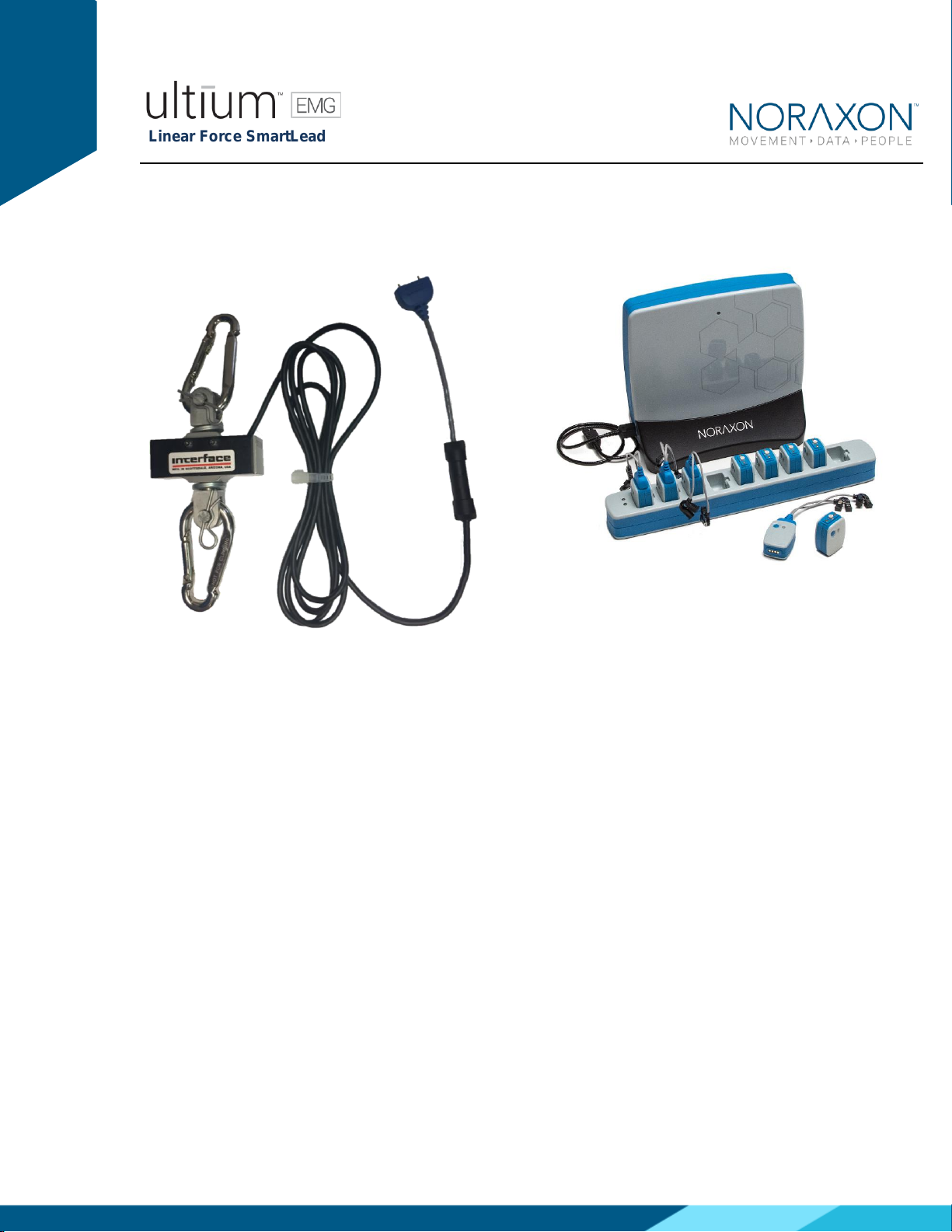
6.1 Unpacking and Component Identification
Ultium Linear Force SmartLead (Part
#820 or 821)
Ultium Linear Force SmartLead with
SML Load Cell (Part #SML-500 or
#SML-100)
Additional contents not illustrated
Ultium Linear Force SmartLead User Manual (part #820/821A) This document
If additional accessories have been included please see Section 9, Accessories for component
identification.
6.2 Component Inputs, Outputs and Indicators
1) EMG Sensor (front and top edge)
Smart Lead Connector –Connector for
smart leads to change function of EMG
sensor.

Linear Force SmartLead
P-802 Rev B (May 2019)
7
Status LED –Sensor operational indicator
flashes green when measuring. Solid
Yellow when charging.
Power Button –Power the sensor On/Off.
Hold for 3+ seconds for a hard reset.
2) EMG Sensor (back and bottom edge)
Charger Contacts –Sensor battery is
charged and sensor data is exchanged
through these points.
Serial Number –Unique 5-character serial
number which identifies each EMG sensor.
3 Linear Force SmartLead
Serial Number: Unique 5-character serial
number which identifies each SmartLead.
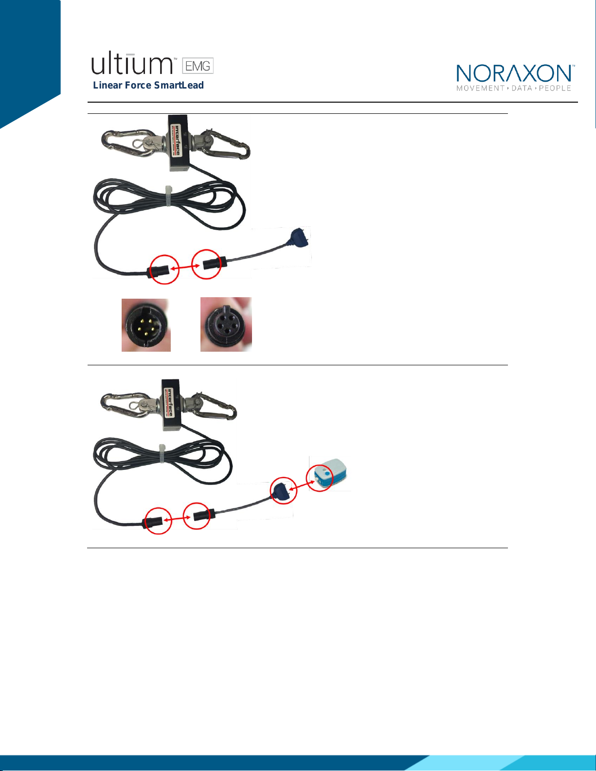
6.3 Component Interconnections
Step 1
Connect the Ultium Linear Force
connector (Male 5-pin
connector) with the Ultium Load
Cell connector (Female 5-pin
connector)
Linear Force SmartLead
P-802 Rev B (May 2019)
8
Step 2
Connect the Linear Force
SmartLead to the Ultium EMG
sensor.
6.4 Device Communication (Driver) Software Installation
No driver installation is needed. The Ultium Receiver communicates over the USB port.
Linear Force SmartLead
P-802 Rev B (May 2019)
9
6.5 Companion Software Installation
The Ultium Linear Force SmartLead is compatible with several different software programs.
Identify the companion software that accompanied the equipment (MR3) and follow the
appropriate instructions given next.
6.5.1 MR3 Installation
1. Insert the MR3 feature map into the PC
2. A menu will automatically pop up
3. Click on “Install MR3” and follow the Wizard’s instructions
4. Double click on the icon to start the MR3 software.
6.6 Companion Software Configuration
Before the Ultium Linear Force can be used with the Noraxon Ultium system, the companion
software must be configured to recognize the different components that make up the system.
Refer to the Ultium system’s hardware manual for instructions for the program (MR3 myoMUSCLE)
supplied with the Noraxon system. For specific settings for the Ultium Linear Force SmartLead see
below:
When assigned to a channel using the serial number, the software should automatically detect the
sensor as a Ultium Linear Force SmartLead:
Linear Force SmartLead
P-802 Rev B (May 2019)
10
6.6.1 MR3 Configuration
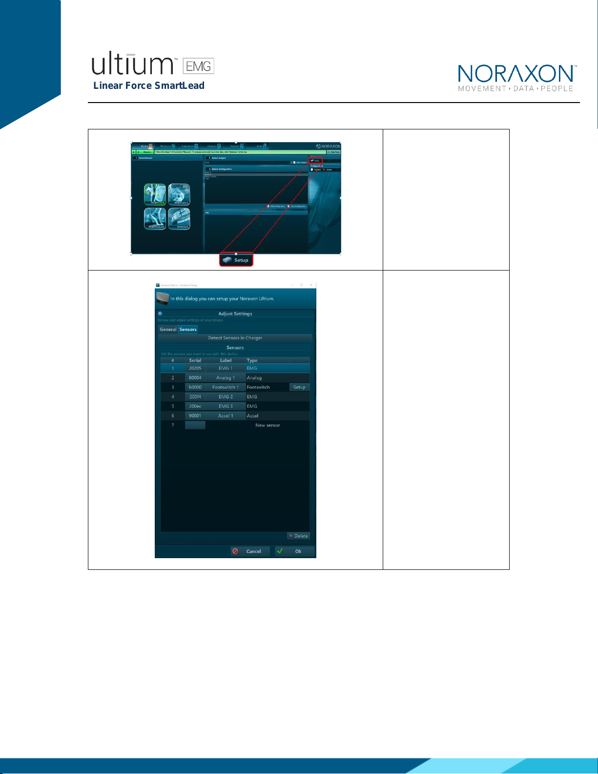
Step 1
Enter the Hardware Setup
screen and setup the
Noraxon EMG system in
accordance with its
provided hardware
manual.
Step 2
Click ‘Detect Sensors in
Charger’ (All sensors which
you would like to use must
be in the charger) –this
will add the SmartLead(s)
to the list of sensors (only
if the unique SmartLead is
connected to their
corresponding sensor). If
the unique SmartLead (ex:
Linear Force) is not
connected to the
corresponding sensor
during detection, MR3 will
assume you are using the
sensor to collect EMG
data. Click OK.
Linear Force SmartLead
P-802 Rev B (May 2019)
11
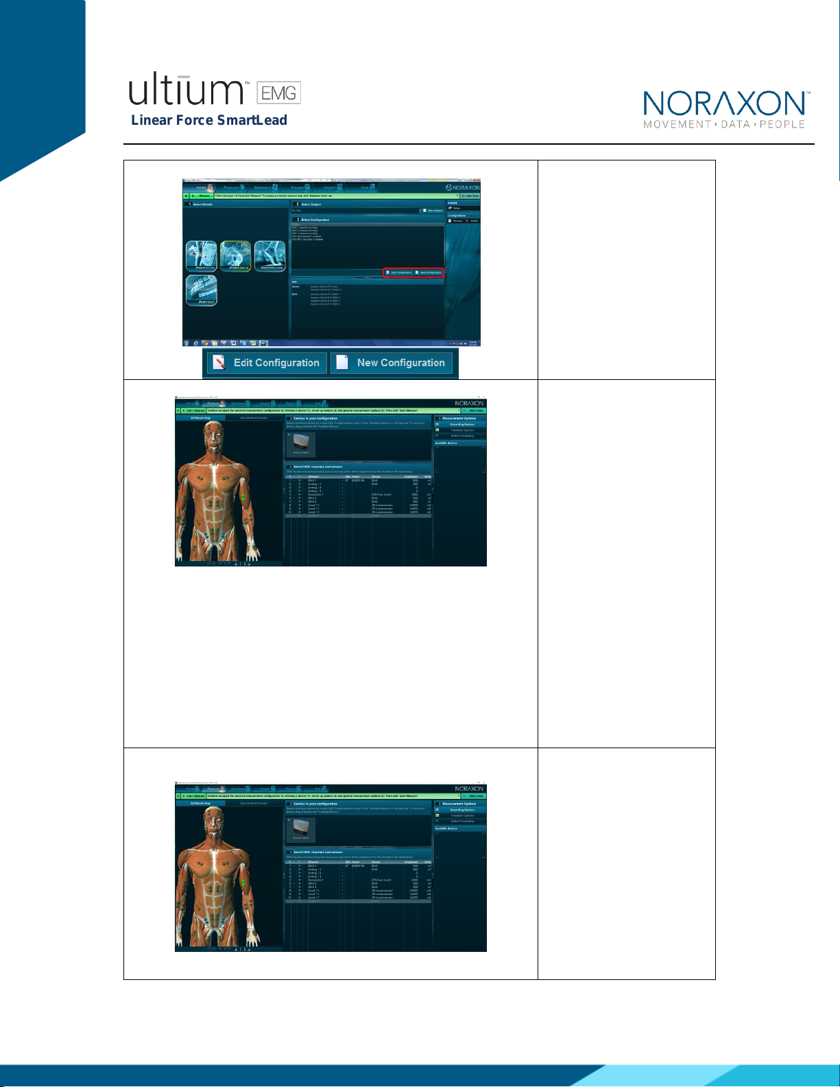
Step 3
Once back in the Home
screen, choose to create a
new or edit an existing
configuration.
It is recommended that you redetect sensors in the hardware
configuration every time the SmartLeads are removed from the
Ultium sensor (redetection is necessary to revert to the use of the
sensor’s EMG functionality). This will prevent configuration errors
leading to the inability to collect a measurement. If an error
message pops up when starting a measure, and you are using
SmartLeads, this is a good first troubleshooting step (1. Redetect
sensors in hardware set-up; 2. Double check the configuration). *
See Find My Sensor section below
Step 4
In the measurement setup
screen, insert the Ultium
system into the Devices in
your configuration box.
Step 5a
Once the Ultium system is
inserted, the muscle map
will appear to the left, and
the EMG channels and
sensors will appear below.
The Ultium Linear Force
should automatically
appear, as detected by the
Ultium system (if it does
not –refer back to step
2a).

Linear Force SmartLead
P-802 Rev B (May 2019)
12
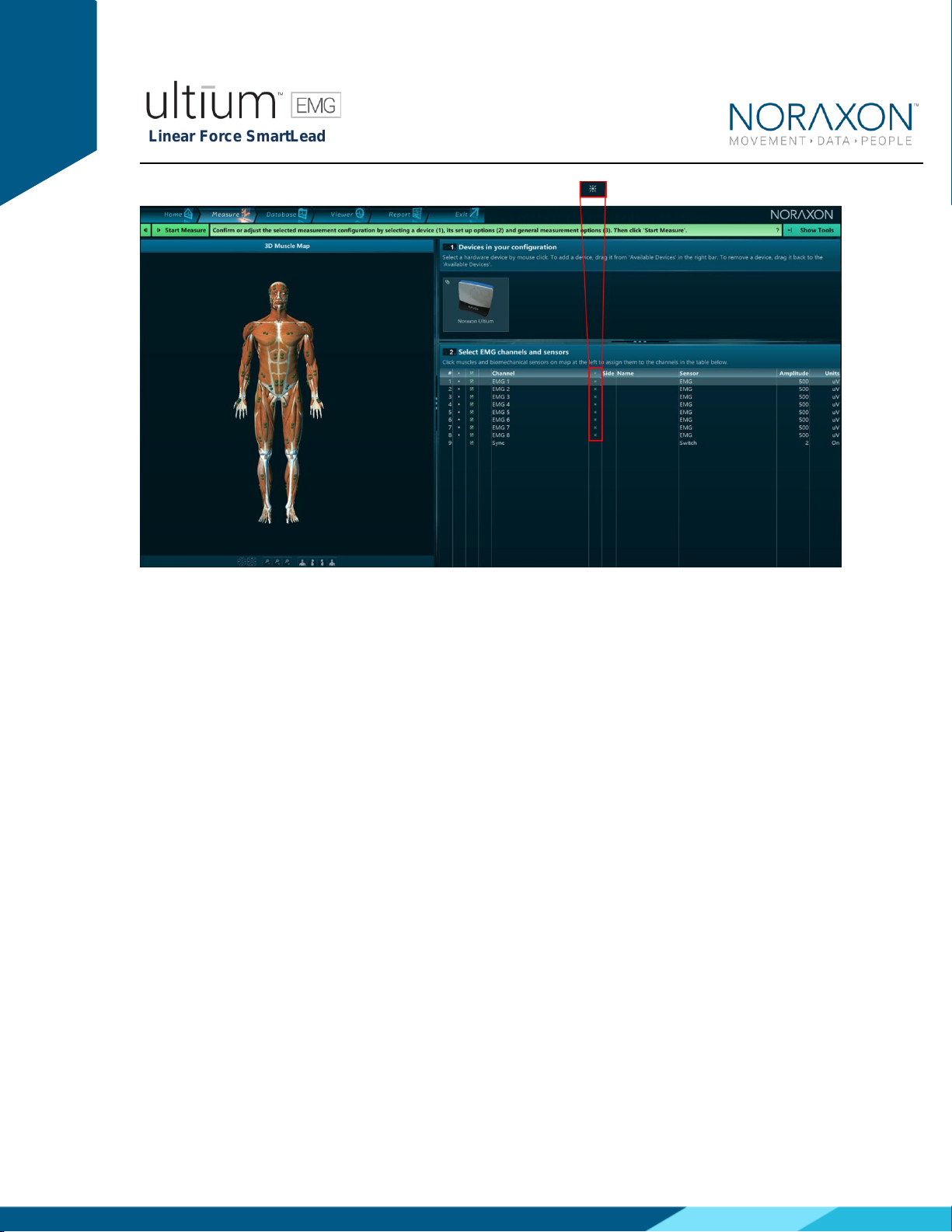
To select the Linear Force
for use in a recording,
check the box next to the
Footswitch channel to be
recorded.
Step 5b
Continue with the
measurement setup as
described in the Noraxon
system’s hardware
manual.
6.6.2 Find My Sensor Feature
Allows the user to quickly locate a specified Ultium sensor while creating/editing a MR3
configuration (refer to section 7 for guidance on how to create or edit a configuration). If one of the
stars (refer to the figure below) is clicked, the corresponding sensor will repeatedly blink light purple
in bursts of 3. If the topmost star is clicked, every sensor that is currently in the configuration will
execute the same blinking pattern.
Linear Force SmartLead
P-802 Rev B (May 2019)
13
If a SmartLead is connected to a sensor when the sensors are detected in the MR3 hardware setup
(Section 6 -> MR3 Configuration) it will override the EMG functionality of that sensor. Therefore, if
the SmartLead is moved to a new sensor, Step 1-5 of Section 6 (MR3 Configuration) must be
recompleted.
To check if the SmartLeads are currently connected to the proper Ultium sensor, the Find My
Sensor feature may be useful. Click the topmost star (shown in the above figure). If all lights blink
(white color), then they are properly connected. If one of the sensors blinks (red color), the
SmartLead that is connected to this sensor should be connected to another sensor. It is
recommended to recomplete Steps 1-5 of Section 6 above if this does occur.
7.1 Normal Appearance of Signals
The sensor’s STATUS LED provides a means of communicating its operational state. In the idle
state, the STATUS LED will flash blue at a low, once per second rate. When the sensor is actively
measuring a signal, the STATUS LED will flash recognizably faster (green).
Quick Testing:
To ensure that the Ultium Linear Force SmartLead is measuring properly when connected to the
Ultium Sensor and attach a known weight to the Linear Force sensor. Verify that the signal shows
the same force as the known force.
7 Pre-Use Check-Out

Linear Force SmartLead
P-802 Rev B (May 2019)
14
8 Operating Instructions
8.1 Safety Information Summary
Strictly follow all safety practices given in section 4 of this manual. The most critical ones are
repeated here.
CAUTIONS
•Never use the Noraxon Ultium System on a person with an implanted pacemaker
•Never operate the Noraxon Ultium System within 1 meter of any critical medical device
8.2 Normal Functions with Interface to a PC
When used with the companion software the Linear Force SmartLead will display and record a
signal in lbf.
Consult the user manual for the companion software for descriptions of the setup, playback and
analysis of the data acquired by the Ultium system.
8.3 Exceptional Functions/Situations (error messages)
Please see the appropriate Noraxon system’s hardware manual for possible error messages.
8.4 Shutdown after Use
At the end of the day:
•Place all EMG sensors inside the sensor docking station(s).
•Tap the Sensor Power touch button on the Receiver to power all sensors off.
8.5 Storage and Protecting Between Usages
For extended storage or when travelling:
•Place all sensors into the sensor docking station and power them off (Slide your finger
across the sensor power touch button. When the sensors are shutdown they will stop
blinking completely. The sensors are reactivated by briefly charging them).

Linear Force SmartLead
P-802 Rev B (May 2019)
15
•Position all components inside the system travelling case according to their prepared
cavities. (see photo below)
9 Accessories and Optional Modules
9.1 Accessories
The Linear Force SmartLead does not have any corresponding accessories.
10 Cleaning
10.1 Safety Precautions When Cleaning
WARNING
Only use a damp cloth with mild soap and water or isopropyl alcohol to clean the bottom of
the Ultium Sensors.
Do not immerse Ultium Sensors in any water or liquid.
Linear Force SmartLead
P-802 Rev B (May 2019)
16
11 Maintenance
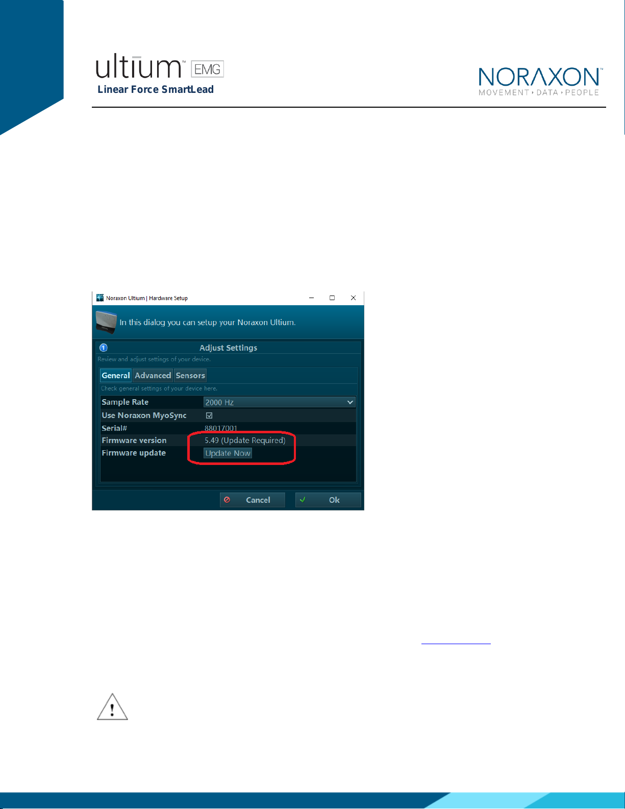
11.1 Device Software (firmware) updates
The internal program (firmware) inside the various Ultium devices can be updated via MR3. The
user will be notified within the Ultium System hardware setup if an update is required. Ensure that
all sensors are placed in the Ultium charging doc and that the charging doc is connected to the
Ultium receiver prior to initiating the firmware update. If you start the update prior to completing
this step, you may need to update again (firmware update button will still be present in hardware
setup).
11.2 Maintenance by Qualified Individuals
The following activities should only be undertaken by PC support (IT) personnel, equipment
technicians or those with suitable training.
11.3 Companion Software Updates
•Perform a backup of the data folders to a separate drive as a precaution.
•Click on the Patch/Update link provided in the email or as given on the Noraxon website.
•Download the Patch/Update file.
•To install the Patch/Update, click “Run” on the dialog box. No password is required.
Attention
Table of contents
Other Noraxon Accessories manuals


Popular Accessories manuals by other brands


Sygonix
Sygonix FS1 operating instructions

Tefcold
Tefcold CKC8 Technical manual

KROHNE
KROHNE SMARTPAT PH 8 Series Supplementary instructions

Lucky Reptile
Lucky Reptile Thermo Socket PRO operating instructions

WATTECO
WATTECO BoB Assistant Reference manual

Siemens
Siemens SIMATIC VS130-2vcr installation instructions