Troubleshooting
Troubleshooting
Thissectionwilldiscussvariousissuesthatmayoccur,
whatcausesthem,andwhatpossiblesolutionsare.
1) No status LEDs turned on in Diagnostic Cockpits.
Checkinputmains ACpowersupply andinternal
wiring.
- ConrmthattheACpowerissecurelyconnected
toterminalsL1&N.
- Withamultimeter,measurethephase-to-phase
ACvoltage(L1-N).Voltagereadingsshouldbe
between200and240VAC.
oIfthevoltagesarenotmeasuredasindicated,
inputpowermustbe adjustedtoreectthe
abovespecications.
2) Drive Status LED1 flashing red, green off.
SK200Eisfaultedandtripneedstobecleared.
- Thenumber oftimes theLED ashes beforea
pauseindicatestheerrorcode.Example:LED1
ashes red 3 times before a pause. This indi-
cateserrorcode3whichmeansanovercurrent
faulthasoccurred.Theerrorcode,description,
andremediescanbefoundinsection7.2ofthe
SK200EoperationmanualBU0200.
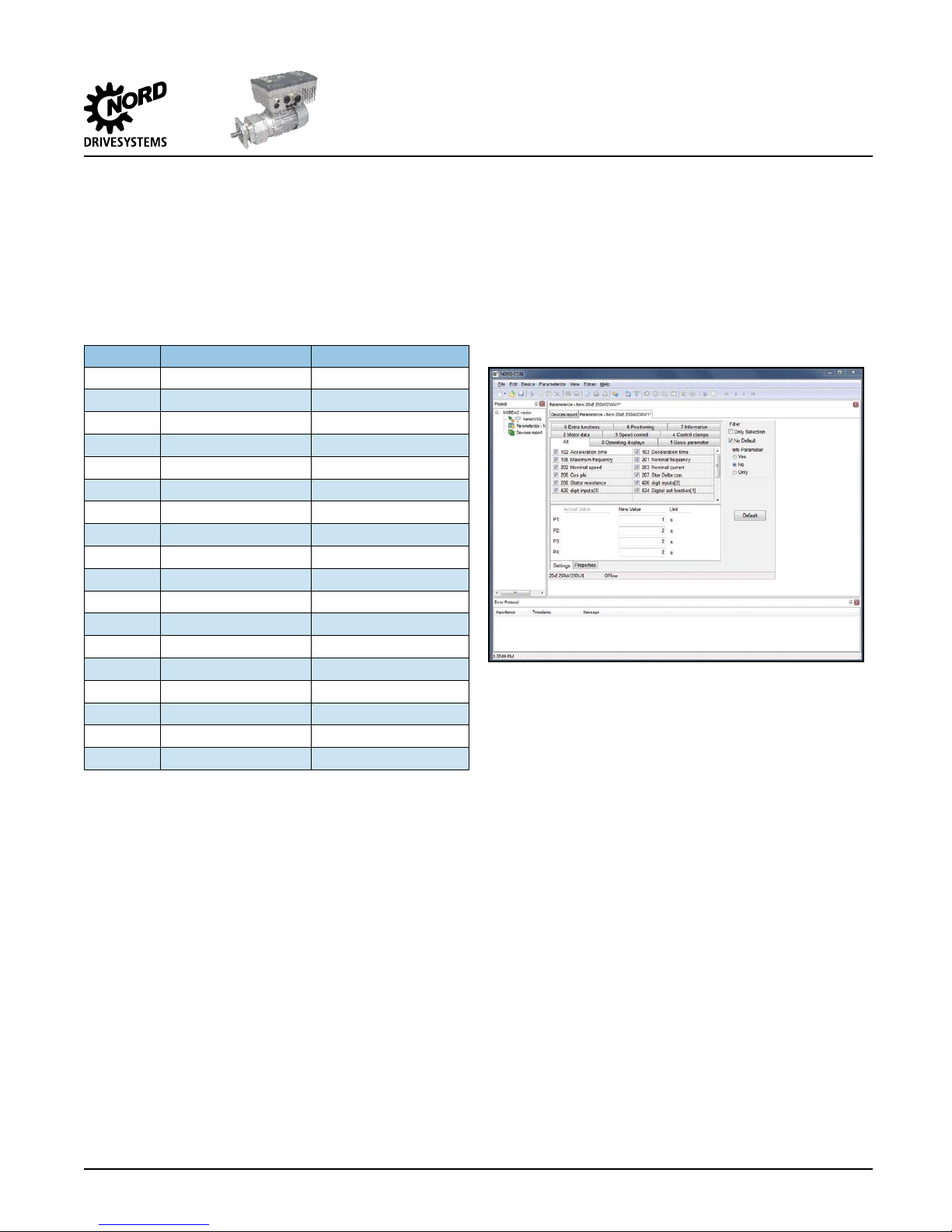
- UsingeithertheNORDCONsoftwareortheSK
PAR-3Hparameterbox,theerrorcodecanalso
be determined by observing parameter P700
[-01] – Current Fault. Parameter P700[-01] is
locatedintheInformationparametergroup.
- TheconditionsthatcausedtheSK200Etofault
mustbeclearedbeforethedrivemaybestarted
again.
3) Drive Status LED1 flashing green slowly (standby
mode) but will not run when given enable
command.
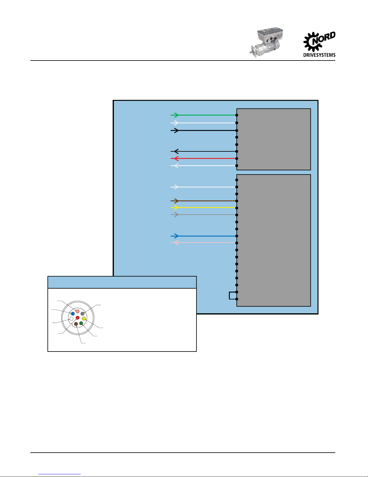
Digital inputs 1 & 2 may not be wired and/or
conguredproperly.
- Check wiring of M12 receptacle. Conrm the
yellowwireisproperlyconnectedtoterminal21
and the grey wire is properly connected to
terminal 22.
- Conrm digital input parameters (Control
ClampsGroup)areconguredproperly.
oParameterP420[-01]:1-Enableright
oParameterP420[-02]:3-Phaseseq.reversal
- CheckparameterP708(Informationgroup)for
statusofdigitalinputswhilethecontrolpanelis
sendingenablecommands.
oIf using NORDCON, the status window does
not automatically update when the digital
input state changes. Press “Read” button
toupdatestatuswindow.Activeinputswill
haveacheckmarkdisplayed.
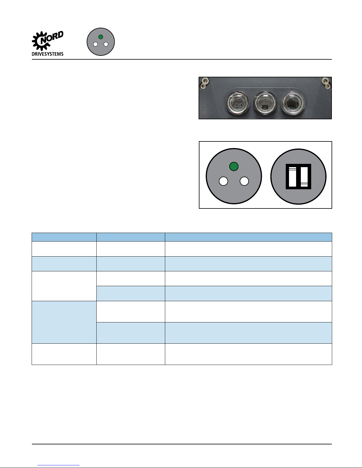
oIfusingtheSKPAR-3Hhandheldprogramming
tool,thedigitalinputstatewillautomatically
be displayed when changed. Active inputs
willbedisplayedasa“1”andinactiveinputs
willbedisplayedas“0”.Digitalinput1&2
willbeshownasthe1stand2nddigitsfrom
therightsideofthedisplayrespectively.The
5thdigitshouldalwaysshow“1”.Figure13
showsthisstate.
Figure 13 - State of Digital Inputs, P708
- Iftheinternalwiringiscorrectandifthestatus
ofparameterP708doesnotshowtheseinputs
as active, check external control wiring and
control.