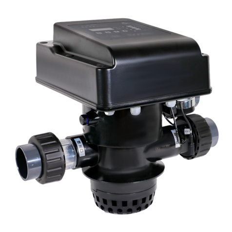
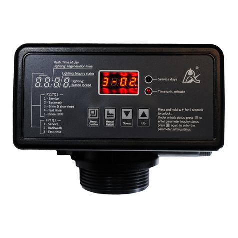
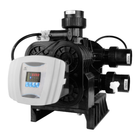
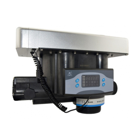
Runxin 51215 User manual

MODEL F77BS-51215/F77AS-61215/F77CS-71215
Multi-functional Flow Control Valve for
Water Treatment Systems
51215 (Old Model No.: F77BS)
61215 (Old Model No.: F77AS)
91215 (Old Model No.: F77CS)
Instruction Manual
Please read this manual in details before using the valve
and keep it properly in order to consult in the future.
0WRX.466.506
International Patent Public No.:
WO 2006/007772
China Patent No.: ZL02220153.X,
ZL200420078956.5
USPatentNo.: 7549446
India PatentNo.:232582
Russia Patent No.:2349819
South KoreaPatentNo.:10-0914137
Mexico Patent No.: 268581
Australia Patent No.: 2005263257
Philippine Patent No.: 1-2006-502553
Taiwan Patent No.:M287896

MODEL F77BS-51215/F77AS-61215/F77CS-71215
Before the valve put into use, please fill in the below content so as to
help us to refer in the future.
Softener System Configuration
Tank Size:Dia. mm,Height mm;
Resin Volume L;Brine Tank Capacity L;
Hardness of Raw Water mmol/L;
Pressure of Inlet Water MPa;
Control Valve Model ;Number ;
Water source: Ground-water□ Filtered Ground-water □Tap Water □
Other .
Parameter
Backwash min.;Brine & Slow Rinse Time min.;
Brine Refill Time min.;Fast Rinse Time min.;
The Specification of Drain Line Flow Control ;
Injector No. .
If there is no special requirement when product purchase, we
choose 3# injector for the standard configuration.


MODEL F77BS-51215/F77AS-61215/F77CS-71215
Catalogue
Notice ...........................................................................................................
1. Product Overview.....................................................................................
1.1. Main Application & Applicability.....................................................
1.2. Product Characteristics..................................................................
1.3. Service Condition...........................................................................
1.4. Product Structure and Technical Parameters................................
1.5. Installation......................................................................................
2. Usage.......................................................................................................
2.1. Hand wheel....................................................................................
2.2. Indicator.........................................................................................
2.3. Figure on Decoration Cover and its English Description...............
3. Applications..............................................................................................
3.1. Working Flow Chart .......................................................................
3.2. System Configuration and Flow Rate Curve.................................
3.3. Parameter Settlement....................................................................
3.4. Trial Running..................................................................................
3.5. Usage.............................................................................................
3.6. Trouble-Shooting............................................................................
3.7. Spare Part and Part No..................................................................
4. Warranty Card..........................................................................................

MODEL F77BS-51215/F77AS-61215/F77CS-71215


MODEL F77BS-51215/F77AS-61215/F77CS-71215
1
Notice
To ensure normal operation of the valve, please consult with
professional installation or repairing personnel before use it.
If there are any of pipeline engineering and electric works, there must
be finished by professional at the time of installation.
Do not use the control valve with the water that is unsafe or unknown
quality.
Depending on the changing of working environment and water
requirement, each parameter of softener should be adjusted accordingly.
When the water treatment capacity is too low, please check the resin. If
the reason is shortage of resin, please add; if the resin is turn to reddish
brown or broken, please replace.
Test water periodically to verify that system is performing satisfactorily.
During softener process, sodium is regarded as a part of edible salt. If
you are sodium limited intake person, please contact doctor.
Sodium used in the water softening process should be considered as
part your overall dietary salt intake. Contact doctor if you are on a low
sodium diet.
Do not put the valve near the hot resource and do not leave it outside.
Forbidden to use the brine tube or other connectors as support to carry
the system.
Please use this product under the water temperature between 5~50℃、
water pressure 0.2~0.6 MPa. Failure to use this product under such
conditions voids the warranty.
If the water pressure exceeds 0.6Mpa, a pressure reducing valve must
be installed before the water inlet. While, if the water pressure under 0.2
MPa, a booster pump must be installed before the water inlet.
Do not let children touch or play, because carelessness operating may
cause the procedure changed.
We advise you to use M88×2 distributors. It is easy for disassembly.

MODEL F77BS-51215/F77AS-61215/F77CS-71215
2
1. Product Overview
1.1. Main Application & Applicability
Used for softening, demineralization or filtration water treatment systems
F77AS (DF for regeneration), suitable for
Ion exchange equipment, the raw water hardness ≤6.5mmol/L.
Boiler softening water system
RO pretreatment softening system, etc.
F77BS (Filtration),suitable for
swimming pool filter system.
Filtration system
Activated carbon filter or sand filter of RO pretreatment system.
F77CS (Floating bed)
Ion exchange equipment, the raw water hardness <
15mmol/L.(When it used as UF regeneration in boiler softening
water system, the raw water hardness ≤6.5mmol/L)
Boiler softening water system
RO pretreatment softening system, etc.
1.2. Product Characteristics
Simple structure and reliable sealing
It adopts hermetic head faces with high degree pottery and corrosion
resistance for opening and closing. It has two valve cores. One controls
inlet water, the other controls outlet water.
No water pass the valve in regeneration in single tank type.
Brine refill controlled by manual ball valve. (F77AS/61215,
F77CS/91215)
During service, manual ball valve will control to start the brine refill, in
order to shorten the regeneration cycle time.
Two ways for installation
Use side-mounted connector to change the valve from top-mounted
to side-mounted.
F77CS can be installed in top mounted or side mounted. (When

MODEL F77BS-51215/F77AS-61215/F77CS-71215
3
side-mounted connector TOP side connected with top strainer, BOTTOM
side connected with side bottom strainer) It’s up-flow for regeneration. If
connector with side-mounted in upside down (TOP side connector with
bottom strainer, BOTTOM side connected with top strainer) It’s for floating
bed system.
For filtration system
Drain outlet is the same size as water outlet. Block the brine line
connector change the valve to F77BS filter valve.
1.3. Service Condition
Runxin Valve should be used under the below conditions:
Items
Requirement
Working
conditions
Water pressure
0.2 MPa~0.6 MPa
Water temperature
5℃~50℃
Working
environment
Environment
temperature
5℃~50℃
Relative humidity
≤95%(25℃)
Inlet water
quality
Water turbidity
Softener (F77AS,F77CS)<2FTU;
Filter (F77BS) <20 FTU
Water hardness
First Grade Na+<6.5 mmol/L;
Second Grade Na+<10 mmol/L
Floating bed (F77CS)<15 mmol/L
Free chlorine
<0.1 mg/L
Iron2+
<0.3 mg/L
CODMn
<2 mg/L(O2)
In the above table, First Grade Na+ represents First Grade Na+
Exchanger. Second Grade Na+ represents Second Grade Na+
Exchanger.
When the water turbidity exceeds the conditions, a filter should be
installed on the inlet of control valve.
When the water hardness exceeds the conditions, the outlet water

MODEL F77BS-51215/F77AS-61215/F77CS-71215
4
hardness will hardly reach the requirement of boiler feed water(0.03
mmol/L). It is suggested to adopt second grade softener.
1.4. Product Structure and Technical Parameters
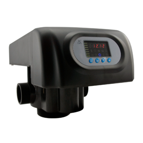
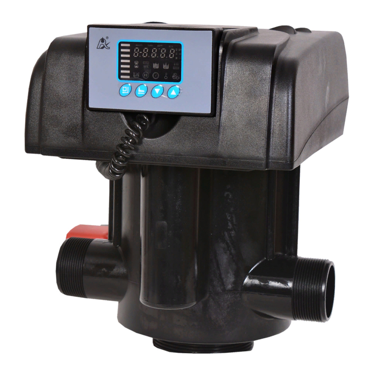
A. Product Dimension (The appearance is just for reference. It is
subjected to the real product.)
F77AS has the same appearance as F77CS. Block the drain line
connector, it will become F77BS.

MODEL F77BS-51215/F77AS-61215/F77CS-71215
5
B. Technical Parameter
Model
Connector size
Flow
Rate m3/h
@0.3MPa
Remark
In/Outlet
Drain
Outlet
Brine Line
Connector
Base
Riser Pipe
F77AS
61215
2″M
2″M
3/4″F
4″-8UN
1.5″D-GB(50mm)
18
DF
softener
F77BS
51215
2″M
2″M
/
4″-8UN
1.5″D-GB(50mm)
18
Filter
F77CS
91215
2″M
2″M
3/4″F
4″-8UN
1.5″D-GB(50mm)
18
UF
floating
bed
Remark: M—Male F—Female OD—Outer Diameters
1.05OD=26.7mm
Above flow rate is the maximum flow rate which tested under pressure
drop 0.3MPa.
F77CS can be used as floating bed. But at the same time it only can
be side-mounted with the connector in upside down.( TOP side connector
with bottom strainer, BOTTOM side connected with top strainer)
1.5. Installation
A. Installation notice
Before installation, read all those instructions completely. Then obtain
all materials and tools needed for installation.
The installation of product, pipes and circuits, should be
accomplished by professional to ensure the product can operate normally.
Perform installation according to the relative pipeline regulations and
the specification of Water Inlet, Water Outlet, Drain Outlet, and Brine Line
Connector.
B. Device location
①The softener should be located close to drain.
②Ensure the unit is installed in enough space for operating and

MODEL F77BS-51215/F77AS-61215/F77CS-71215
6
maintenance.
③Brine tank need to be close to softener.
④The unit should be kept away the heater, and not be exposed outdoor.
Sunshine or rain will cause the system damage.
⑤Please avoid to install the system in one Acid/Alkaline, Magnetic or
strong vibration circumstance, because above factors will cause the
system disorder.
⑥Do not install the filter or softener, drain pipeline in circumstance which
temperature may drop below 5℃, or above 50℃.
⑦One place is recommended to install the system which cause the
minimum loss in case of water leaking
C. Pipeline installation (Take F77AS side-mounted as a sample)
①Install control valve
a. As the Figure 1-1 shows , glue the riser pipe to the bottom strainer and
put it into the mineral tank.
b. Fill the mineral to the tank, and the height is accordance with the design
code. Install the top distributor to the valve.
c. Use DN50 UPVC pipe to connect side-mounted connector with top and
bottom strainers. (TOP side connector with top strainer, BOTTOM side
connected with bottom strainer)
d. Connect valve with side-mounted connector. Use steel fork to adjust
position of the valve, which makes the inlet/outlet pipe line straight to up
or down.

MODEL F77BS-51215/F77AS-61215/F77CS-71215
7
Note:
●Avoid floccules substance together with resin to fill in the mineral
tank.
●Avoid O-ring inside control valve falling out while rotating it on the
tank.
②Pipeline connection
a.As Figure1-2 shows, install a disc filter in the inlet.
b.Install sampling valves in inlet、outlet and pipeline A.B.C. as showed in
Figure 1-1.
c. Use DN50 UPVC for system inlet pipe line and valve inlet. Put the flow
meter in the valve outlet. Use DN50 UPVC connector system outlet with
flow meter.

MODEL F77BS-51215/F77AS-61215/F77CS-71215
8
Note:
●If use welded copper pipe for inlet/outlet pipeline, the pipeline
should be welded first. Then connect to valves. The high
temperature will make the plastic pipe broken.
●Don’t use too much strength to screw the pipe line. Keep the pipe
line in right place to connect with valve.
●During installation, keep the inlet/outlet pipeline in parallel. And
pipeline should be fixed.
③Install drain pipeline (If no special requirement, the standard DLFC is
No.7703)
a. Based on the table P14, for F77AS, if tank diameter is 900mm, install
step d. And use the matched DLFC. If the tank size bigger then 900mm,
you need to ask supplier for another DLFC which doesn’t drill hole. Install
it as below steps.
b. According to matched tank diameter size, to drill φ6 hole on the
corresponding quantity of DLFC.
c. Insert drain line flow control into drain hose connector, then crew it into
drain outlet, and lock it.
d. Glue the drain outlet with UPVC (DN40). Put drain outlet pipe to sewer
as showed in the Figure 1-2.

MODEL F77BS-51215/F77AS-61215/F77CS-71215
9
For filter valve F77B, there is no DLFC, install UPVC (DN40)
according to procedure d.
Note:
● Control valve should be higher than drain outlet, and be better not
far from the drain hose.
● Be sure not connect drain with sewer, and leave a certain space
between them, avoid wastewater be absorbing to the water
treatment equipment, such as showed in the Figure1-2.
④Connect brine tube
As Figure1-2 shows, use UPVC (DN20) to connect brine valve with
brine line connector.
Note:
Keep brine line short and smooth. Elbow no more than four to
avoid bad brine.
Brine valve must be installed.

MODEL F77BS-51215/F77AS-61215/F77CS-71215
10
2. Usage
2.1. Hand wheel
As Figure shows, the valve needs one hand wheel to operate two
indicators in anticlockwise, which to realize backwash, brine & slow rinse
or fast rinse functions.
2.2. Indicator
A. F77BS/51215, F77AS/61215
State
Indicator Position
F77BS
F77AS
Service
Service
Brine
Refill

MODEL F77BS-51215/F77AS-61215/F77CS-71215
11
Backwash
Backwash
/
Brine &
Slow
Rinse
Fast
Rinse
Fast
Rinse
B. F77CS/91215, Floating bed
State
Indicator Position
F77CS
Floating
Bed
Service
Brine
Refill
Service
Brine
Refill

MODEL F77BS-51215/F77AS-61215/F77CS-71215
12
/
Settling
Bed
Close water inlet
Backwash
/
Brine &
Slow
Rinse
Brine &
Slow
Rinse
Fast
Rinse
Fast
Rinse
2.3. Figure on Decoration Cover and its English
Description
English
Figure
Description
SERVICE
In service state
BACKWASH
In backwash state
BRINE&SLOW R.
In brine & slow rinse
state
BRINE REFILL
In brine refill state
FAST RINSE
In fast rinse state

MODEL F77BS-51215/F77AS-61215/F77CS-71215
13
/
Remark: and
two working positions,
ensure ball valve is
opened and be closed
at other working position
by manually.

MODEL F77BS-51215/F77AS-61215/F77CS-71215
14
3. Applications
3.1. Working Flow Chart
For filter valve only has service, backwash and fast rinse.
This manual suits for next models
5
Table of contents
Other Runxin Control Unit manuals
Popular Control Unit manuals by other brands

Okin Refined
Okin Refined JLDP.15.005.501 user manual

Kollmorgen
Kollmorgen MKD Series installation manual

Advantech
Advantech WISE-4610 Series Startup manual

ICP DAS USA
ICP DAS USA I-8124W user manual

DMP Electronics
DMP Electronics 867 Style W installation guide

Estyma
Estyma Control M RS 420 Operation manual