Norden NVS-IP30008PM User manual

NVS-IP30008PM
Wall Mounted IP Based Paging Station
User Manual

1
1. About Network PA System
Network public address is a computer network technology based modular structured and highly integrated
and intelligent public address system. The system realizes digital transmission and takes LAN as its
transmission medium, and the transmission distance may be over a dozen kilometres. The existing LAN
architecture can be used so that projects adopting the device can be constructed quickly and efficiently. It
realizes fusion of multiple networks and breaks the limitations that traditional public address systems can
only realize download and can be only controlled at the computer room, by providing powerful interactive
functions.
The network public address device is compatible with terminals with various functions, including player
terminals, VOD terminals, paging terminals and one-button emergency calling terminals etc. The device is
composed of a player, a zoning mechanism, a timer, and an equalizer; in addition, it also provides powerful
audio matrix function. The network public address system is applicable to airports, wharves, college towns,
schools, large gatherings (such as the Expo Park), gymnasium, industrial parks, parks, rail transit and
expressways, etc.
1.1 Device Description
NVS-IP30008PM is a network high-fidelity wall-mounted intelligent paging station is a on TCP/IP
transmission protocol, which can be connected to anywhere in the network . With the characteristics of
the high stability of the traditional paging station, the operation is stable and reliable, and the failure rate
is low. 7-inch true colour LCD touch screen control & graphical user interface is more user-friendly. It has
auxiliary input & output option for audio input & output.
1.2 Features
Support 100/10Mbps adaptive TCP/IP network transmission protocol.
Inbuilt 7-inch true colour touch screen, aluminium alloy drawing industrial panel design.
Wall-mounted and embedded design.
Adopt high fidelity and handheld mobile microphone design.
Audio level indication.
With manual shortcut keys to make quick paging in critical situations.
Built-in 1W monitoring speaker, to pre-listen audio before broadcasting
Inbuilt 1-channel input (can be extended external program source, wireless microphone etc),
1-channel local line output (can be offline output local power amplifier paging), 1-
channelauxiliary line output (extended listening power).
Interactive & simple graphical interface.
Built-in high-fidelity large dynamic range of AGC processing circuit.
Built-in high-performance DSP sound processing circuit.
Adopt embedded real time system platform, adopt high performance ARM processor.
Can edit network playback terminal group.
Built-in chime.
2
Can play network host program library songs.
With the audio logging function, the paging content can be recorded in real time, and can be
played later.
User password and rights management option.
2. Appearance
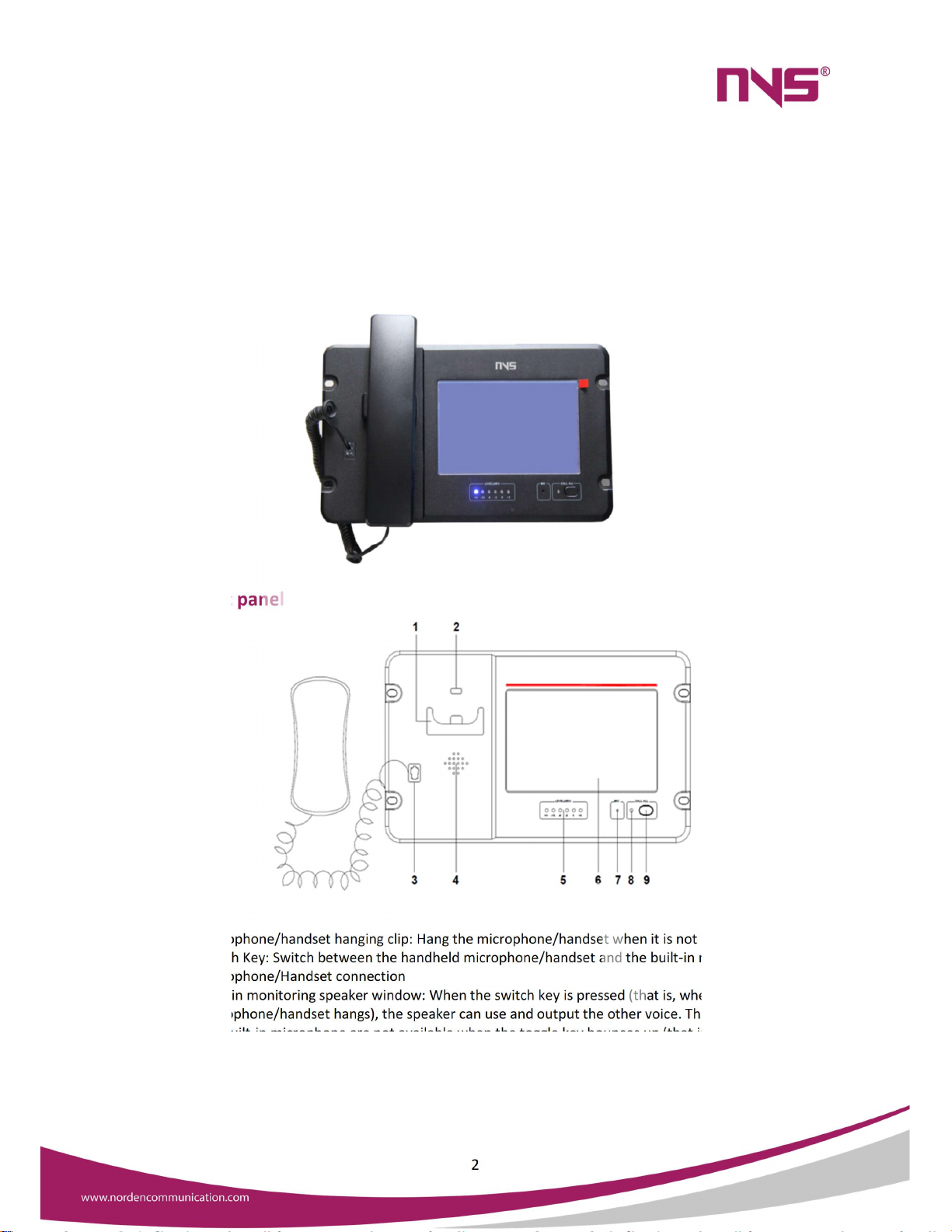
2.1 Front panel
1. Microphone/handset hanging clip: Hang the microphone/handset when it is not in use.
2. Switch Key: Switch between the handheld microphone/handset and the built-in microphone.
3. Microphone/Handset connection
4. Built-in monitoring speaker window: When the switch key is pressed (that is, when the handheld
microphone/handset hangs), the speaker can use and output the other voice. This speaker and
the built-in microphone are not available when the toggle key bounces up (that is, when the
handheld microphone/handset is picked up).
5. Output Level Indicator: The larger the output volume, the more the level indicator group is lit.
6. LCD True Colour: Display the working status and interface of the pager, and the touch screen
allows for options.

3
7. Built-in microphone: When the switch key is pressed (that is, the handheld microphone/handset
hangs), the built-in microphone will be automatically opened, you can aim at the microphone to
speak to each other, the built-in speakers will output the other voice.
8. One-click Paging Indicator: Press the one-click paging button the LED is lit and all zones are
paged.
9. One-click Paging on/off Button: Press this button to make a full area paging/closing.
2.2 Rear Panel
1. Power switch
2. Built-in monitoring audio signal output interface: Can connect the 1W speaker device or
monitoring headset device, and the monitoring volume is locally adjustable.
3. Line Audio Input interface: To connect the player devices, such as a DVD player or tuner.
4. Line Audio Output interface: Connect the power amplifier device.
5. Monitor Volume Control knob: Adjust headset monitoring volume, rotate clockwise to increase
and rotate counter-clockwise to decrease the volume.
6. Line output Volume adjustment knob: Rotate clockwise to increase the volume, and counter-
clockwise to reduce the volume.
7. Microphone Volume Control knob: Used to adjust the microphone volume rotate clockwise to
increase the volume, and rotate counter-clockwise to reduce the volume.
8. AC220VPower Input Cable
9. Monitor Headphone jack
10. USB interface: Used to upgrade firmware.
11. Network interface.
12. RS232 interface for remote control & debugging.
13. Interface for future expansion
4
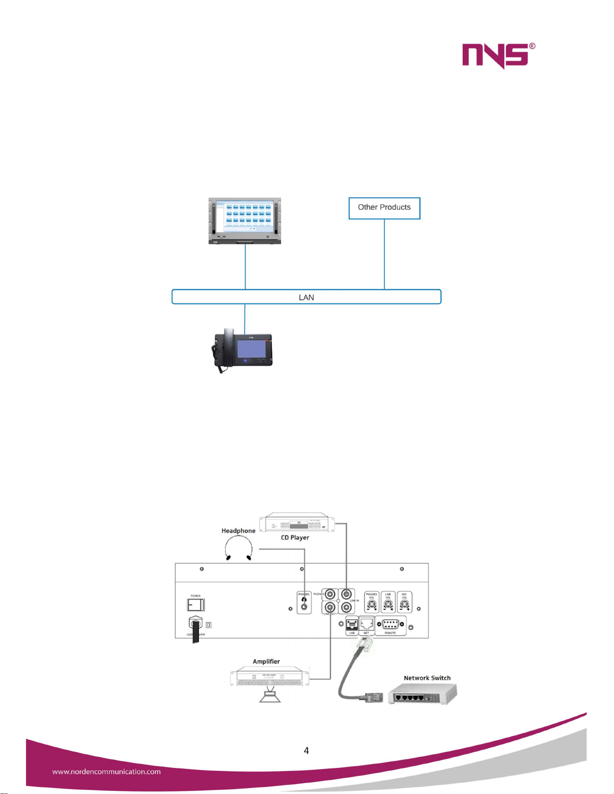
3. Connection
3.1 Network Connection Diagram
The paging microphone, Server & other devises must be in the same network
3.2 Device connection Diagram
The line in connection can be used to connect local audio inputs such as CD player FM tuner etc. The audio
from these local audio sources can be transmitted to network using this paging microphone. Headphones
can be connected Phones jack & line out can be connected to Active monitor speaker or amplifier

5
4. Operation
Plug the device into power source after making necessary connections, then turn on the power switch on
the rear panel
4.1 Power-on Interface & main menu
After successful boot, the system will initialize the settings and will display "Starting, please wait ...",
during which the system will load the information of the last run of this paging station, and so on, after
around 25 seconds it display the login interface as shown in the below image
In this window, the user can enter the username & password to login into main menu. By default, there is
no password for the admin User, it can be set in the settings menu.
After the successful login, it will navigate to the following page:

6
All controls can be one in this menu. All the output devices connected to the system will be displayed
here. To control a device, it is mandatory to select that device / group. Then it is possible to make
announcement, select audio source, Control volume etc.
4.2 Zone Status Display
Displays the current working status of each in this menu, such as the zone name, current work task/status,
volume level etc. All the devices shown in blue will be online grey will be offline if the paging mic is
connected to network.
For example: In the following figure 191.168.79.104 is offline.
"192.168.79.104" is the name or the area code of this zone & that can be edited.
"Offline" is the status of this zone, If the device is online, it will display the current task such as
“Paging”, “Alert”, etc.
"Volume 50%" for the current volume level of the zone.
7
4.3 Zone Paging
To call paging a zone:
In the first step, touch the "Zone Call" icon on the upper right side of the main interface,
then touch and select the zone to be called (a selected zone will be surrounded by red
box), and then touch the "Call" button to start the calling or touch “Talking” button to
start the intercom. The message "Calling" will be displayed on the zone which is being
called. Press the "Stop" button to stop the calling and the zone will restore to its previous
status.
To paging all zones, touch and select the "Zone Call" button on the upper right side of the
main interface, then touch the "Select all" button to select all zones and then touch the
"Call" button to call all zones. Touch the "Stop" button to stop the calling.
Note: In the zone paging state, if you press the “Chime” button, the system will emit a chime tone, so that
the listeners pay attention to the speakers.
4.4 Group Paging
To call a group:
In the first step, touch the "Group Call" icon on the upper right side of the main interface,
then touch and select the group to be called (a selected group will be surrounded by white
box), and then touch the "Call" button to start the calling. Press the "Stop" button to stop
the calling and the group will restore to its previous status.
To call all zones, touch and select the "Group Call" button on the upper right side of the main
interface, then touch the "Select all" button to select all groups and then touch the "Call"
button to call all groups. Touch the "Stop" button to stop the calling.
Note: In the zone paging state, if you press the “Chime” button, the system will emit a chime tone, so that
the listeners pay attention to the speakers.
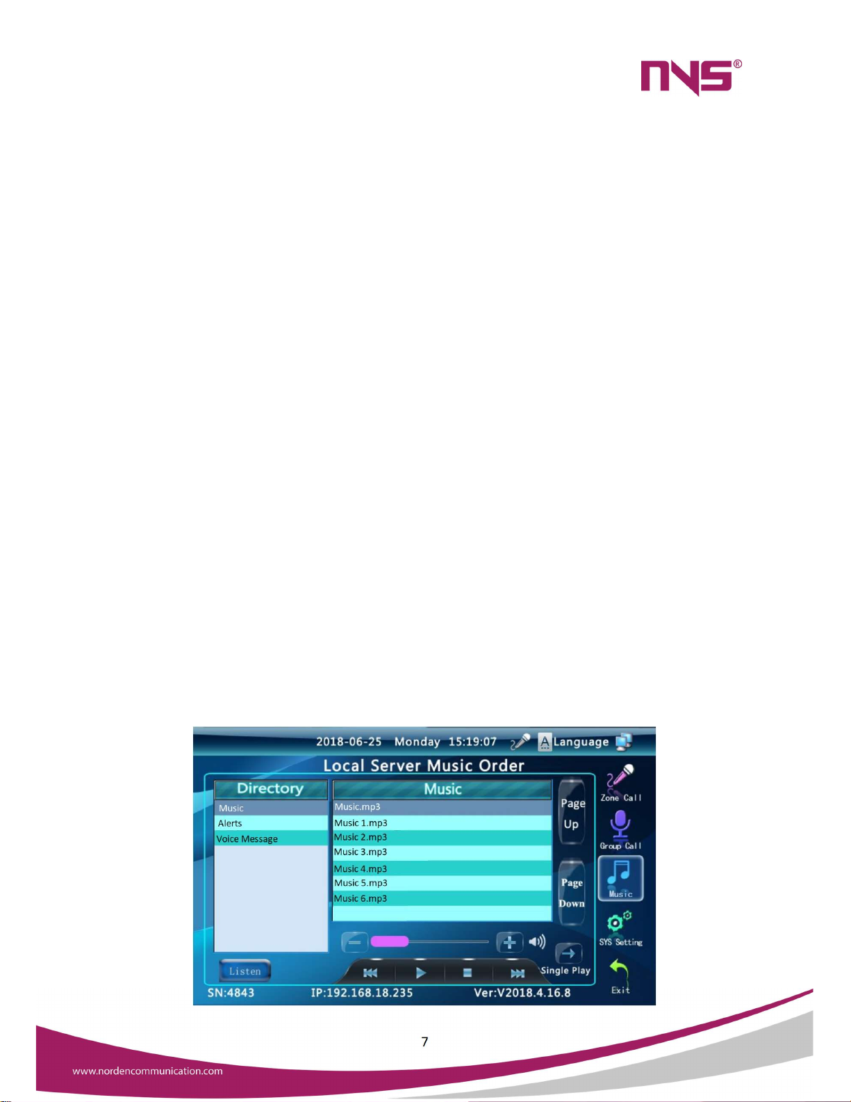
4.5 Pre-Listening Broadcast
There is an inbuilt speaker to pre-listen programs (Messages, Background music etc.) before broadcasting
it. To pre-listen, select “Music” button available on the right side of the screen. Then the following page
will appear.
8
The programs folders in the server will display under “Directory” area. Once a directory is selected, the
program files will be displayed under “Music” area. On the bottom left area, there is a toggle button. It will
toggle between “Listen” & “Broadcast”. This button should be in listen mode to pre-listen a music or
message. Then open the required directory & play the music. Music controls are given in the bottom side
of the menu.
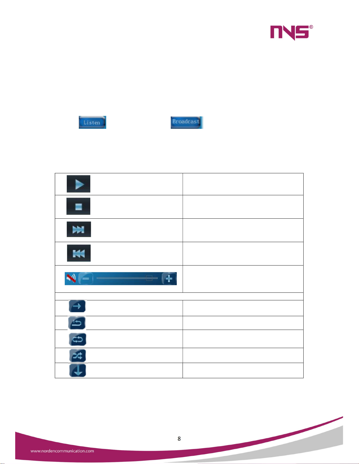
4.6 Zone Broadcast
Touch on button, & it will change to . The go to Zone call or Group call menu &
select the required Zones or groups. Then come back to music menu & play the required file.
The media control buttons are explained below:
Play button, to play the selected file
Stop playing music or message
Play next file
Play previous file
Volume control
Play Modes
Sequential playback
Repeat single file
Repeat all files in the directory
Play random files (Shuffle)
Stop playback after playing selected file
9
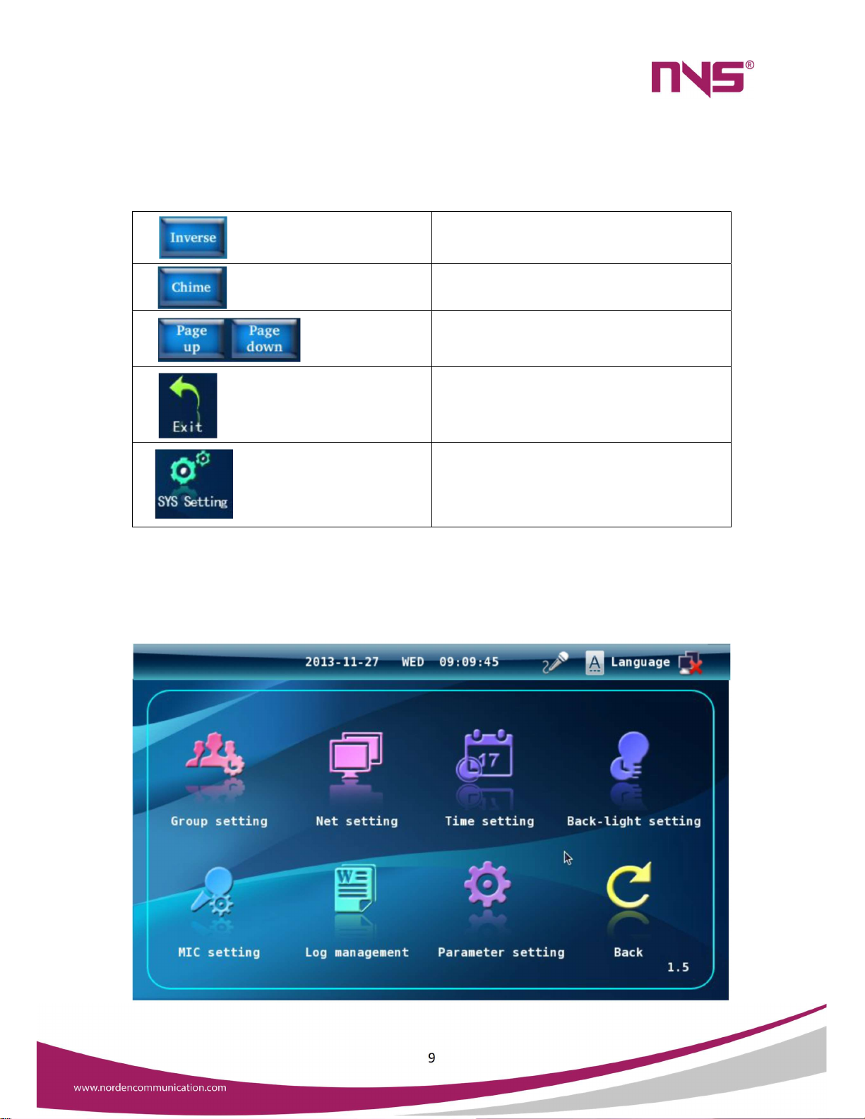
4.7 Other Buttons
Inverse the current selection
Play Chime tone
These buttons can be used for navigating to next
& previous page
Logout from main menu
Go to system settings
4.8 System setting
System settings can be opened by pressing “SYS Setting “Button.

10
The sub menu items are explained below:
Group settings : grouping settings for zones.
Network settings : Set IP address and subnet mask for this paging station.
Time setting : Set the system time and date.
Backlight time : For this paging station to set the screen backlight light time.
Microphone setting : Set the time of automatic shutdown of this paging station microphone.
Log management : View and monitor paging real-time recording log.
4.8.1 Group Setting
The following page will be displayed in the Group setting menu. The group names will be on the left side &
the Zones will be displayed in the right side. A new group can be created by pressing “Add” Button. The
name of the group can be edited by pressing the “Edit” button on the left side. A group can be deleted
using “Del” button.
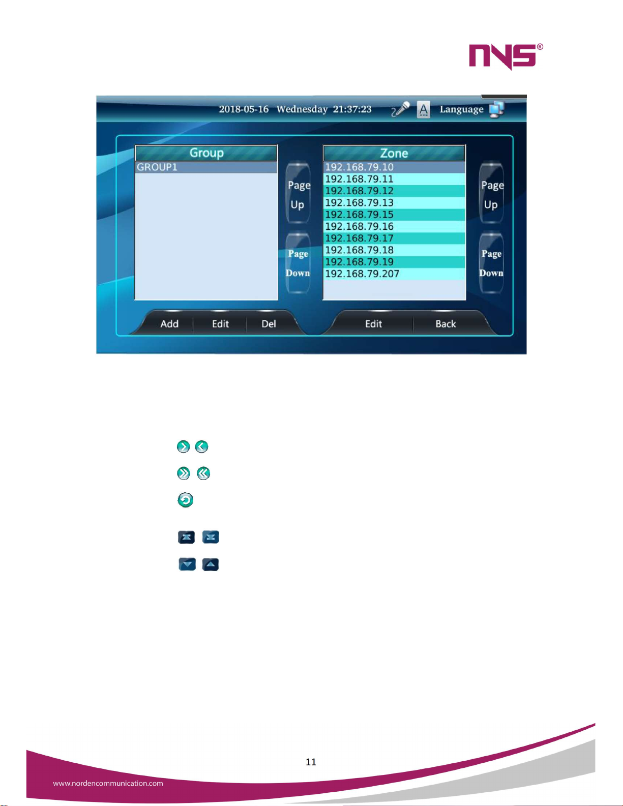
Once a group is created, the next step is adding zones to the group. For that, press “Edit” button on the
right side. Then the following page will appear.
11
Assign zones to the selected group on demand on the interface. The box on the right shows all the zones,
selects the zones you want to add to the current group, touches the arrows that point to the left border,
and moves to the left box to indicate that the group has been added.
In the interface to assign zones to a group:
The button can individually add or remove zones that are contained in a group.
The button to add or remove all zones in a group.
The button can be returned to the previous interface.
The button can switch the previous screen display and the next screen display.
The button can select the previous zone (or group) and the next zone (or group) of
the currently selected zone.

12
Group Add Zone Settings interface
When the group settings are complete, touch the "back" button to exit the Setup interface.
4.8.2 Network Setting
Enter the "System Settings" interface, touch the "Network Settings" icon, into the network settings of this
paging station interface. The IP address, subnet mask, gateway, and server IP of this paging station can be
set.
Click on the parameters that need to be modified, move the input cursor to the back of the
parameter, and then use the "Del" button in the input keyboard area to delete the original
number, then enter the target number by using the keyboard, or touch and move the finger, select
the parameter you want to modify, and then use the "Del" button in the input keyboard area, then
use the keyboard to enter the target number.
Click “OK” to confirm and exit the Setup interface when the settings are complete.
4.8.3 Time Setting
Enter the “system settings” interface and touch the “time setting” icon to enter the system time setup
interface. The current system time, date, is set on this interface.
When setting, touch the Gray triangle in the digital box to adjust the number.
After the completion of the touch of the "OK" button to confirm and exit the settings interface, if
not touch the "OK" button, but touch the "back" button to exit the settings interface, then the
setting operation will not change the time and date before.

13
4.8.4 Backlight Time
Enter the "System Settings" interface, touch the "Backlight time" icon to enter the screen backlight light
time Setup interface.
Touch the circle in front of the light time value or steady state, the circle inside the white display
"
√
" indicates selected. If you do not have any action on the pager in the selected time, the display
backlight will be automatically extinguished. It can play a role in energy saving and can prolong the
life of the display.
After the completion of the touch "OK" button to confirm the exit settings interface, or direct
touch "back" cancel this setting and exit the Setup interface.
4.8.5 Microphone Setting
Enter the “System Settings” interface and touch the “Microphone Settings” button to enter the
microphone automatic shutdown time setting interface.
Touch the circle in front of the time value or the open state, the white in the circle shows the
"
√
" sign selected. During the selected time, if the microphone has no signal input, the paging
microphone and the paging section will automatically close.
Touch the “OK” button to confirm and exit the Setup interface, or touch "return" to cancel this
setting and exit the Setup interface.
4.8.6 Log Management
Enter the “System Settings” interface and touch the "Log Management" button to enter the voice file
recorded during this paging action.
This paging station will record the paging action in real time and automatically back up the
recorded log files to the network host.
The audio files for paging are sorted by time and the last recording is at the front.
Recording log files can be monitored at this paging station.
Use the "X" button below the interface to remove the selected audio file from the log files list.
You can exit the log file management interface with button.

14
4.9 Parameter setting
Enter the "System Settings" interface, touch the "Parameter Settings" button to enter the parameter
settings interface, the interface as shown in the following image
Parameter Settings interface
4.9.1 Local Output Settings
Whether the line output (output) on the back panel of the machine is exported when the microphone or
line input is set. Touch the box in the front of "local output" to select the function: "√" sign in the box
indicates that the function is selected, that is, the output of the line output, there is no "√" in the box
indicates no output.
4.9.2 Screen Calibration
The touch screen may not move accurately to the operation item due to temperature increase after the
machine is used for a period, or the touch screen may be calibrated according to the following method.
Enter the "parameter setting" interface, touch the icon button in front of "screen calibration", and
start to calibrate the screen according to the prompts. Before entering the calibration screen, the
paging station system will be restarted, and the screen can be started after the start-up is
completed.
In the calibration screen interface, with the nib click on the small cross icon (black circle in the
picture) of the central position (note: certain points to the central location).
In the screen of the four corners and the central position of the above calibration, if not accurately
calibrated four corners and central position, then the selection of the cursor cannot be moved to
the action item.

15
Screen Calibration
Important NOTE:
Screen calibration operation should be carefully aligned to the cross cursor and then click, do not randomly
touch the screen, otherwise it is possible to make correction errors, resulting in the failure to operate. If
the touch screen cannot be used without accurate calibration screen operation, then the screen can be
reset by the "CALL ALL" button on the front panel of the paging station.
4.9.3 Set the System Login password
Set the password for the system login on the parameter settings interface. The interface is shown below.
16
In the figure above, use the number button on the right to enter the password. "Original password" set to
blank, if the user set their own password, the next time you change the password need to enter an existing
password to update the password. When the settings are complete, touch the “OK” button to take effect.
In the “System Setting” interface touch icon to exit the interface and returns to the main interface.
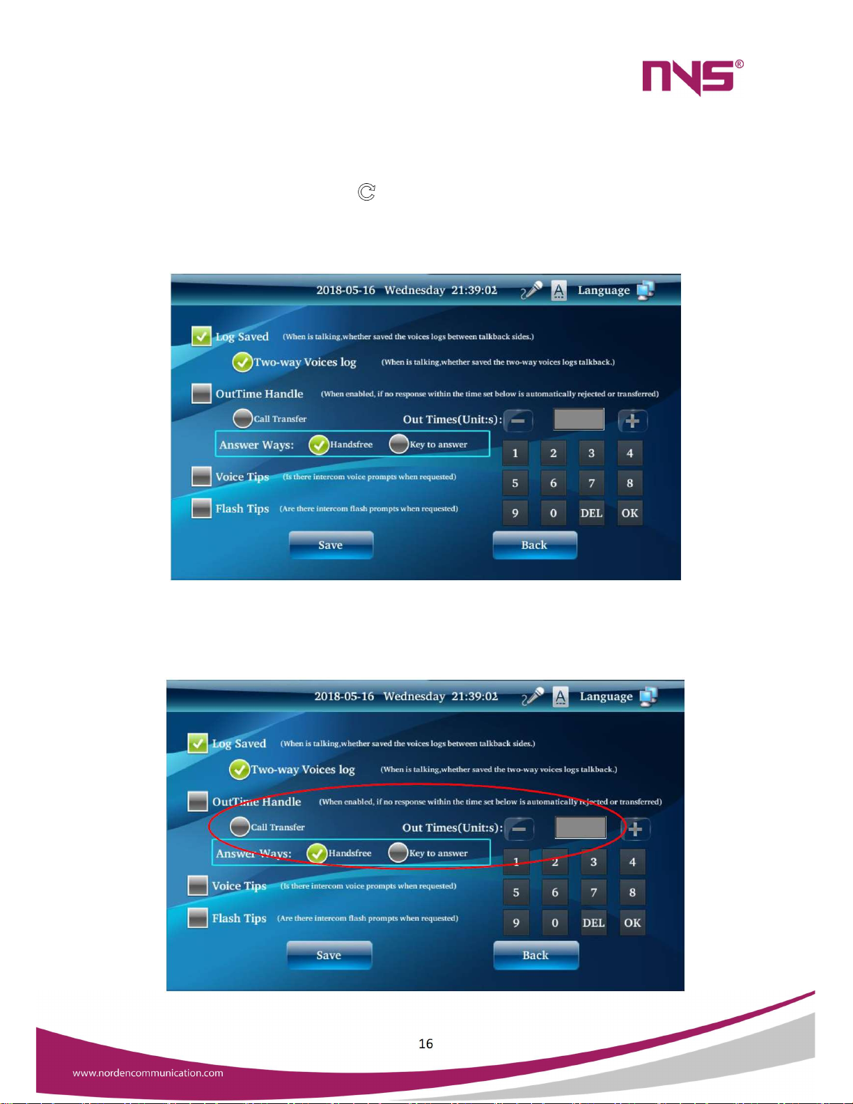
4.9.4 Set Intercom Parameters
Log Save options: Check the phone when you record the microphone said voice information.
Bi-directional voice preservation: Used to record voice messages on both sides of the intercom.
4.9.5 Timeout processing

17
Call Forwarding: Call the other party in the set time no answer, then automatically transferred to
the next intelligent paging station.
Timeout rejection: If the call transfer is not set to set the time to automatically refuse to speak
request.
Timeout setting: Use the figure keyboard input time and click OK Key to save.
Intercom tip : when there is a request to speak, prompts the user to access the intercom request.
Sound hint : Use the way of sound to prompt.
Flash Tip : Use flash method to prompt.
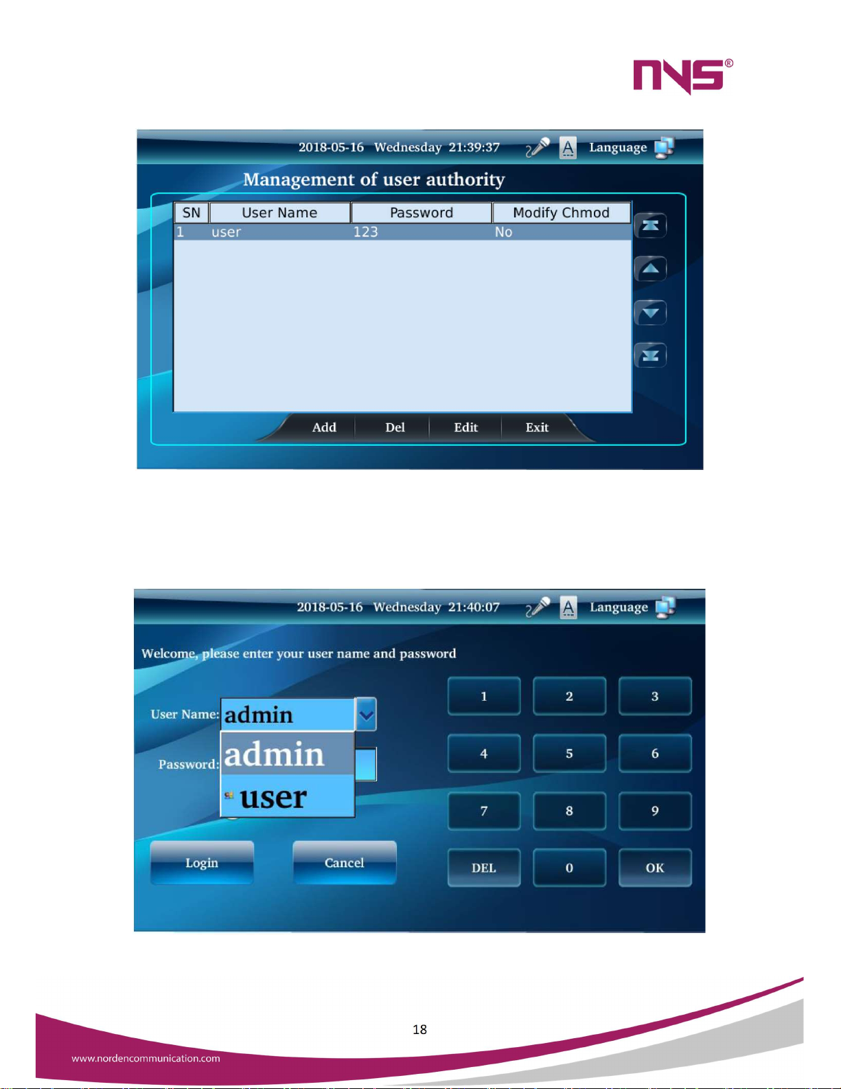
4.9.6 Set Multiple User Rights
Intelligent paging stations can be used by many people, different users can specify the zones they can see
and display, and they can specify whether the user has modified permissions for system parameters, which
are managed by the administrator.
System administrator users into the system settings, in the parameter settings interface click “User
Management” button, you can enter the user management interface to add, delete and modify operations,
the management of multiple user login password and modify permissions, the ordinary user's system
settings interface does not have "user management" button, the operating interface as shown in the
following figure
Click "Add" button to add new users and set their login password and modify the parameters of the
permissions.
As shown in the figure, if set three users, will be on the login page to display these user options, different
users can be based on their assigned password login system.
18
Different users can set the visible zones according to their actual requirements, administrators can assign
the user modify permissions, if not assigned permissions, the user enter the system settings can only set
the parameters such as backlight time, microphone settings, log, etc., and cannot set system parameters
such as grouping settings, zone management, network settings, such as parameters. If the click does not
have permission to prompt the following interface.
Multi-User Login Interface

19
Safety Precautions
Please do NOT connect this device to the power source before the system is correctly wired.
It is important to ensure that input voltage to the device is the same as required voltage of the
device, otherwise the device may be damaged.
There is dangerous voltage in the device, which may cause personal electric shock. Please do
NOT open the case without permission, to avoid potential risks of electric shock.
The device is not completely disconnected from power source when it is switched "OFF". For
sake of safety, please disconnect the device from the socket if it is not in use.
Please do NOT place the device where it is extremely cold or hot.
Good ventilation must be provided in the working environment of the device, to avoid excessive
temperature during its operation, which may cause damages to the device.
Please unplug the device from power socket in raining and wet days or if the device is not in use
for a long time.
Please disconnect the power plug from sockets, to ensure the device has been completely
disconnected from power source before any component is removed from or re-installed in the
device or before any electric connector of the device is disconnected or reconnected.
In case of any failure of the device, please do NOT open the case and repair without permission
from professional personnel, to avoid accident or additional damages to the device.
Please do NOT place any corrosive chemicals near or on the device.
Table of contents
Other Norden Microphone manuals


