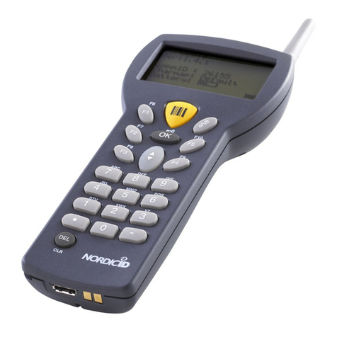
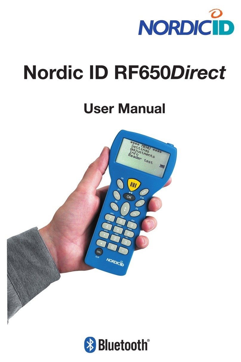
Nordic ID RF651 User manual

Nordic ID
RF651
®
USER MANUAL


Contents
Copyright 1
Disclaimer 1
Trademarks 1
Latest information 2
EU Declaration of Conformity 2
FCC Compliance Statement 2
FCC NOTICE 2
IC Related Information 2
Warranty and Safety Warnings 3
User Safety 5
Medical Equipment Compatibility 5
Care and Cleaning of the RF651 5
1. The System 6
1.1 Bluetooth 6
1.2 System Description 6
1.3 Principles of Operation 7
1.4 Operation of the Handheld Terminal 7
1.5 Security 8
2. RF651 Handheld Terminal 8
2.1 RF651 Main Features 8
2.2 Communication Requirements 9
2.3 Type Plate 9
2.4 Scanner 10

2.5 Laser Safety Label 10
2.6 Keyboard 11
2.7 Connectors 11
3. Using the RF651 12
3.1 First Time Activation 12
3.2 Connecting to the Access Server 12
3.2.1 Searching and Adding the Access Server(s) to the Device List 13
3.3 Using RF651 with the USB Bluetooth Adapter 14
3.4 Preparing the RF651 for connection without a Port Router 14
3.5 Preparing the RF651 for connection with a Port Router 14
3.6 Initial Display 15
3.6.1 Display Symbols 15
3.6.2 Status Messages 15
3.7 Function Keys 16
3.8 Input Fields 16
3.8.1 Filling Fields with the scanner 16
3.8.2 Locked Fields (Buttons) 17
3.8.4 Writing Letters 17
3.8.5 Removing Letters 17
3.8.7 Locking the Keyboard 17
3.9 Installing a demonstration environment 17
Preparing the Charger & RF651 18
Software Installation Procedure 18
4. Built-in Menu 20
4.1 Settings 20
4.1.1 Device List 20
4.1.2 PIN Code 21

4.1.3 Wait Connection 22
4.1.4 Channel 22
4.2 Adjustments 22
4.2.3 Volume 23
4.2.4 Battery Type 24
4.3 Information 24
4.4 Reader Test 24
5. Desktop Charger (DTC05) 24
5.1 General information 25
5.2 Equipment 25
5.3 Connectors 25
5.4 Indicators 25
5.5 Charging the Batteries 26
5.5.2 Audible Signals and the LED Indicator on the Charger 27
6. Application Development 27
7. Warranty, Support & Service 27
7.1 Warranty Coverage 27
7.2 Returning the Unit for Service 28
7.3 Extending the Normal Warranty 28
APPENDIX A - Troubleshooting 29
APPENDIX C - Introduction to the Linear Imager 30
APPENDIX D - Programming the Scan Engine 31
APPENDIX B - Introduction to the Laser Engine 33

© 2006 Nordic ID oy
RF651 User Manual Version 1 June 2006 1
Copyright
All rights to this manual are owned solely by Nordic ID. All rights reserved. Copying this manual without the written
permission from the manufacturer by printing, copying, recording or by any other means or the full or partial translation
of the manual to any other language including all programming languages using any electrical, mechanical, magnetic,
optical, manual or other methods or devices is forbidden.
Nordic ID reserves the right to change the technical specifications or functions of its products or to discontinue
manufacturing of any of its products without any written announcement and urges customers to ensure that the information
at their disposal is valid.
Disclaimer
Nordic ID products have not been designed, intended nor inspected to be used in any life support related applications
nor as a part of any other critical system and are not granted functional warranty if used in any such applications.
Some configurations of the RF651 contain a Class II laser device, which may cause injuries unless safety regulations
and instructions are observed. Nordic ID will not be held responsible for any injuries or damage resulting from use in
contradiction with the safety related instructions stated elsewhere within this manual or which are in contradiction to the
general safety Manual lines relating to Class II laser devices.
Nordic ID urges its customers to arrange proper and adequate user training, which includes safety issues for any personnel
using, programming or otherwise handling RF651 handheld terminals.
The sale, transfer and use of Nordic ID RF651 is subject to the Nordic ID General Conditions of Sale and the Nordic ID
End User License Agreement, in force at the time of purchase.
Trademarks
Nordic ID and the Nordic ID logo are all registered trademarks of Nordic ID Oy.
All terms mentioned in this User Manual that are known to be trademarks or service marks have been appropriately
marked in the list below with either the ©, ® or the ™ symbol. Nordic ID cannot attest to the accuracy of this information.
Use of a term in this User Manual should not be regarded as affecting the validity of any trademark or copyright.
Trademark Company / Owner of the Trademark
Bluetooth Bluetooth SIG (Special Interest Group)
Nordic ID
Nordic ID Oy
Nordic ID RF651
Nordic ID Port Router
Table: Identified trademarks used in this User Manual
Other trademarks are the property of their corresponding owners.

© 2006 Nordic ID oy
RF651 User Manual Version 1 June 2006
2
Latest information
For latest information on the RF651 and on possible changes to this manual please consult our web site at http://www.
nordicid.com.
EU Declaration of Conformity
Nordic ID declares, that the Nordic ID RF651 handheld terminal has been tested according to the standards EN 300 328-
2 and EN 301 489-17. The equipment conforms to the essential requirements of the Directive 1999/5/EC.
FCC Compliance Statement
This equipment has been tested and found to comply with the limits for a Class B digital device, pursuant to Part 15 of
FCC Rules.
These limits are designed to provide reasonable protection against harmful interference in a residential installation.
FCC NOTICE
• Use only the power cord and connector cables supplied by Nordic ID to connect the equipment and the power
supply.
• Use only shielded cables to connect I/O devices to this equipment.
• Changes or modifications not expressly approved by the party responsible for compliance could void the user’s
authority to operate the equipment.
The RF651 complies with FCC requirements. The FCC ID information is printed on the back side of the Handheld Terminal
under the laser caution label.
IC Related Information
This equipment complies with RSS-210 of Industry Canada.
Operation is subject to the following two conditions:
• The RF651 may not cause harmful interference, and
• The RF651 must accept any interference received, including interference that may cause
undesired operation.

© 2006 Nordic ID oy
RF651 User Manual Version 1 June 2006 3
Warranty and Safety Warnings
Please read these warranty and safety related warnings carefully before using the product.
Nordic ID RF651 is a radio device and should not be used in any environments where radio transmitting may cause
any harm. Typical but not limited to are the following types of environments: environments with explosive materials,
gases, demolition sites, hospitals, emergency care rooms, airplanes and areas with highly sensitive measurement
instrumentation.
Users with pacemakers are to be informed about the possible safety hazards posed by radio emitting devices. Placing
any radio emitting device near to a pacemakers is not recommended. Consult the pacemaker documentation for further
safety regulations and requirements set by the manufacturer of the pacemaker.
NOTICE: Persons using pacemakers should be aware that RF emissions from the RF651 may cause unwanted
interference if positioned too close to the pacemaker.
NOTICE: The RF651 has not been designed, intended nor inspected to be used in any life support related device
or system related function nor as a part of any other critical system and is granted no functional warranty if used
in any such applications.
The use of any radio emitting device in explosive environments and especially near explosives may pose serious threats.
Some models of the RF651 models contain a laser barcode reader. Users are advised to follow the general safety
procedures relating to the use of such laser devices.
The Nordic ID RF651 should not be used in critical systems where continuous operation is required and where the possible
loss of data or unwanted changes to data contents are not acceptable, such as in life support related systems.
Warranty will be void, if the product is used in any way which is in contradiction with the instructions given in this User
Manual, or if the housing of the Nordic ID RF651 has been opened or has been tampered.
The devices mentioned in this manual are to be used only according to the instructions described in this manual. Faultless
and safe operation of the devices can be guaranteed only if the transport, storage, operation and handling of the devices
are followed. This also applies to the maintenance of the products.
The RF651 contains no user serviceable parts inside the actual case apart from the batteries, which may be replaced if
required.
NOTICE: Use only AA-type alkaline or rechargeable batteries type: GB Batteries, Models GB 180AAHC, GP210AAHC
and GP230AAHC (GPI International). Do not mix batteries (do not use simultaneously batteries of different
capacity, brand, age or type). Observe correct polarity indicated on the label inside the battery compartment. Do
not attempt to recharge alkaline or other non-rechargeable battery types using the handheld terminal and the
desktop charger or any other charger. When charging batteries inside the terminal, use only Nordic ID charger
type DTC05.
NOTICE: With use of desktop charger use only applicable power supplies: JODEN ELECTRON Co., Ltd, Models:
JOD-4101-031, JOD-41B-029, JOD-41U-14A.
WARNING: The batteries must be discarded according to the local environmental laws and regulations. The
batteries may contain harmful, dangerous or lethal substances, and may cause injury or loss of life if handled
recklessly. Never dispose the batteries in a fire due to a risk of explosion.
Any repair of the Nordic ID RF651 must be done by an authorised service partner of Nordic ID.

© 2006 Nordic ID oy
RF651 User Manual Version 1 June 2006
4
WARNING: The Nordic ID RF651 handheld terminal, desktop charger and power supply contain no user serviceable
parts. Opening the cases will void the warranty and may cause injury. The handheld terminal contains batteries,
which may be changed by opening the battery cover.
Some configurations of the Nordic ID RF651 contain a Class II laser device which may cause eye injury if the beam is
directed straight or via a shining surface to the eye. The laser beam should never be pointed at the eye or eyes of people
or animals. Note that mirrors and reflecting surfaces may cause the beam to deflect in harmful ways. Never look directly
into the laser module when the beam is active.
In Accordance with
EN 60825-1 / A2:2001
(IEC 60825-1 Ed.1.2,2001-08)
650 nm laser
max. 1 mW output
ENGLISH SUOMI
LASER LIGHT VAARA LASERSATEILYÄ
DO NOT STARE INTO BEAM ÄLÄ TUIJOTA SÄTEESEEN
CLASS 2 LASER LUOKKA 2 LASER
DEUTSCH SVENSKA
LASERSTRAHLEN VARNING LASERSTÅLNING
NICHT DIREKTIN DEN LASERSTRAHL STIRRA EJ IN I STRÅLEN
SCHAUEN LASERPRODUKT DER KLASSE 2 KLASS 2 LASER
DANSK ITALIANO
LASERLYF LUCE LASER NON FISSARE
SE IKKE IND I STRÅLEN IL RAGGIO PRODOTTO
KLASSE 2 LASER AL LASER DI CLASSE 2
FRANÇAIS ESPAÑOL
LUMIERE LASER NE PAS LUZ LASER NO MIRE
REGARDER LE RAYON FIXEMENT FIJAMENTE EL HAZ
PRODUIT LASER DE CLASSE 2 PRODUCTO LASER DE LA CLASE 2
NEDERLANDS NORSK
LASERLICHT NIET IN LASERLYS IKKE STIRR
STRAAL STAREN INN I LYSSTRÅLEN
KLASSE-2 LASER LASER, KLASSE 2
PORTUGUÊS
LUZ DE LASER NÃO
FIXAR O RAIO LUMINOSO
PRODUTO LASER DA CLASSE 2

© 2006 Nordic ID oy
RF651 User Manual Version 1 June 2006 5
User Safety
CAUTION: Some configurations of the RF651 barcode scanner contain an integrated class II laser product.
Direct eye contact with the laser beam or with a reflected beam from a shiny surface may cause permanent damage to
the eyes. To avoid risks, please make sure that the following instructions are followed by anyone operating the RF651:
• Hold the Nordic ID RF651 at a slight angle about 10 – 30 cm (few inches) from the barcode label to be read. If the
surface of the barcode label is very reflective, scanning from directly above (90° angle) may cause reading errors.
NOTE: The actual reading distance depends on scanner configuration and/or size of the symbology.
• Push the <SCAN> button on the keypad while directing the beam so that the beam covers all of the bars on the label.
A beep or audio signal will be generated indicating that the scanner has successfully read the label. The scanner will
stay on or it will automatically turn off depending on the scanning options, which have been selected prior to activating
the scan function. During normal operation the beam will be switched off immediately after the barcode has been read
successfully.
Medical Equipment Compatibility
Medical devices, such as pacemakers, hearing aids, etc. are usually manufactured according to the IEC 601-1-2 standard.
This requires that devices must operate properly in an EM (Electromagnetic) field which has strength of 3V/m over a
frequency band from 26 to 1000 MHz. The RF651 Bluetooth radio module is transmitting at a frequency of 2.4 GHz. All
electric appliances may emit spurious RF signals at other than specified frequencies.
WARNING: Persons using pacemakers should be aware of the possible risk of interference from any electronic
device if positioned too close to the pacemaker.
Care and Cleaning of the Nordic ID RF651
The Nordic ID RF651 display window and the scanner window may be cleaned with a clean, non-abrasive, lint-free cloth.
Never use alcohol or detergents, as these may harm the materials of the casing or remove markings.

© 2006 Nordic ID oy
RF651 User Manual Version 1 June 2006
6
1. The System
1.1 Bluetooth
Bluetooth is an open specification for seamless wireless short-range communications of data and voice between both
mobile and stationary devices. For instance, the standard specifies how mobile phones, computers and PDAs interconnect
with each other and with computers or with office or home phones.
The first generation of the Bluetooth standard permits the exchange of data up to a rate of 1 Mbps per second, even
in areas with much electromagnetic disturbance. It transmits and receives via a short-range radio link using a globally
defined frequency band (2.4 GHz ISM band).
It has been specifically designed as a low cost and low power radio technology, which is particularly suited to short range
Personal Area Network (PAN) applications. It is the design focus on low cost, low size and low power which distinguishes
it from the IEEE 802.11 wireless LAN technology. For more information please see the Internet addresses www.bluetooth.
com and www.bluetooth.org.
1.2 System Description
The Nordic ID RF651 Wireless Data Collection System consists of three principal components:
• Nordic ID RF651 Hand Terminal
• USB Bluetooth adapter (Dongle) or Bluetooth Access Server(s)
• The application software running on the Host Computer
Fig. Using a RF651 with Bluetooth USB adapter Fig. Using a RF651 with Access Server.

© 2006 Nordic ID oy
RF651 User Manual Version 1 June 2006 7
1.3 Principles of Operation
The RF651 is a Hand Terminal equipped with a Bluetooth radio which allows connection with PC application software
through a USB Bluetooth adapter or Bluetooth Access Server. The USB Bluetooth adapter is packed in a Dongle which
is connected to any free USB port of the Host Computer (USB 1.1 or 2.0 compatible port). Bluetooth Access Servers are
connected to the Host Application using Local Area Network.
A Bluetooth connection will be established between the Hand Terminal and a USB Bluetooth adapter or an Access
Server. When the RF651 user sends data over the Bluetooth link, the USB adapter or the Access Server will pass the
data to the Host Application.
The user starts the transaction by using the Hand Terminal keyboard to make an entry, or by reading a barcode. The
Hand Terminal then sends this data to the Host Computer and waits for a message from the Host Application. If the Hand
Terminal does not receive a correct (check summed) message within the specified time-out period, it will resend the
original data as many times (retries) as it has been configured to do.
Note: When no entry is made on the Hand Terminal by the user, it will remain in a standby state and will not be able to
receive data from the Host Computer.
1.4 Operation of the Handheld Terminal
The RF651 Hand Terminal is designed to use application specific forms i.e. fields in the virtual display. This helps to make
the user interface of the Hand Terminal flexible and easy-to-use. The commands used to generate, modify, read and write
the forms are described in a document called “RF-series system developer guide”.
When no forms are used, the initial screen of the Hand Terminal shows as a prompt a user writeable header and an input
field. This field can be filled with data from the keyboard or from the scanner. Any text sent by the Host Computer will
clear the screen and show the text that was sent to the Hand Terminal. Any user input (from the keyboard or the scanner)
will clear the text and the initial screen will be displayed again.
The user of the RF651 Hand Terminal activates the connection between the RF651 and the USB Bluetooth adapter or
the Access Server. Available Bluetooth devices can be searched from within the coverage area of the Hand Terminal
Bluetooth radio and the discovered Bluetooth devices answering the search can be saved onto a device list contained in
the memory of the Hand Terminal. The user can then proceed to create the actual connection with the selected device.
It is also possible to have the Hand Terminal wait for a connection from a Bluetooth USB Dongle. If a Bluetooth dongle
is used, it is recommended to use the Nordic ID PortRouter –software to managing and maintaining the connections to
the backend software.
Each Bluetooth device (USB Bluetooth adapter) has a unique Bluetooth Address (BT_ADDR) and a “Friendly Name”.
Usually the Host Computer name is used as the “Friendly Name”. When the Nordic ID RF651 Hand Terminal searches for
Bluetooth devices, the user will see a list which will display the “Friendly Name” of all discovered Bluetooth devices. The
user can select from the list, in which device the Hand Terminal is trying to connect.
Fig. Device list screen on the RF651

© 2006 Nordic ID oy
RF651 User Manual Version 1 June 2006
8
After Reset, power-up or after changing the batteries, the Nordic ID RF651 will try to connect to the last device, in which
it was connected before switching off the power. If this device is not found, the device list (“Friendly Name”) will appear
on the screen and the user can select another device to connect.
Connection will be maintained until the Nordic ID RF651 goes to sleep, which will happen if no keys are pressed within
90 seconds, or alternatively the RF651 will maintain the connection also during the sleep (only display will be switched
to sleep mode). The user may select the type of operation by a special keyboard combination command (<SHIFT> +
<1> will toggle between the two different operation modes). When the user wakes the device up by pressing any key, the
Bluetooth connection will be established again if it was disconnected during entry into sleep mode.
1.5 Security
Bluetooth technology offers a high level of data transfer security. It is necessary that no external party without proper
authentication is able to access the network with a Bluetooth capable device.
Security implementation on the Nordic ID RF651 system is based on three factors:
• PIN code (0000-9999). The PIN code defines the Nordic ID RF651 network. The PIN code must be the same in the
Bluetooth Dongle installed into the Host Computer or on the Bluetooth Access Server(s) and in the Hand Terminal
before they can communicate with each other.
• Bluetooth data link encryption
• Authorizing scheme at the application side
This may include a password and user name input screen defined by the Host Application and displayed as the first
screen visible to the user trying to connect to the Host Application. Thus even with an authorized Bluetooth Hand
Terminal the user will have to identify him/herself. Furthermore the CommID of the Hand Terminal may also be used to
distinguish between an allowed and rejected Hand Terminal.
2. The Nordic ID RF651 Handheld Terminal
2.1 The Nordic ID RF651 Main Features
• Fast transactions with the Host Application over a Bluetooth connection (approximately 200 ms).
• Connects automatically to the last connected device after reset.
• Class 1 RF output power (100 meters).
The Nordic ID RF651 Hand Terminal is like a “Remote control” of the Host Application. No programming
is required in the Hand Terminal and the displayed screens (text) are defined by the Host Application. The
Host Application defines the user interface elements of the Hand Terminal screens.

© 2006 Nordic ID oy
RF651 User Manual Version 1 June 2006 9
User interface (UI) elements are:
• Text strings
• Input fields
• Buttons
• Pop Messages
Label includes the following information:
• Type of the Hand Terminal
• Serial number of the Hand Terminal
• CommID (a communications identification number,
which can be used by the Host Application to identify
a particular Hand Terminal)
• Configuration code
Please note that there might be several types of Hand Terminals with different configuration. For further details please
contact Nordic ID or your local reseller.
The CommID (Communication ID) is a fixed number, which is used to identify transmissions. In RF6XX system this
number was the same as the serial number of the device. CommID range is 0 - 65535.
Using these UI elements it is possible to build flexible user interfaces, which are used to control and input data or read
data to and from the Host Application.
2.2 Communication Requirements
The RF651 Hand Terminal can communicate with a Host Application when all of the following requirements are met:
• When using the Bluetooth Dongle: The Bluetooth Dongle is connected to the Host Computer’s USB-port and the
Bluetooth driver and software are installed and configured properly.
• When using an Access Server(s): The Access Server(s) is connected to the LAN and is installed and configured
properly.
• A Bluetooth radio connection has been established between the Dongle or Access Server(s) and the Hand
Terminal.
• Host application connection to the USB Dongle or the Access Server(s).
2.3 Type Plate
This label is located inside the Hand Terminal battery compartment and may be read by removing the battery compartment
cover and the batteries. The type plate also contains markings to indicate the correct orientation and polarity of the
batteries or re-chargeable batteries.
Fig. RF651 User Interface elements in display.
Fig. Type plate of the RF651.

© 2006 Nordic ID oy
RF651 User Manual Version 1 June 2006
10
2.4 Scanner
The Nordic ID RF651 can be equipped with two types of scanners; the laser scanner and the linear imager. The main
difference between these two technologies is that the laser scanner uses the laser light to encode the symbology. The
laser scanner can decode the most common barcodes used.
Both scanners can be configured to encode only certain types/lengths of barcodes. The configuration manuals are
available from Nordic ID by request.
Note: The scanner will not always be activated upon pressing the <SCAN> button. The activation of the scanner is also
controlled by the currently active input field (allow reader activation / do not allow reader activation).
The linear Imager uses the imaging technology to encode the symbology. The linear imager encodes the most common
barcode types and stacked codes.
The status message below is visible when the laser reader module is activated by pressing the yellow <SCAN> button.
2.5 Laser Safety Label
In some configurations the RF650 Hand Terminals contain
a Class II laser device. The required caution label is located
at the back side of the Hand Terminal.
Fig. RF651 equipped with Laser scanner Fig. RF651 equipped with Linear imager
Fig. Laser safety label at backside of the RF651

© 2006 Nordic ID oy
RF651 User Manual Version 1 June 2006 11
2.6 Keyboard
RF600 has 22 button keyboard; scan-key, 5 programmable function keys F1-F5, OK, shift and Up-Down movement –key,
12 alpha/numeric keys and a DEL-key.
Scan -key
Function -keys (F1 - F5)
Alpha / numeric -keys
Del -key
Up / down -movement key /
charging indicator
OK -key
2.7 Connectors
The connectors are located at the bottom of the RF651.
Charging -connectors
I/O -connector
Fig. The keyboard of the RF651
Fig. Connectors of the RF651

© 2006 Nordic ID oy
RF651 User Manual Version 1 June 2006
12
3. Using the RF651
3.1 First Time Activation
After inserting batteries (2 x AA 1,5 V alkaline or NiMH batteries – note that alkaline batteries may not be charged)
to the Hand Terminal for the first time, the device starts to search the Bluetooth network. The hand terminal must be
configured to Bluetooth network from the internal menu by pressing the <shift>+<0> The following Settings screen will
be displayed:
• Device list Access Servers defined as a part of the system.
• Search Activate the search for nearby Bluetooth devices,
• PIN Code 4-digit PIN code setting
• Wait Connection Waits for a Bluetooth connection from another device.
• RF-settings Bluetooth channel, resending times, reception timelimit and “what” behaviour -settings.
The RF651 needs to be set up for the Bluetooth connection with the USB adapter or the Access Server.
Use the up/down -keys to highlight a specific item from the list and press <OK> key to select it.
3.2 Connecting to the Access Server
This section describes how to create the Bluetooth connection with the Access Server. It is assumed that all configurations
and settings are already made in the Access Server and the Host Application side (for further information see Access
Server related documentation).
The WRAP Access Server support up to 7 or 21 connections simultaneously. The RF651 can be connected to one
Access Server at time, but with the roaming capability the hand terminal use area can be expanded just adding another
Access Server to the LAN.
Fig. Operation diagram of the RF651 and WRAP servers
Fig. Settings menu of the RF651

© 2006 Nordic ID oy
RF651 User Manual Version 1 June 2006 13
In order to connect to the Access Server, the following requirements must be fulfilled:
• PIN Code: Default PIN code in Hand Terminals is “1234”. The PIN code must be the same in the Hand Terminal and
in the Access Server(s) before they can connect to each other. For security reasons, it is recommended to change the
PIN code to something differing from the often used “0000” or “1234”.
• Channel: The Hand Terminal user creates the connection to the Access Server. In order to allow several Hand Terminal
connections simultaneously with an Access Server, Hand Terminals must use the same channel. Channel numbers can
be between 5 and 31.
• Access server: Must be properly configured.
3.2.1 Searching and Adding the Access Server(s) to the Device List
Before a Hand Terminal can connect to the Access Server, the Bluetooth address of the Access Server must be known.
Inquiring Access Servers within the coverage area of the Hand Terminal:
Select <Search> and press the <OK> button in order to start the inquiry process. Inquiry will take approximately 10 - 20
seconds.
Bluetooth radio module inside the Hand Terminal will now search ALL available Bluetooth devices within the coverage
area. Note that unwanted Bluetooth devices might also be found and listed. If the area contains a lot of detectable
Bluetooth devices, the RF651 can be configured to find only the Access Server -type of Bluetooth device.
When the desired Access Server is found, select it and save it to the device list. The search procedure may need to be
activated several times before the desired Access Server is detected.
Save all desired Access Servers to be included in the system by selecting <Save> and pressing <OK>.
The user can also add Access Servers manually to the Device list by editing Name: and Addr: fields. In this case the
Bluetooth address of the Access Server must be known.
Fig. Connecting to the device
Fig. Devices found menu of the RF651

© 2006 Nordic ID oy
RF651 User Manual Version 1 June 2006
14
In order to create a connection with the selected Access Server, the user must select the Access Server from the “Device
list”. After selecting the <Connect> choice and pressing the <OK> button, the Hand Terminal will try to establish a
connection with the Access Server. This typically takes approximately 5 seconds.
While connecting, the message below will be displayed:
Status message appears in bottom of the display while connecting.
If the connection cannot be established with the Access Server, try again by selecting <Connect> and pressing the
<OK> button.
After successful connection, the Hand Terminal is ready for communicating with the Host Application. Initial screen
appears and the user can start to use the Host Application by pressing <OK> or any <F> key for sending data to the Host
Application for the first time. Usually the Host Application returns a user interface screen for using the actual business
application. If batteries are taken off and placed back again, the Hand Terminal resets first and then connects to the latest
connected device automatically.
3.3 Using RF651 with the USB Bluetooth Adapter
This section describes how to create the Bluetooth connection with the USB adapter (Dongle). It is assumed that all
configurations and settings are already made on the Dongle and Host Application side.
The RF651 Hand Terminal (HT) can communicate via a Bluetooth USB adapter (Dongle). In order to use more than one
RF651 device via a single Dongle, the Nordic ID Port Router software must be used.
The Nordic ID Port Router software allows a maximum of seven simultaneous Bluetooth connections via single Dongle.
If not using Port Router, only one RF651 Hand Terminal at a time can be used with the Dongle.
3.4 Preparing the RF651 for connection without a Port Router
• Set Channel to 0
• Set proper PIN code
• Search and add Dongle Name (PC name) and Bluetooth address to the device list.
• Choose Dongle from the device list for connection, select <Connect> and press <OK>.
3.5 Preparing the RF651 for connection with a Port Router
• Set Channel 5
• Set proper PIN code
• Select <Wait connection>, press <OK> and establish a connection from PortRouter.
(see Port Router manual for detailed information)
Fig. Initial screen of the RF651 when the device is connected

© 2006 Nordic ID oy
RF651 User Manual Version 1 June 2006 15
3.6 Initial Display
The Initial screen will appear when a Bluetooth link between the Norcid ID RF651 Hand Terminal and an Access Server
or a Dongle has been established.
The user can start to communicate with the Host Application. Connection to the Host Application is started by pressing
the <OK> button or any <F> key.
The Initial display screen will always appear in the display if no fields are defined in Host Application. This is usually the
case when the Hand Terminal is activated after a reset and the Bluetooth connection has been established.
The Initial display includes a header, the text of which can be defined by the user, and an input field (max. length 18
characters). The user may input a text string or read a barcode by pressing the <SCAN> button and then send the data
to the Host Application by pressing the <OK> button.
Actual display (form) size is 12 rows with 20 characters per row. The visible area is always 8 rows with 4 rows not visible.
These “virtual rows” may be scrolled on to the screen by pressing the up/down -key accordingly.
When sending first time data from the Initial screen to the Host Application , the Host Application returns in the Main
Menu of in the Host Application Server or Workstation running business application.
3.6.1 Display Symbols
Sometimes the following symbols are shown on the right side of the display:
SHIFTLOCK
This symbol indicates the status of the <SHIFTLOCK> key. The status can be changed by pressing the
<SHIFT> key. When visible, the shift function of the keyboard is active, making it possible to enter letters
instead of numbers.
TRANSACTION
This sign shows up, when the Hand Terminal is communicating with the HOST. When the Host Application
is processing data the user has to wait for the answer and the flash sign will appear on the lower right corner
of the display. The user must wait for an answer from the Host Application. The default waiting time setting is
3 seconds.
3.6.2 Status Messages
Status messages are shown in the bottom of the display. The complete row of text is highlighted, which will show as
white text on black background. Status messages appear and disappear automatically.
The Hand Terminal is searching for the Bluetooth devices. The Hand Terminal tries to find the devices for approximately
20 - 30 seconds.
The RF651 will try to connect to the selected Bluetooth device (Access Server).
Bluetooth connection is established and the user can start to use the Host Application.
If no answer from the Host Application is received within the specified time, the above message will appear on the
status line and three error beeps will also be generated. This situation arises usually when the Host Application is being
maintained or the server is down or the LAN network connections are broken.
Table of contents
Other Nordic ID Barcode Reader manuals
Popular Barcode Reader manuals by other brands
Symbol
Symbol LS1902-T Programming manual
Motorola
Motorola SYMBOL DS3578 Product reference guide
Symbol
Symbol LS 3020 Special operating instructions
Banner
Banner ABR 3000 series quick start guide
Psion
Psion PowerScan M8300 series Quick reference guide
Hand Held Products
Hand Held Products HandHeld 3800 Linear Series quick start guide
