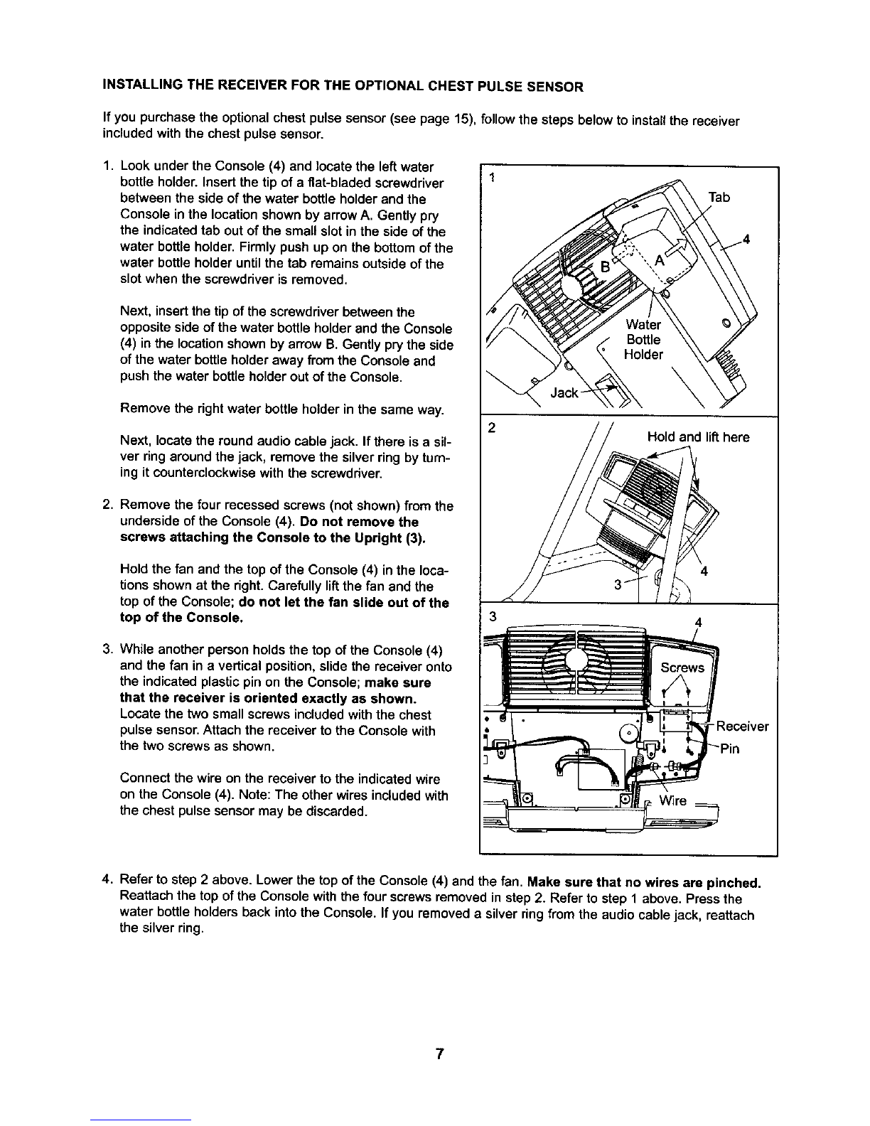
HOW TO USETHE MANUAL MODE
B Begin stepping to activate the console.
The stepper requires no batteries or external
power source. Power is supplied to the step-
per by a generator while you are stepping, To
activatethe console, begin stepping.After a few
seconds, the console displayswilllight,A tone
willthen sound and the consolewill be ready for
use.
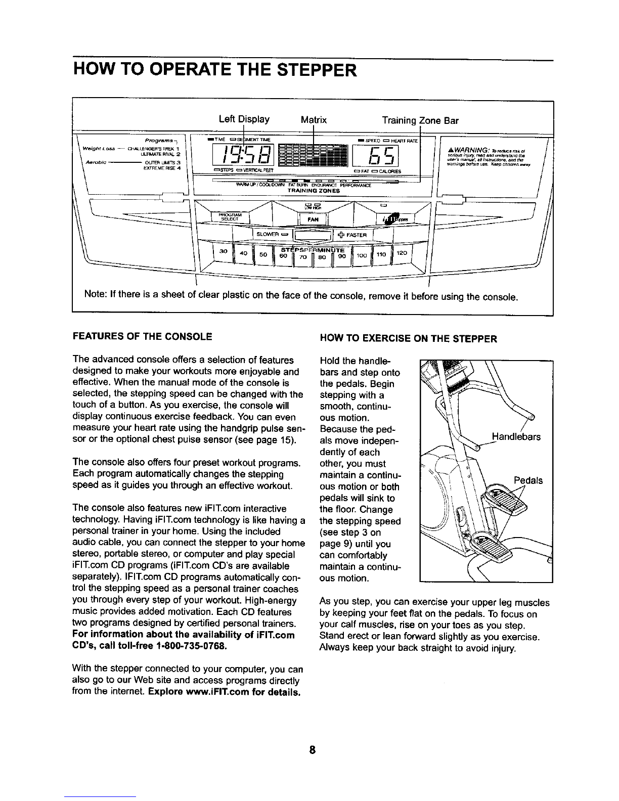
Select the manual mode.
When the power is
turnedon, the
manual mode will
be selected. Ifyou
have selected a
programor the
iFIT.com mode,
select the manual mode by pressing the Program
Select button repeatedly until a staircase appears
in the matrix and the indicator above the iFIT.com
button is not lit.
B Begin stepping and change the stepping
speed as desired.
While you are Ill _PEED _ HEART RATE
stepping, change [ }
the stepping .C _,_
speed by pressing _--I -_
the Slower or ==FAT==CALC_ES
Faster button.
When the Slower
button is pressed, the resistance of the pedals
will increase and your stepping speed will
decrease; when the Faster button is pressed, the
resistance will decrease and you will have to
increase your steppingspeed to prevent both
pedals from sinkingto the floor. The stepping
speed can be decreased or increased in incre-
ments of 5 steps per minute. To change the step-
ping speed quickly, press one of the Steps Per
Minute buttons.
Note: After the Slower, Faster, or Steps Per
Minute buttons are pressed, it will take a moment
for the stepper to reach the selected setting.
Make sure to continue stepping while changing
the stepping speed.
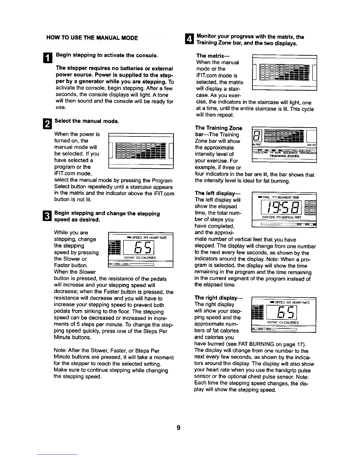
B Monitor your progress with the matrix, the
Training Zone bar,and the two displays.
The matrix--
When the manual
mode or the
iFIT.commode is
selected, the matrix
will display a stair-
case. As you exer-
cise, the indicators in the staircase will light, one
at a time, until the entire staircase is tit.This cycle
will then repeat.
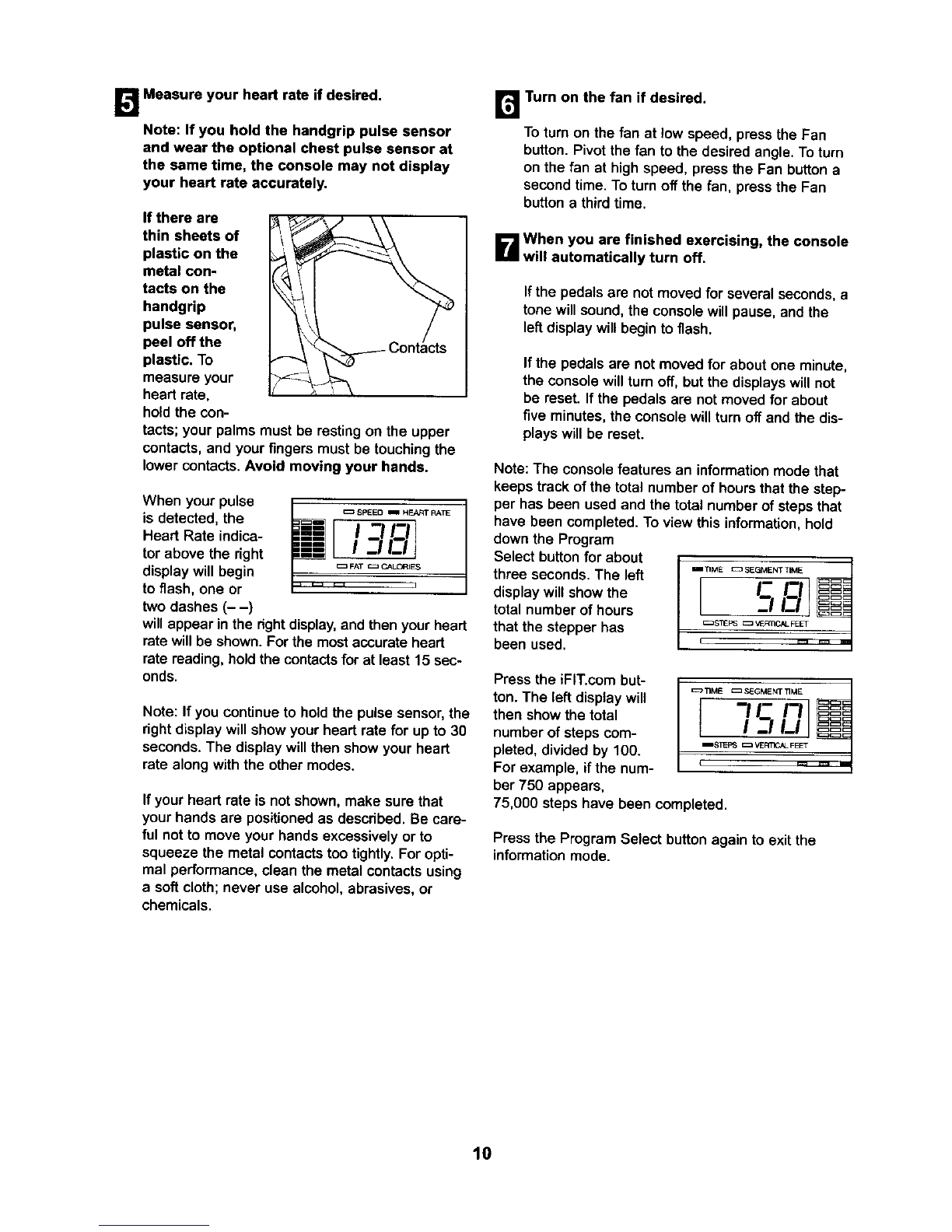
The Training Zone
bar--The Training
Zone bar willshow
the approximate
intensity level of
your exercise. For
example, if three or
four indicators in the bar ere lit, the bar shows that
the intensity level is ideal for fat burning.
The left display-- .-_ME=:::=SEGMENTTIME
The left display will /
show the elapsed L
time, the total num- == S_PS c= VE_ FEET
ber of steps you
have completed,
and the approxi-
mate number of vertical feet that you have
stepped. The displaywiltchangefrom one number
to the next every few seconds, as shown by the
indicators around the display. Note: When a pro-
gram is selected, the display will show the time
remaining in the program and the time remaining
in the current segment of the program instead of
the elapsed time.
The right display--
The right display
willshow yourstep-
pingspeed and the
approximatenum-
bers offat calories
and calodesyou
mm SPEE Dc_ HEART RATE
I-I-
k-zu ;
I
have burned (see FAT BURNING on page 17).
The display will change from one number to the
next every few seconds, as shown by the indica-
tors aroundthe display. The display will also show
your heart rate when you use the hsndgrip pulse
sensor or the optional chest pulse sensor. Note:
Each time the stepping speed changes, the dis-
play will show the stepping speed.
9