Nordisk Teltbutikk SST304716 User manual

Page 1
Double Truss Shelter
Model# SST304716
W9.14xL14.2xH4.88m
Assembly Instructions

Page 2
RECOMMENDED TOOLS
Equipment List
Speed Wrench
22#.23#.24#
Hammer (30lb)
Rope (12#)
Long Tape (50m)
Hammer Drill*1
Lifter*2
Crane*1
Forklift*1
Protective
equipment

Page 3
YOU MUST READ THIS DOCUMENT BEFORE YOU BEGIN TO ASSEMBLE THE SHELTER.
Thank you for purchasing our shelter. When properly assembled and maintained, this product will
provide years of reliable service. These instructions include helpful hints and important information
needed to safely assemble and properly maintain the shelter. Please read these instructions before you
begin.
If you have any questions during the assembly, please contact local dealer for assistance.
SAFETY PRECAUTIONS
. Wear eye protection.
. Wear head protection
. Wear gloves when handling metal tubes
. Use a portable GFCI (Ground Fault Circuit Interrupter) when working with power tools and cords.
. Do not climb on the shelter or framing during or after construction.
. Do not occupy the shelter during high winds, tornadoes, or hurricanes.
. Provide adequate ventilation if the structure is enclosed.
. Do not store hazardous materials in the shelter.
. Provide proper ingress and egress to prevent entrapment.
ANCHORING INSTRUCTIONS
Prior to assembling this shelter, please read the MUST READ document included with the shipment.
WARNING: The anchor assembly is an integral part of the shelter construction. Improper anchoring
may cause shelter instability and failure of the structure. Failing to anchor the shelter properly will void
the manufacturer’s warranty and may cause serious injury and damage.
LOCATION
Choosing the proper location is an important step before you begin to assemble the structure.
The following suggestions and precautions will help you determine whether your selected location is the
best location.
. Never erect the structure under power lines.
. Identify whether underground cables and pipes are present before preparing the site or anchoring the
structure.
. Location should be away from structures that could cause snow to drift on or around the building
. Do not position the shelter where large loads such as snow and ice, large tree branches, or other
overhead obstacles could fall.
SITE
After choosing a location, proper preparation of the site is essential. The following site characteristics will
help ensure the integrity of the structure.
. The support structure must be level to properly and safely erect and anchor the frame.
. Drainage: Water draining off the structure and from areas surrounding the site should drain away from
the site to prevent damage to the site, the structure, and contents of the structure.
WARNING: The individuals assembling this structure are responsible for designing and furnishing all
temporary bracing, shoring and support needed during the assembly process. For safety reasons, those
who are not familiar with recognized construction methods and techniques must seek the help of a
qualified contractor.
Page 4
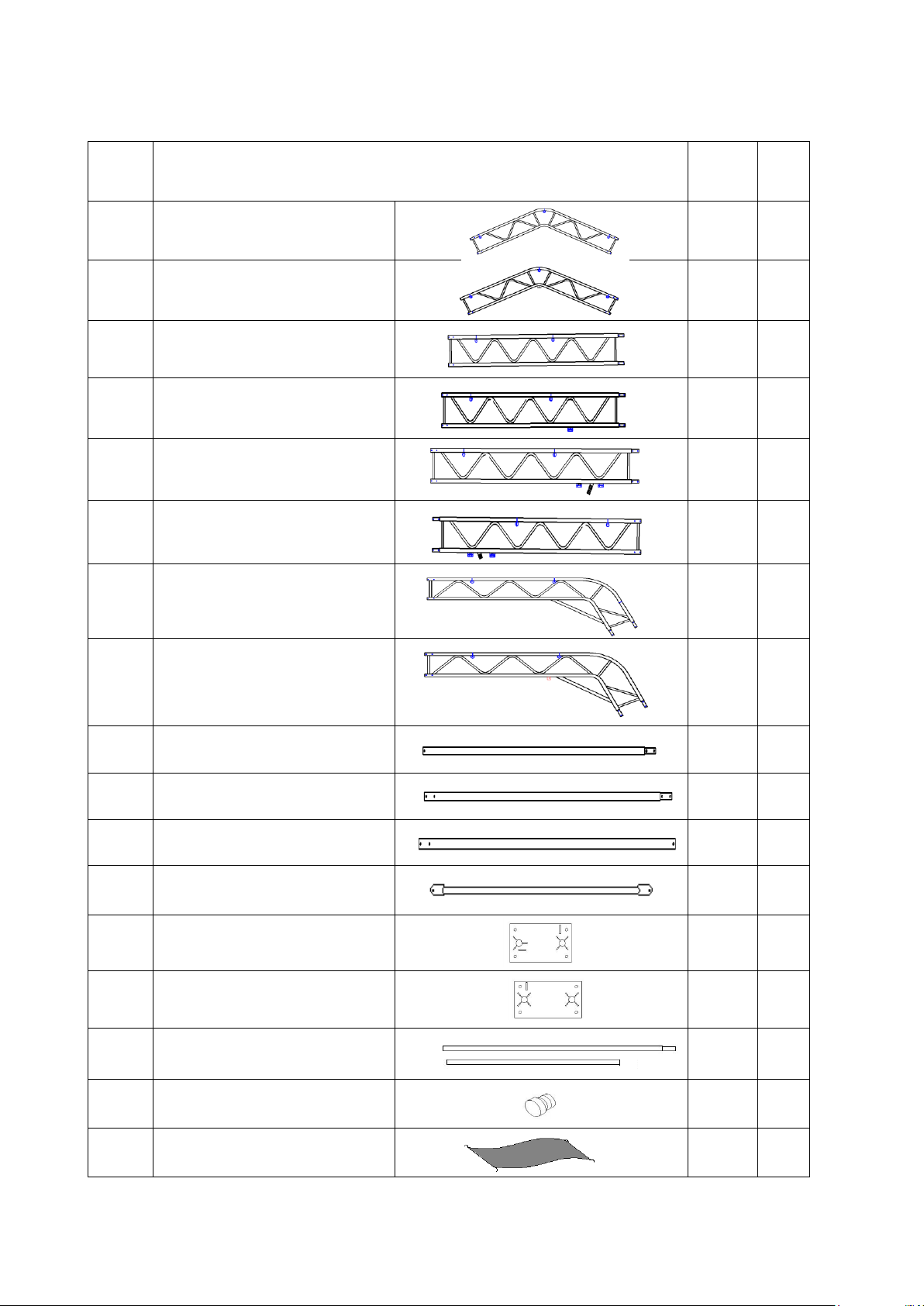
Double Truss Shelter W9.14xL14.2xH4.88m Parts List
Part
Code
Description
Qty/
PCS
Box
1
Top Truss Arch for middle
6
A
1A
Top Truss Arch for front and
back end (with connection plate)
2
A
2
Upper Truss Arch for middle
12
A
2B
Upper Truss Arch for front end
2
A
2A
Upper Truss Arch for back
end-left
1
A
2C
Upper Truss Arch for back
end-right
1
A
3
Shoulder Bent Truss Arch for
middle
12
A
3A
Shoulder Bent Truss Arch for
front and back end (with
connection plate)
4
A
4
Purlin (between Arch No.1 & 2)
11
B
4A
Purlin (between Arch No.2 to 6)
55
B
4B
Purlin (between Arch No.6 & 7)
11
B
5
Bracing Tube
12
B
6
Base Plate for four corners
4
A
7
Base Plate for middle
12
A
8
Tensioning Tube for Roof Cover
(5pcs/set)
2 sets
B
8A
Plastic Plug for tensioning tube
No.8
4
B
9
Roof Cover
1
B
Page 5
10
Tube Clip for bracing tube No.5
24
B
11
Bolt M10x50 for tube clip No.10
24+2
B
12
Bolt M8x60 for swaged tube of
truss arch
192+5
B
13
Bolt M8x100 for purlins
88+5
B
13A
Bolt M8x50 for purlin No.4, 4A,
4B
66+5
B
14
Winch for tensioning tube No.8
20
B
15
Knitting Rope for Roof Cover
1
bundle
A
16
Cable Tie for Roof Cover
70
A
17
Belt for winch No.14
16
A
18
Stake Peg (normal conditions)
48
A
18A
Earth Auger with its tool (normal
conditions)
16
A
18B
Expansion Bolt (concrete
ground)
64
B
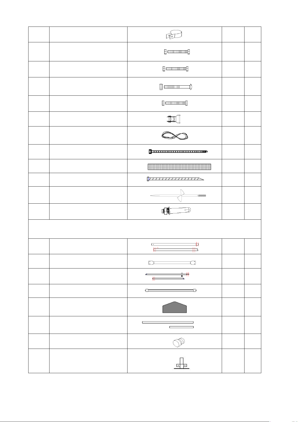
Back End Panel
19
Portal for back end (2pcs/set)
2 sets
B
20
Short Vertical Bar for back end
1
B
21
Door Cross Beam for back end
(2pcs/set)
1 set
B
22
Rail for back end
4
B
23
Back Cover
1
B
23A
Tube in door cover (2pcs/set)
1 set
B
23B
Plastic Plug
2
B
24
Base Plate for back end
2
A

Page 6
25
Bolt M8x50 for swaged tube
10+2
B
26
Bolt M10x30 for connection plate
20+3
B
27
Cable Tie for Back Cover
65
A
28
Knitting Rope for Back Cover
1
bundle
A
29
Stake Peg (normal conditions)
6
A
29A
Earth Auger with its tool (normal
conditions)
2
A
29B
Expansion Bolt (concrete
ground)
8
B
Front End Panel
30
Portal for front end-right
(2pcs/set)
1 set
A
30A
Portal for front end-left (2pcs/set)
1 set
A
31
Portal for front end
1
A
32
Rail for front end (2pcs/set)
1 set
B
33
Rail for front end
4
B
34
Front Cover with door cover
1
B
35
Door Bolt
2
B
36
Connection Plate for portal
No.30 & 30A
4
A
37
Winch with bolt for front door
1 set
A
38
Tube in door cover (2pcs/set)
6 sets
B
39
Bolt M8x120 for square tube
connection
8
B
40
Bolt M10x30 for connection plate
18+3
B
40A
Bolt M8x70 for curved plate
2
B

Page 7
41
Knitting Rope for front cover
1
bundle
A
42
Cable Tie for front cover
90
A
43
Stake Peg (normal conditions)
6
A
43A
Earth Auger with its tool (normal
conditions)
2
A
43B
Expansion Bolt (concrete
ground)
8
B
44
Steel Wire for front door
1
bundle
B
44A
Steel Wire rope clip for front door
4
B
45
Door Track for front door
(2pcs/set)
2 sets
B
46
Bracket for Winch No.37
1
A
47
Self-drilling bolt and its tool for
door track No.45
28+4
B
48
Tape for door tube No.23A & 38
1
B
Page 8
INSTALLATION PROCESS
A—BASE PLATES INSTALLATION
Please refer to the diagram (Figure 1) to mark the position of base plates
The measurement is from center to center of plates. Referring to the diagram and confirm the place
of base plates. ENSURE THAT THE FOUNDATION IS SQUARE.
1. The Stake Peg (No.18) and Earth Auger (No. 18A) applies for normal ground and grassland.
2. The Expansion Bolt (No.18B) applies for concrete and hard ground.
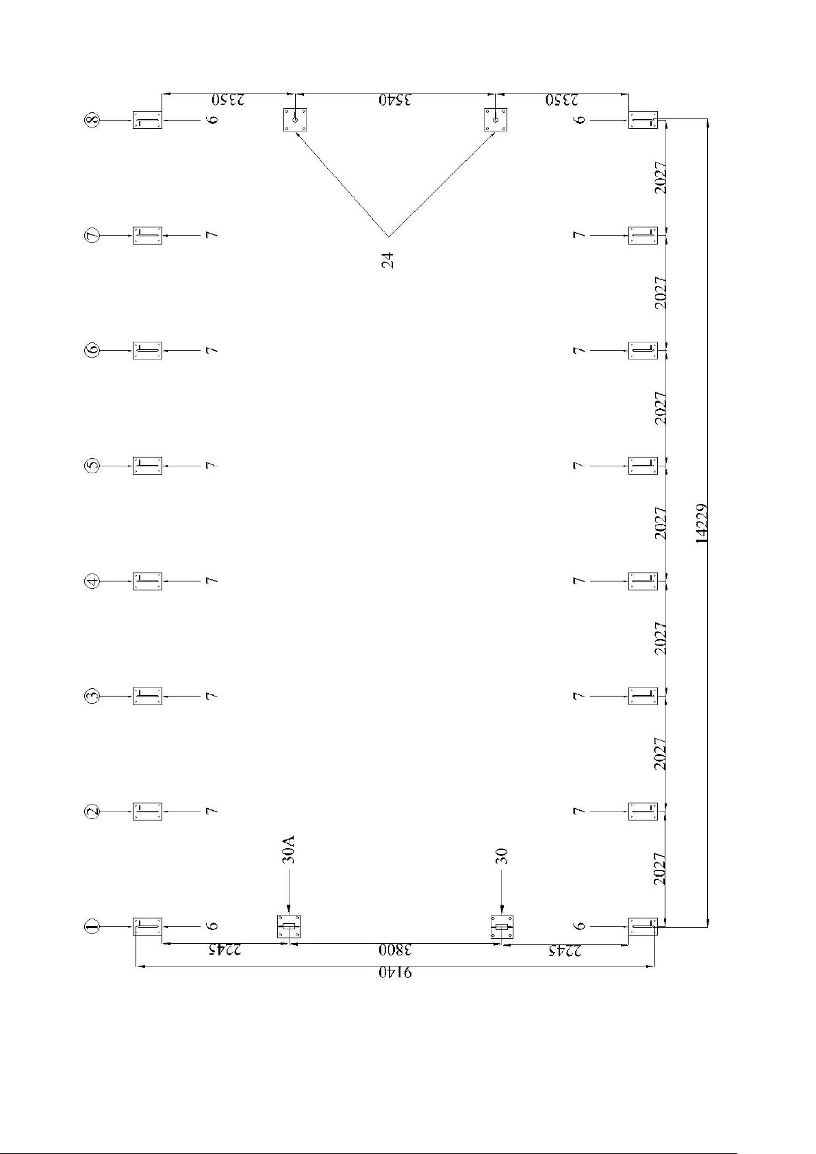
Page 9
Figure 1
Page 10
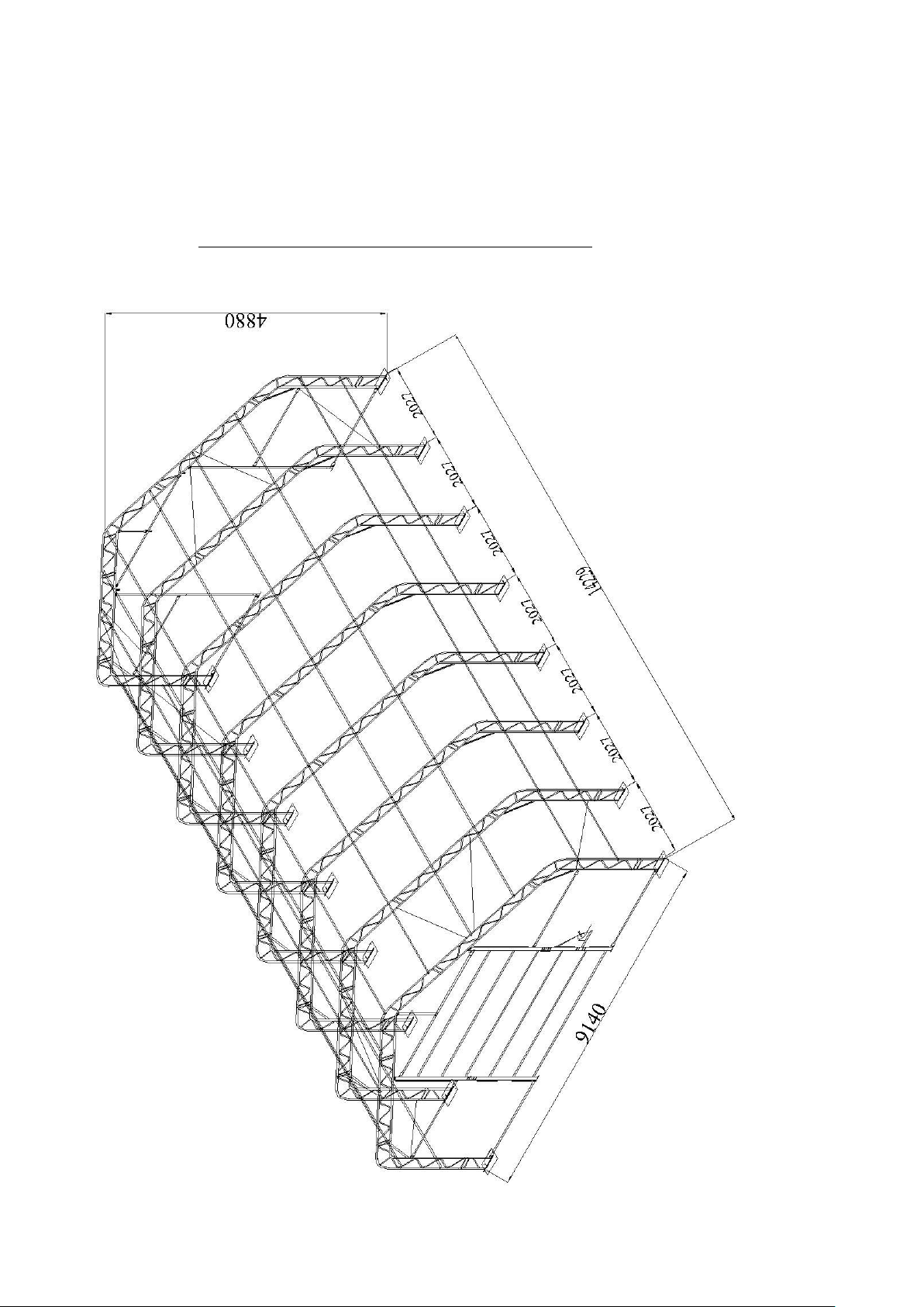
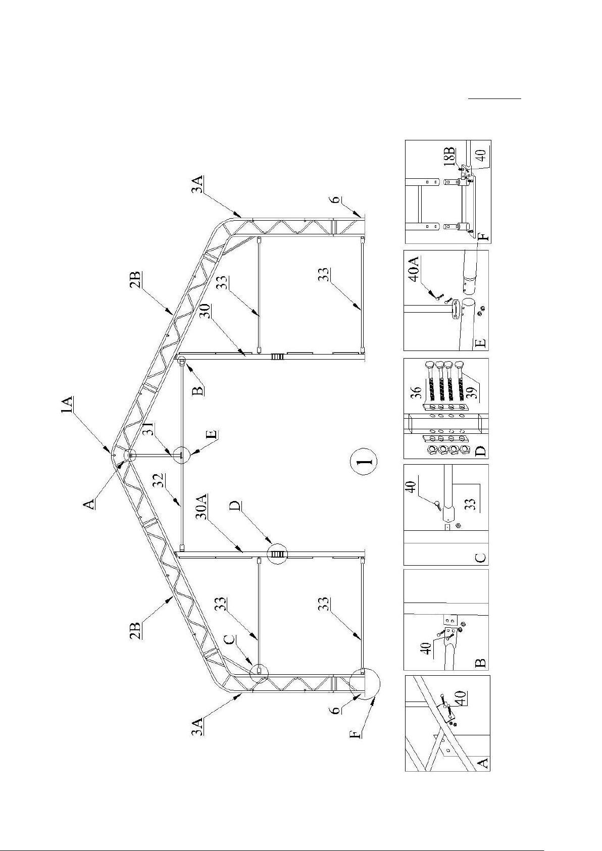
B—FRAME INSTALLATION (Arch No.1 to 8)
1. Find Truss Arches for front end (No.1A, 2B, 3A) and Base Plate (No.6) for Arch No.1 and
connect them by Bolt M8x60 (No.12).
2. Find relative parts of rails and portals for front end and assemble them referring to Figure 2.
Figure 2

Page 11
3. Find Truss Arches (No.1, 2, 3) for Arch No.2 to 7 and connect them by Bolt M8x60 (No.12).
Please refer to Figure 3 for details.
Figure 3
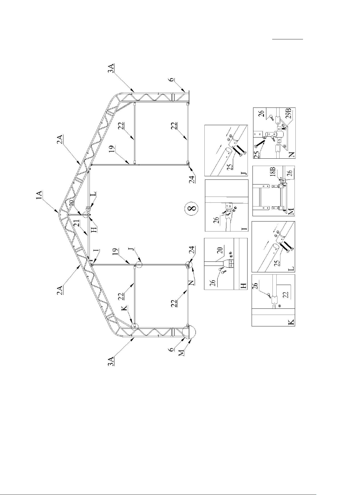
Page 12
4. Find Truss Arches for front end (No.1A, 2A, 3A) and Base Plate (No.6) for Arch No.8 and
connect them by Bolt M8x60 (No.12).
5. Find relative parts of rails and portals for back end and assemble them referring to Figure 4.
Figure 4

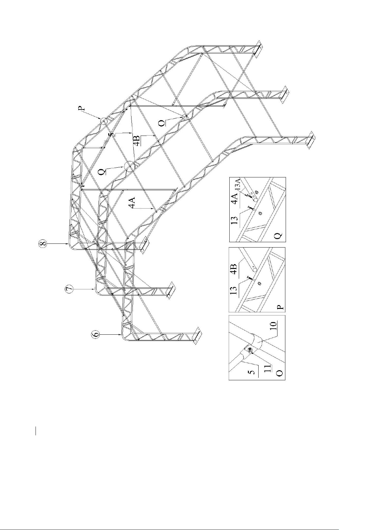
Page 13
6. Lift the assembled arches onto base plates.
7. When finish installing the first two arches, install Purlin (No. 4). Connect purlins by Bolt M8x50
(No.13A) and connect them to arch by Bolt M8x100 (No.13) and then go to Arch No.3 to No.7 and
Purlins (No.4A & 4B), one arch and purlin tubes in turns. Please refer to Figure 5 and Figure 6.
8. Install Bracing Tube (No.5) between arches by Tube Clip (No.10)
\
Figure 5
Page 14
Figure 6

Page 15
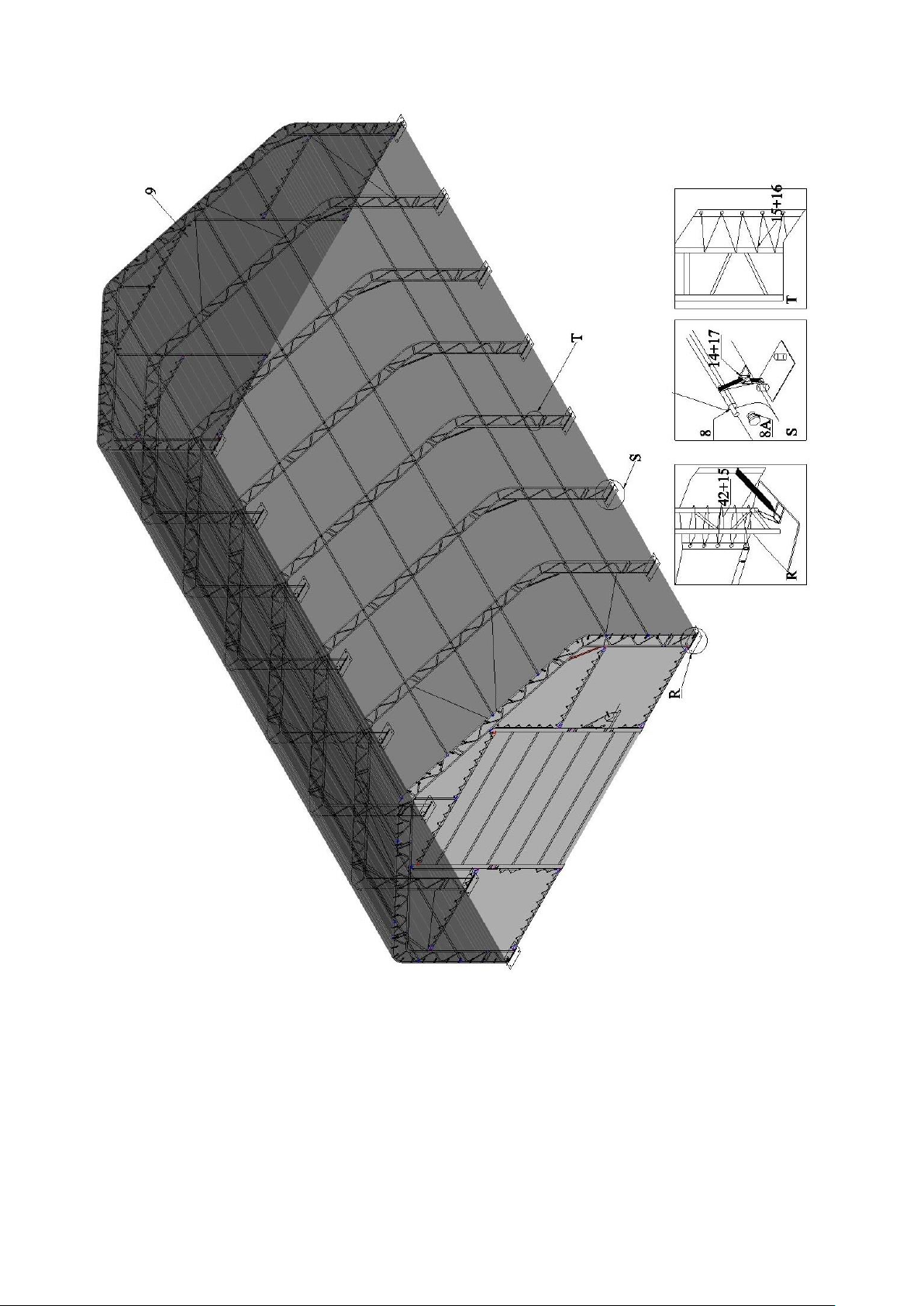
C-INSTALLING COVER
NOTE: DO NOT install the cover onto the frame of your building in high wind conditions. A slight
breeze is the most advantageous for cover installation. To take advantage of the breeze, pull the
cover up over the arches with the breeze blowing in the cover like a sail filled with air.
1. Roll out the roof cover on a ground sheet. Align the cover evenly to each end of the frame. Be
sure doing not over pull the end of roof cover.
2. Pull the cover over frame EVENLY, CAREFULLY AND SLOWLY. Insert tensioning tubes
(No.8) into the cover pipe pockets. Cut a small opening on the pipe pocket over against every
base plate. Put the Belt (No.17) around tensioning tube and then go through winch (No.14) and
loosely secure. DO NOT TIGHTEN. Adjust the cover so that it is square and evenly centered on
the frame.
Note: The end flaps must overhang evenly at both ends.
3. Use Cable Tie (No.16) to fix roof cover to end arches first. Then use the supplied Knitting Rope
(No.15) to tighten the roof cover to the end arches. The rope should be cut as your requirements
when using. The recommended procedure is to use separate pieces of rope and start by first
lacing the cover from the bottom edges up to the top center. Secure the ropes at the top center
and then apply tension as you lace down both sides. Fasten the rope at the bottom edge.
4. When roof cover is tidy and ready, drive the winch tie down forth and back and then roof cover
is tightened.
5. Tidy the cover. Pull the band inside the end of roof cover, make the cover well fold to end
arches and fasten the band.
6. Install Front and Back Cover (No.34&23) to front and back end wall by cable tie (No.42&28).
Note: if there is damage for cover when use, please repair it as soon as possible
to avoid further damage.
Page 16
ROOF COVER INSTALLATION
Figure 7
Page 17
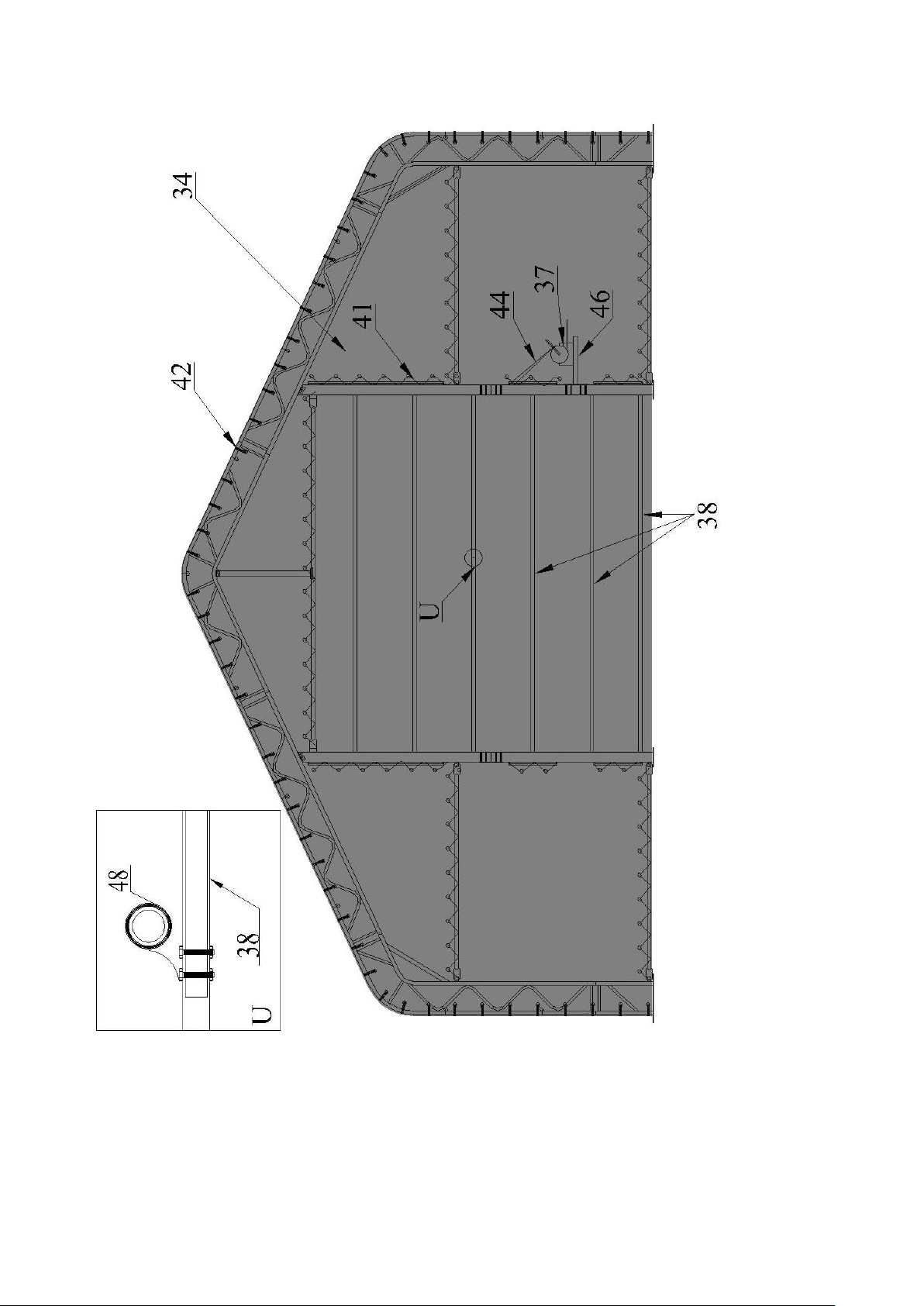
FRONT COVER AND MECHANICAL DOOR INSTALLATION
Figure 8

Page 18
MECHANICAL DOOR INSTALLATION
Figure 9
Page 19
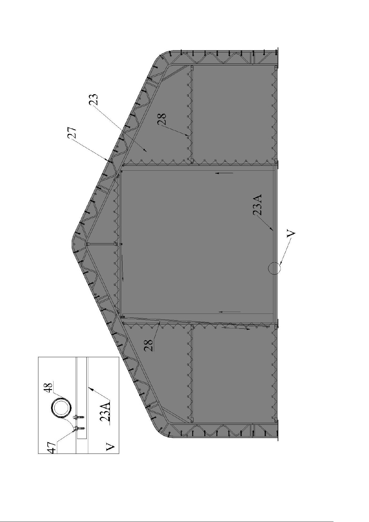
BACK COVER AND PULL EASE ROLL-UP DOOR INSTALLATION
Now your assembly is completed.
Figure 10
Table of contents
Popular Tent manuals by other brands


REDVERZ
REDVERZ Atacama Expedition Tent Setup instructions

Borrowed Spaces
Borrowed Spaces CHARLESTON PERGOLA YM11762 Installation and operating instructions

gaviota
gaviota VERTIKO Assembly instructions

Skanholz
Skanholz 242887 Assembly instructions

SereneLife
SereneLife SLSWNG350BL user manual

Skanholz
Skanholz Toulouse 371334 Aassembly Instructions


