Nordson iDry User manual

Instruction Sheet
Part 7790223A
E2010 Nordson Corporation
P/N 7790223A
iDryrInverter Inspection and Installation
Introduction
Use this sheet to inspect and connect a replacement iDry inverter assembly.
The inverter should always be inspected before being installed to make sure
all wiring is connected properly and securely.
Safety
Qualified Personnel
Equipment owners are responsible for making sure that Nordson equipment
is installed, operated, and serviced by qualified personnel.
Qualified personnel are those employees or contractors that
Shave experience operating and maintaining high-power and high-voltage
electrical equipment.
Scan safely perform their assigned tasks.
Sare familiar with all relevant safety rules and regulations and are
physically capable of performing their assigned tasks.
WARNING: The control enclosure and coil tray contain high voltages and
high power levels. Failure to ensure and employ all appropriate safety
measures may result in serious injury or death.
WARNING: HIGH VOLTAGE! Disconnect and lockout all power to the
system before perfoming any of the procedures in this section. Electrical
repairs should always be done by a qualified electrician with knowledge of
high voltage systems. Failure to observe this warning may result in fatal
injury to personnel.
WARNING: Never disarm any diagnostic device including but not limited to
the current sensor, overtemperature switches, air pressure switch, or coil
tray lid safety switches. Disarming diagnostic devices will void the warranty
and may cause equipment failure.

iDry Inverter Inspection and Installation
2
Part 7790223A E2010 Nordson Corporation
Unpacking
The inverter assembly is shipped up-side down in the box, bolted to a wood
panel and secured with a custom foam insert. Loose cables are looped and
secured to the assembly.
1. Open the box, then open the anti-static bag without cutting it, and lift the
wood panel and inverter assembly straight up and out of the box.
2. Remove the bag from the inverter assembly and place it right-side up on
a clean workbench. Remove the screws, lock washers, and flat washers
securing the inverter assembly to the wood panel.
3. Save all of the shipping materials and box to re-use if shipping a failed
inverter assembly back to Nordson Corporation.
Contact Nordson Customer Support at (800) 433−9319 for information on
returns and shipping.
Inspection
Inspect the inverter assembly for loose connections or damage before
installing it into the induction dryer.
1. See Figure 1. Check the indicated harness connectors at Q1, Q2, Q3,
and Q4 and the circuit board. Make sure they are connected properly
and securely according to the labeling on the IGBT Driver board, IGBT
Equalizer boards, and heatsink.
Q1 to J9 and J10 Q2 to J3 and J4
Q3 to J5 and J6 Q4 to J7 and J8
CAUTION: If the harness terminals are disconnected from Q1, Q2, Q3, and
Q4, do not touch the blade-type terminals. Skin oils and other contaminants
can affect the quality of the connection and lead to component failure.
2. See Figure 2. Cut the cable ties securing the two coiled cables and
three coiled harnesses to the inverter.
3. Check the harness connections to T1, TS1, and SC1.

iDry Inverter Inspection and Installation 3
Part 7790223A
E2010 Nordson Corporation
Q4 Q3 Q1 Q2
J9 J3
J5 J7
J6 J8
J10 J4
To J4
To J3
To J10To J9To J5 To J6
To J7
To J8
Ground
Fiber
Optic
A1+A2
15V
Power
J11
Figure 1 Q1−Q4 Connections
Keyed Plug
Right −White
Middle −Red
Left −Black
TS1 SC1
T1 To PCB8, 9
To Distribution Board
Terminal Block JS
409, 410, GND
Terminals (TBM) for
Coil Tank
Capacitor Cables
450,451 470,471,472
460,461
Figure 2 T1, TS1, and SC1 Connections

iDry Inverter Inspection and Installation
4
Part 7790223A E2010 Nordson Corporation
Inverter Replacement
WARNING: Turn off and lock out power at the plant disconnect to the iDry
Induction Dryer before opening the enclosure base doors. The dryer
internal disconnect does not remove all power to the unit. Wait 10 minutes
for the dryer’s internal capacitors to discharge. Failure to observe this
warning could result in personal injury or death.
NOTE: Remove the rear panel from the base to acess the inverter
assembly. Open the front doors to access the distribution board.
1. Turn off electrical power to the system at the plant disconnect and lock it
out. Wait 10 minutes for the dryer’s internal capacitors to discharge.
2. Open the back panel and verify that incoming power has been removed.
Turning off the front panel disconnect does not remove all power from
the system.
3. See Figure 2. At the inverter assembly terminal block TBM, disconnect
the coil tank capacitor cables 409, 410, and GND.
4. See Figure 3. Label and disconnect the two fiber-optic cables (A1, A2)
from the inverter assembly driver board. The cables are grey and blue,
and are polarity sensitive.
5. Disconnect the blue and white twisted pair 15V power cable from the
inverter assembly driver board terminal J11.
6. See Figure 4. Label and disconnect the cables and harness from the
following components:
SCable 407 at PCB8 (−), cable 408 at PCB9 (+).
SAt the Distribution Board terminal block J5:
Lead 450 451 Shield 471 472 470 460 461
Terminal 1 2 3 4 5 6 7 8
7. See Figure 1. Disconnect the ground cable from the ground stud on the
inverter assembly.
Fiber
Optic
Cables
J11
15V Power
A2
A1
Figure 3 Fiber-Optic Cable and 15V Power Connections

iDry Inverter Inspection and Installation 5
Part 7790223A
E2010 Nordson Corporation
CR1
JX2
DATUMDATUM 1
_______A
30KW SSR BOARD
S/N
R1
MADE IN USA
DATE
AI
C1
T
D1
R3
D2 R2
JX1 1
MV1
N314D00A
COMPONENT
1
2
3+
4−
AD
F C
B
2UF
CR1
_______A
30KW SSR BOARD
S/N
MADE IN USA
AI
C1
T
R3
D2 R2
JX1 1
MV1
N314D00A
COMPONENT
1
2
CR1
JX2
DATUMDATUM 1
_______A
30KW SSR BOARD
S/N
R1
MADE IN USA
DATE
AI T
D1
R3
D2 R2
MV1
N314D00A
COMPONENT
1
2
3+
4−
ÎÎÎÎÎÎÎÎÎÎÎÎÎÎÎÎÎÎÎÎÎÎÎÎÎÎÎÎ
NCBA
G
BACN
1
J11
J8
1
J7
1
J6
1
J5
1
J3
1
J4
1
J9
1
J10
1
410
409
T4
408
407
420
T
R2
E2
R1
IA
DATE
MADE IN USA
C2E1
B1
B1
W2
Q2 E1
W2B1
E2B2
J3
C1
S/N Q2
1069539A
30KW IGBT EQUALIZER BD
410
410
409
409
GND
3
I T
R2
E2
C2E1
A
R1 TE
MADE IN USA
1
2
J7
B1W2
E1 B1
W2
E2
B1
B2 Q4
1069539A
S/N
30KW IGBT EQUALIZER BD
J8
LF1
D1
OFF
O
C14
1
JP2
C15
J3
J2 1
1
R23
D9
D8 VR1
R25
R24
C17C16
−15V+15V
FREQUENCY
TANK V
INVERTER I
COMMON
D11
R32
D10
R31
1
J1
IA
TP4TP3TP2TP1
DATE
T
R30
VR2
R29
R28
R26
R27
C20
C22
C21
C19
C18
1
J4
C12
U2
U5
R1
D7
D6
D5
D2
JP1
1C13
R9
R10
R6
R5
R4
R3
R7
R12
RESET
FAULT
OVERTEMP
PWM
JX
1 1
JS
C7C10
U7
R13
R16
U6
U3
C2C5
C6 C9
C3
C11
R18
R17
R15
R11
D4 P1
U8
C8
R22
R21
R20
R19
MADE IN USA
CURRENT LIMIT
DISTRIBUTION BD
HI−I
R14
1069572A
30KW OVEN
LO−I S/N
J1
6ES7−214−2AD23−0XB0
CPU 24I/O
14 DC INPUTS
10 DC OUTPUTS
14
12
13
9
8
4
5
1
NO
14 3424
13NO NO3323
44 A2−
43NOA1+ NO
14 3424
13NO NO3323
44 A2−
43NOA1+
J2 A1
J3 A2
COM
140
TB110
24VDC
171
50 AMP
TB170
F1 A/B/C
MAINS
6ES7−231−7PD22−0XA0
6 AMP
DC POWER
COM24VDC
159 141
40 AMP
RF POWER
F2 A/B/C
TB138
25A
24VDC BLOWERS
F3 F4 A/B
PLC1
THERMOCOUPLE
4 INPUTS
6 AMP6 AMP
AIR HTR LN 1
F5 A/B F6 A/B
AIR HTR LN 2 6 AMP
MAGSEP
F7 A/B
CR4CR2MCR
CR1 CR3 PCB 1
J2
J1
J3
NO
14 3424
13NO NO3323
44 A2−
43NOA1+
JP2JP1
PCB 2
JX
RROUU
O
GG N
DD
N
INVERTER
DISTRIBUTION BOARD
TERMINAL BLOCK J5
PCB8
PCB9
Transformer
TOP VIEW
FRONT VIEW
COIL CABLE TERM. BLOCK (TBM)
406 408
18
REAR ACCESS PANEL
FRONT DOORS
407 405
Figure 4 iDry Dryer Base Component Location

iDry Inverter Inspection and Installation
6
Part 7790223A E2010 Nordson Corporation
Inverter Replacement (contd)
8. Remove the fasteners securing the inverter assembly from the
enclosure. Save the fasteners for use with the new inverter.
9. Install the new inverter assembly and secure it in place with the
fasteners removed in step 8.
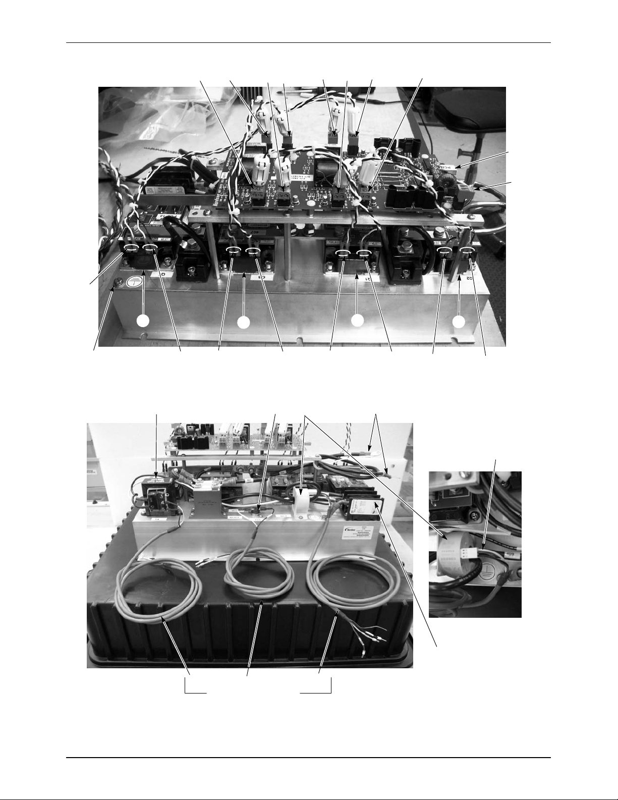
10. See Figure 3. Connect the blue and grey fiber-optic cables to the new
inverter assembly. Push the connectors into the receptacles until they
click.
NOTE: If you connect the fiber-optic cables incorrectly you will get an
Out of Lock fault. Reverse the cables to clear the fault.
11. Connect the blue and white twisted pair 15V power cable to the inverter
assembly driver board terminal J11.
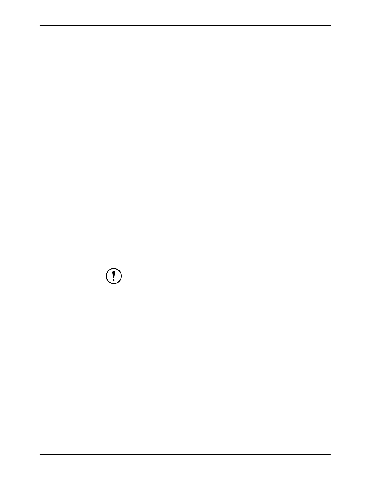
12. See Figure 2. Connect the coil tank capacitor cables 409, 410, and
GND to the terminal block (TBM) on the inverter board. Make sure you
do not connect either the 409 or 410 cables to the ground terminal.
13. See Figure 4. Connect cable 407 to PCB8 (−) and cable 408 to
PCB9 (+).
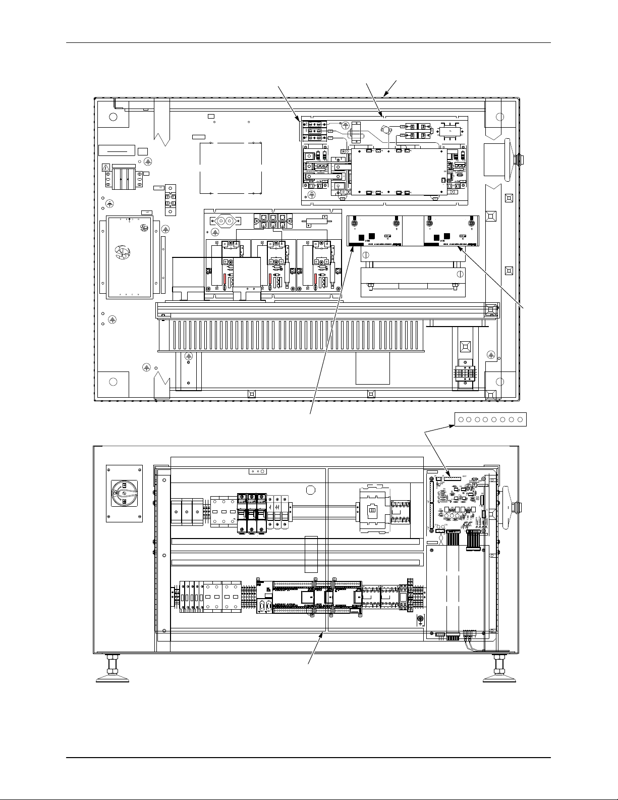
14. Connect the inverter assembly harnesses to the Distribution Board
terminal block J5 as described in the table on page 4, step 6.
15. See Figure 1. Connect the system ground wire (heavy green and yellow
wire) to the ground screw at the corner of the heat sink.
16. Install the rear panel on the base. Make sure to connect the panel
ground wire to the base.
17. See Figure 5. If shipping the old inverter assembly back to Nordson
Corporation:
a. Secure the assembly to the wood panel (1) with the shipping screws,
flat washers, and lock washers (2, 3, 4).
b. Pull the anti-static bag (5) over the assembly.
c. Turn the inverter assembly upside down and place it into the custom
foam insert (6) in the shipping box.
d. Close the anti-static bag and tape the opening shut. If removed,
place the bag of silica gel dessicant (7) in the box.

iDry Inverter Inspection and Installation 7
Part 7790223A
E2010 Nordson Corporation
1
2
3
4
5
6
7
Figure 5 Inverter Assembly Packaging
1. Wood panel
2. Screws
3. Lockwashers
4. Flat washers
5. Anti-static bag
6. Foam insert
7. Silica gel dessicant

iDry Inverter Inspection and Installation
8
Part 7790223A E2010 Nordson Corporation
Issued 8/2010
Original copyright date 2010. iDry, Nordson and the Nordson logo are registered trademarks of Nordson Corporation.
Table of contents
Popular Inverter manuals by other brands

Ferm
Ferm FGG-800 Original instructions

Haier
Haier AS50PDAHRA Service manual

Fuji Electric
Fuji Electric FRN0001C2S-2AFRN0002C2S-2AFRN0004C2S-2AFRN0006C2S-2AFRN0010C2S-2AFRN0012C2S-2AFRN0020C2S-2AFRN0025C2S-2AFRN0033C2S-2AFR instruction manual

Axpert
Axpert MLV 5KVA-48V user manual

Mitsubishi Electric
Mitsubishi Electric 800 Series Hardware instruction manual

AL-KO
AL-KO 2000i manual

Grape Solar
Grape Solar GoCharger10 user manual

ULTRA BRIGHT
ULTRA BRIGHT UB-SFPL-S-4 Series instructions

Sofar
Sofar HYD3000-ES user manual

Priefert
Priefert Q36-98 installation instructions

Tektronix
Tektronix PPG3000 Series Declassification and security instructions

GE
GE HOME NERATOR SYSTEM 45000 WATT - Installation and start-up manual