Nordson 3100V Series User manual

Issued 4/98 1O1EN–OPC–[3V–237532]–12
Nordson Corporation
OPERATOR’S CARD
P/N 237 532A
Series 3100
V
/3400
V
Hot Melt Material Applicator
with AC Constant-Speed Gear Pump, Standard Filter, Pattern Control
Please Note
The operator’s card contains only information
necessary for daily operation and maintenance.
For other information, refer to the product manual.
A copy of this operator’s card and an order form for
another operator’s card are included in the
introduction part of the operating manual.
WARNING: Allow only qualified personnel to
perform the following tasks. Observe and
follow the safety instructions in this document
and all other related documentation.
Always follow the instructions given in the
operator’s card and operating manual.
Always follow instructions in the material supplier’s
Material Safety Data Sheet (MSDS) or material
information sheet.
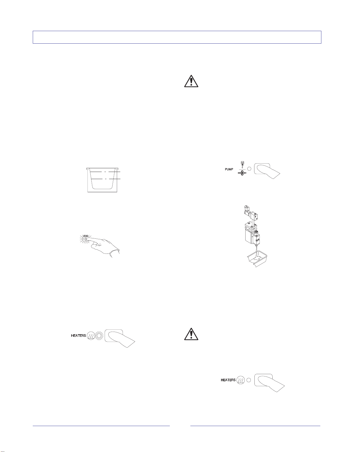
Even at recommended operating temperatures,
hot melt material may release vapors. Exceeding
prescribed processing temperatures for long
periods of time can result in dangerous
decomposition by-products. Remove vapors
by drawing them off with an exhaust system.
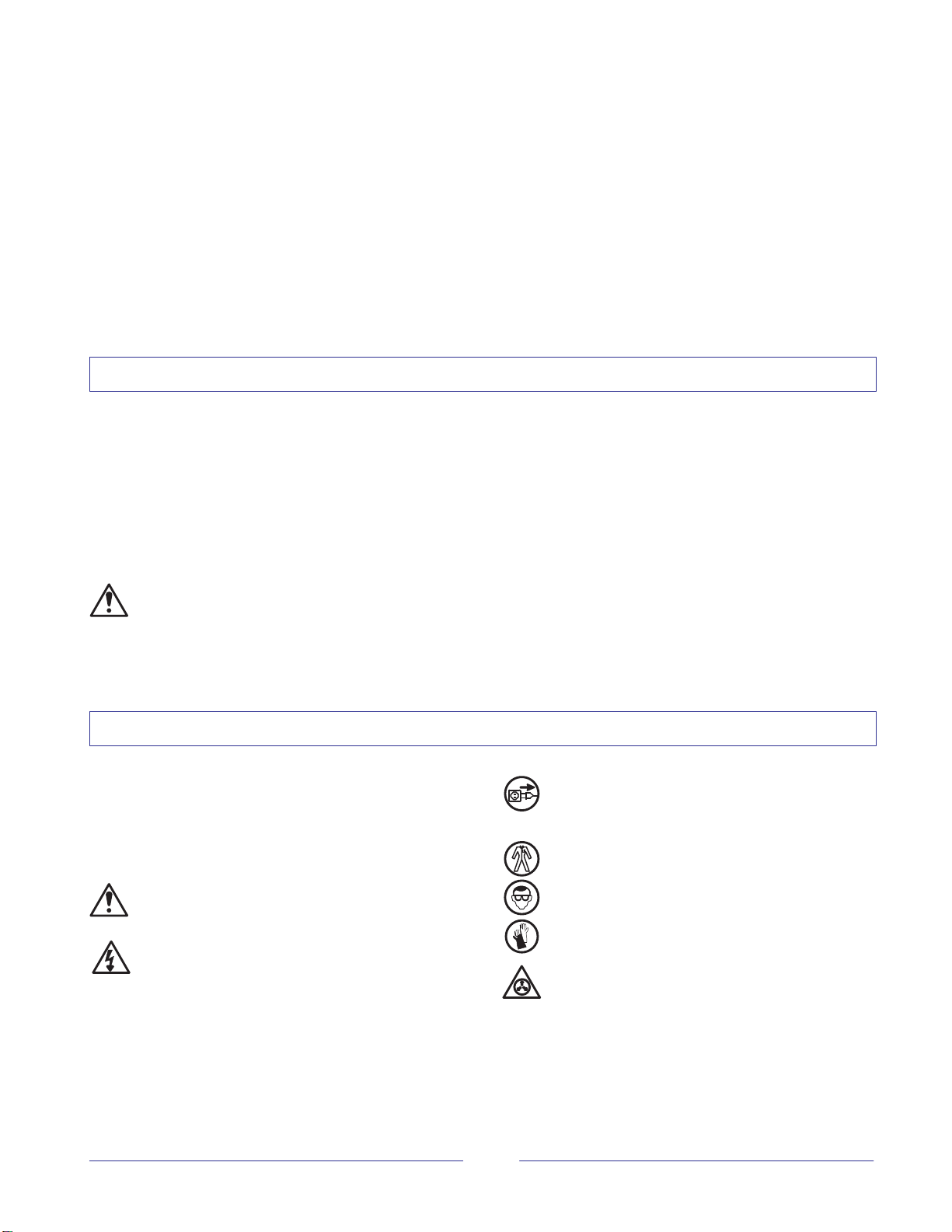
Safety Symbols
The following symbols warn against dangers or
possible sources of danger. Become familiar with
them! Failure to heed a warning symbol can lead to
personal injury and/or damage to the unit or other
equipment.
WARNING: Failure to observe can result in
equipment damage, personal injury, or death.
WARNING: Risk of electrical shock. Failure to
observe can result in personal injury or death.
WARNING: Disconnect equipment from line
voltage. Failure to observe can result in
personal injury or death.
WARNING: Hot! Risk of burns. Wear
heat-protective clothing, safety goggles, and/or
heat-protective gloves depending on the
symbol or symbols shown. Failure to observe
can result in personal injury or death.
WARNING: Pressurized system or material.
Release pressure. Failure to observe can
result in serious burns.

Issued 4/98
2
O1EN–OPC–[3V–237532]–12
Overview of System Components
1
2
3
4
7
5
6
Applicator
1. Motor and pump assembly
2. Tank
3. Filter, drain valve, and pressure control valve
4. Controls
Additional System Components
5. Hose
6. Air-operated gun
7. Solenoid valve
Daily Maintenance
1. Clean the exterior surfaces of the applicator and
guns.
2. Check the o-rings and gaskets for leaks.
3. Flush the manifold filter as follows:
a. Turn the pump off by pressing the PUMP key.
The PUMP light will turn off and the pump will
stop.
b. Place containers under all guns and trigger the
guns to relieve hydraulic pressure.
c. Open the drain valve over a container by
turning the valve counterclockwise.
d. Turn the pump on by pressing the PUMP key.
Wait until a steady stream of adhesive flows
from the drain valve.
e. Turn the pump off by pressing the PUMP key.
f. Close the drain valve.
g. Turn the pump on by pressing the PUMP key.

Issued 4/98 3O1EN–OPC–[3V–237532]–12
Daily Startup/Shutdown
Automatic Startup/Shutdown
With the seven-day clock and pattern control features
on, the following occur:
1. The heaters and pattern control turn on
automatically. When the READY light turns on,
you must press the PUMP key to start the pump.
2. The heaters and pump turn off automatically and
the system shuts itself down.
Manual Startup
1. Check the adhesive level. If the level is below
50%, add adhesive to the tank. Fill to within
25 mm (1 inch) of the tank top.
25 mm
50%
2. Close the lid immediately to prevent contamination
of the adhesive.
3. If the POWER switch is off, turn it on.
4. Prepare each gun in your system for operation as
follows:
Air-operated guns: turn on the operating air.
Handguns: unlock the trigger.
Electric guns: turn on the gun driver.
5. Press the HEATERS key. The HEATERS light will
turn on and the unit will begin to heat.
6. Check the temperature setting for each heated
zone.
7. If the pattern control is not on, press the PATTERN
CONTROL key. The PATTERN CONTROL light
will turn on.
8. When the READY light turns on, press the PUMP
key.
WARNING: When the tank lid is open, hot melt
vapors may be released. Vent the application
area or wear a respirator for protection from
vapors.
9. Check the adhesive level periodically. Refill the
tank before the level drops below 50%.
Manual Shutdown
1. Press the PUMP key. The PUMP light will turn off
and the pump will stop.
2. Place containers beneath all guns and trigger the
guns to relieve hydraulic pressure.
3. Use one of the following methods to prevent
accidental gun triggering:
Air-operated guns: reduce air pressure to 0.
Handguns: place the trigger safety in the
locked position.
Electric guns: turn off the gun driver.
WARNING: Never hang a handgun by its
trigger. The gun can accidentally discharge
material, causing burns.
4. Press the HEATERS key. The HEATERS light will
turn off.

Issued 4/98
4
O1EN–OPC–[3V–237532]–12
Vista Control Panel
3
2
1
27
25
24
18
17
16
15
14
13
11
10
9
8
7
4 5 6
23 22 20 19
21
12
26
1. Up key for selector display
2. Up key for multipurpose display
3. Selector display
4. Multipurpose display
5. FAULT light
6. READY light
7. Actual temperature display
8. Down key for multipurpose display
9. Enter key
10. Zone indicator lights
11. STANDBY or SETPOINT
temperature light
12. SYSTEM SETTINGS light
13. Up key for system settings
14. Down key for system settings
15. Move right key
16. Clock INTERVAL lights
17. Bead position 1 through 4 lights
18. POWER switch
19. LINE SPEED light
20. STORE light
21. USE light
22. Output lights
23. Test output keys
24. Output lights
25. SENSOR light
26. PATTERN CONTROL On/Off key
27. Control keys

Issued 4/98 5O1EN–OPC–[3V–237532]–12
Record of Vista Control Settings
Temperature Settings
Zone
Type
Zone 1 Temperatures Zone 2 Temperatures Zone 3 Temperatures
T
ype Operating Standby Band Operating Standby Band Operating Standby Band
Internal
Hose
Gun
Zone
Type
Zone 4 Temperatures Zone 5 Temperatures Zone 6 Temperatures
T
ype Operating Standby Band Operating Standby Band Operating Standby Band
Hose
Gun
Clock Settings
Heater Intervals Monday Tuesday Wednesday Thursday Friday Saturday Sunday
Heaters On-1
Heaters Off-1
Heaters On-2
Heaters Off-2
Standby Intervals
Standby On-1
Standby Off-1
Standby On-2
Standby Off-2
System Settings
System ready time delay: Startup: jSequential / jSimultaneous
Overtemperature setpoint: Auto-energize heaters: jOn / jOff
Global temperature band: Auto-energize pattern control: jOn / jOff
Warning or power output: jWarning / jPower on
Ready or pump output: jReady / jPump on
Password: jOn / jOff
Pattern Control Settings
Pattern
N mber
Output
Channel
Bead Positions Line Speed
N
um
b
er
Ch
anne
l
1 (Delay) 2 (Duration) 3 (Delay) 4 (Duration)
1 1
2
2 1
2

Issued 4/98
6
O1EN–OPC–[3V–237532]–12
Daily Operations
To do this . . . Press this key . . . This happens . . . It means . . .
Turn the power on. The POWER switch turns on. Power to the unit is on.
Turn the power off. The POWER switch turns off. Power to the unit is off.
Scan the temperatures
of each zone. The MONITOR/SCAN light
turns on and stays on. The system scans each
heated zone and displays
each zone’s temperature.
Monitor the temperature
of a zone. The MONITOR/SCAN light
stays on. The system displays the
temperature of only the
zone currently selected.
Place the system in
standby. The STANDBY light turns on. Heating zones hold at
your preset standby
temperatures.
Take the system out of
standby. The STANDBY light turns off. Heating zones return to
your operating setpoint
temperatures.
Turn the heaters on. The HEATERS light turns on. The tank, hoses, and
guns are heated.
Turn the heaters off. The HEATERS light turns off. No heat is applied to
system components.
Turn the 7-day clock on. The CLOCK light turns on. The system performs
functions controlled by
the clock.
Turn the 7-day clock off. The CLOCK light turns off. The system does not
perform functions
controlled by the clock.
Turn the pump on. The PUMP light turns on. The pump draws melted
material through the
system.
Turn the pump off. The PUMP light turns off. The pump stops drawing
melted material through
the system.
Determine whether a
fault was corrected. All LED lights turn on while
the system begins a
five-second test. At the end
of the test, the FAULT light
turns off.
The fault was corrected.
All LED lights turn on while
the system begins a
five-second test. At the end
of the test, the FAULT light
stays on.
The fault was not
corrected.
Turn the Pattern
Control on. The PATTERN CONTROL
light turns on. The system applies your
preset patterns.
Turn the Pattern
Control off. The PATTERN CONTROL
light turns off. The pattern control is off.
Original copyright date 1/98. Nordson is a registered trademark of Nordson Corporation.
Other manuals for 3100V Series
2
This manual suits for next models
1
Table of contents