5
All models are shipped from the factory with the
following:
1. Zero clearance to combustibles
2. Multi-speed direct-drive blower.
3. Blower Speed Relay.
4. Horizontal or Down flow duct connections.
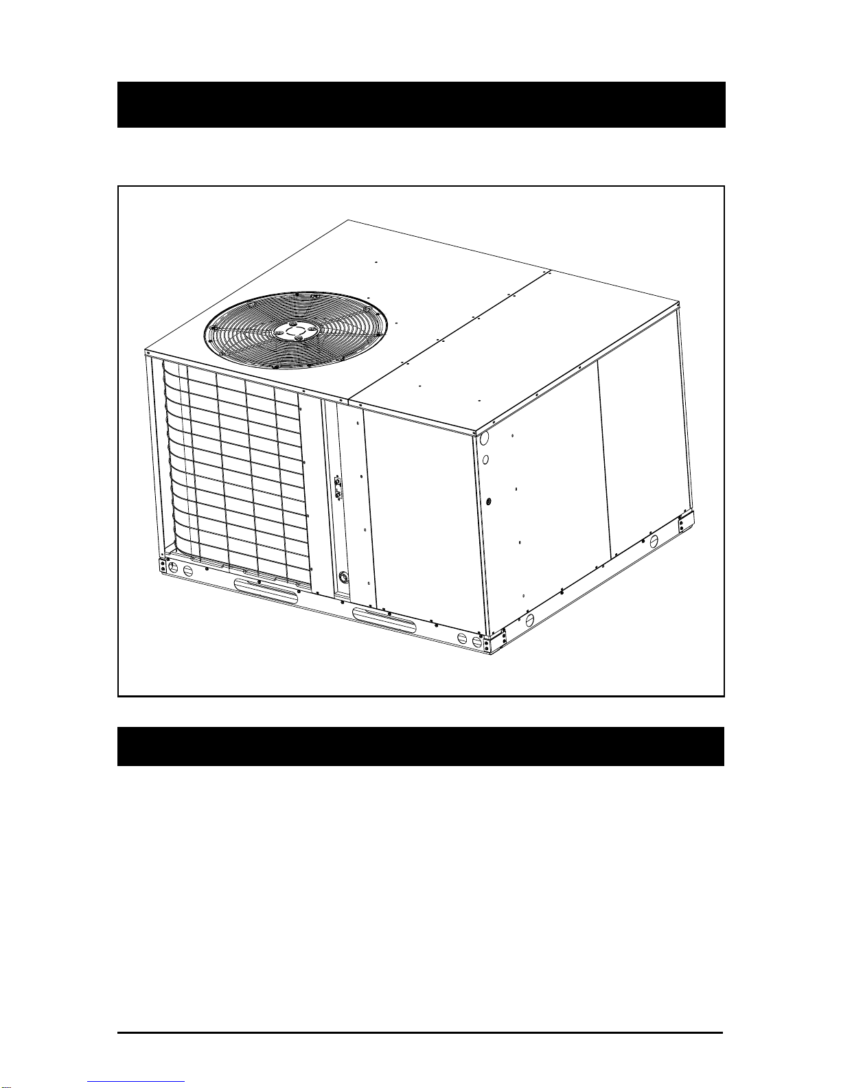
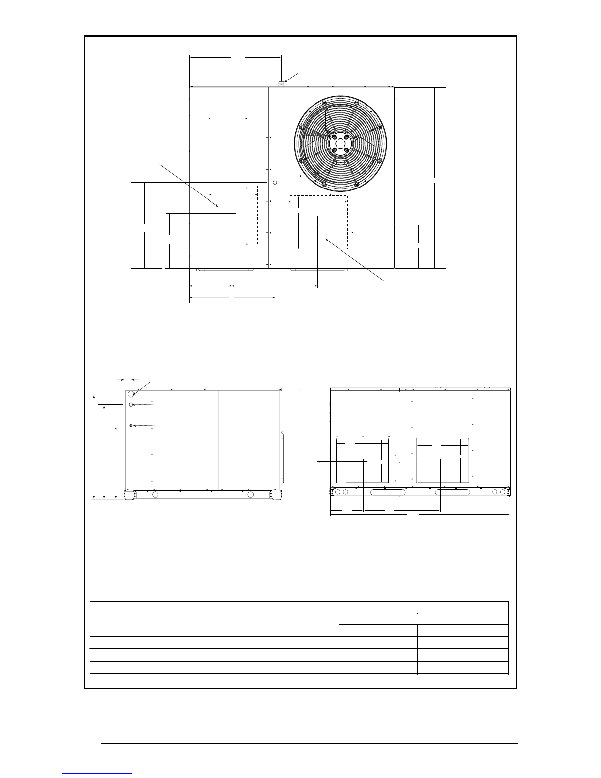
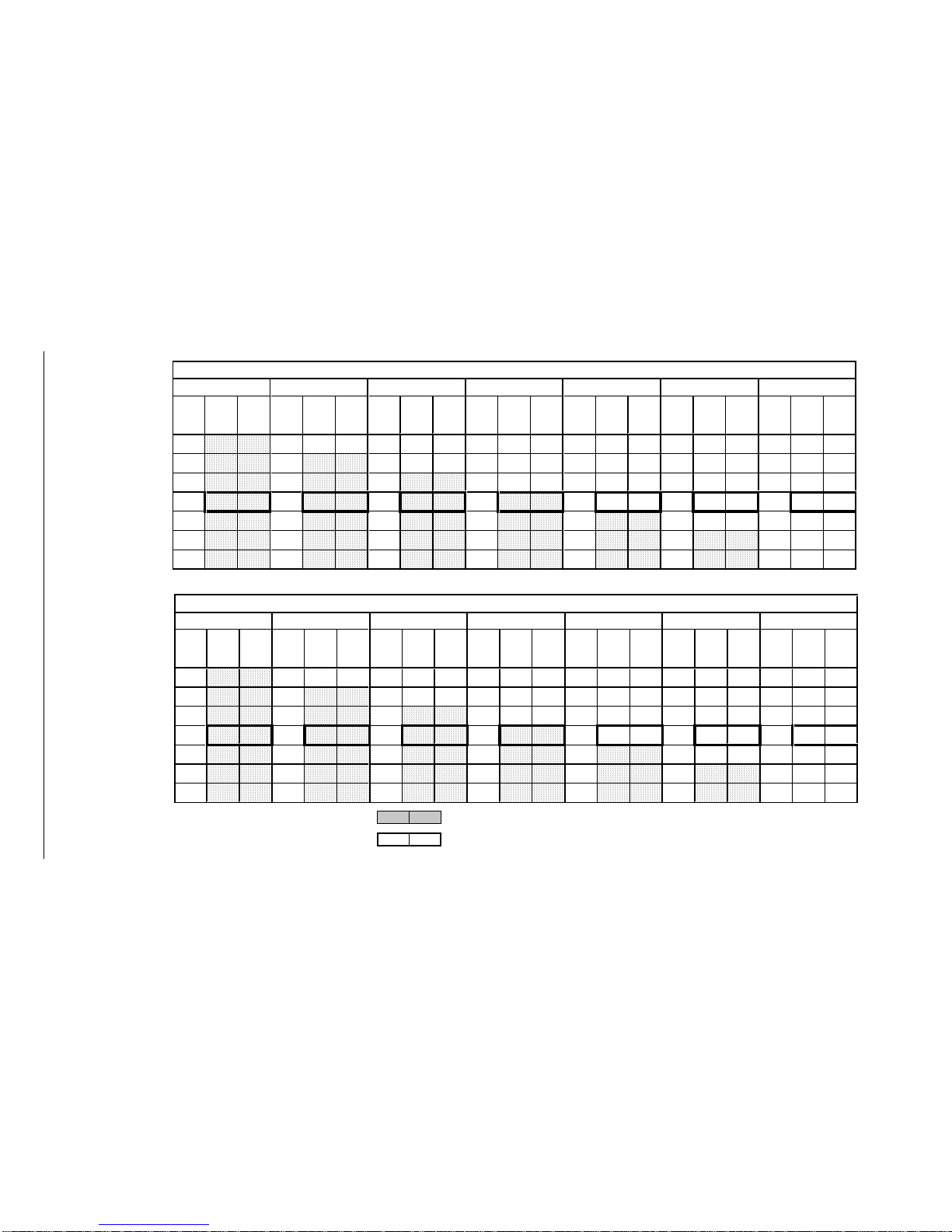
The unit dimensions are shown in Figure 3.
Optional field-installed electric heater kits are
available in 9 kw and 15 kw heating capacities.
A separate installation instruction document for
the electric heaters and their application
accompaniesthisone. Atwostageheat24VAC
thermostat should be used with electric heater
kits installed.
SAFETY CONSIDERATIONS
It is the responsibility of the installer to ensure
that the installation is made in accordance with
all applicable local and national codes.
!WARNING:
Improper installation, service,
adjustment,ormaintenancemaycause
explosion,fire,electricalshockorother
hazardousconditionswhichmayresult
in personal injury or property damage.
Unless otherwise noted in these
instructions, only factory authorized
kits or accessories may be used with
thisproduct. Noncompliancemayvoid
the unit’s warranty.
Labels, Tags —When working with this
equipment, follow all precautions in the
literature, on tags, and on labels provided with
the unit and/or approved field installed kits.
The type of hazard and severity are described
on each label or tag.
Pressures Within The System —This
equipment contains liquid and gaseous
refrigerant under high pressure. Installation or
servicing should only be performed by qualified
trained personnel thoroughly familiar with this
type equipment.
INSTALLATION REQUIREMENTS
Equipment Check —Before beginning the
installation, verify that the unit model is correct
for the job. The unit model number is printed on
the data label. All units have been securely
packaged at the point of shipment. After
unpacking the unit, carefully inspect it for
apparent and concealed damage. Claims for
damage should be filed with the carrier by the
consignee.
RequirementsandCodes—Theinstallermust
comply with all local codes and regulations
which govern this type equipment. Local codes
and regulations take precedence over any
recommendations contained in these
instructions. All electrical wiring must be made
in accordance with local codes and regulations
andwiththeNationalElectricCode(ANSI/NFPA
70) or in Canada the Canadian Electric Code
Part 1 CSA C.22.1. Air Ducts must be installed
inaccordancewiththestandardsoftheNational
Fire Protection Association “Standards for
Installation of Air Conditioning and Ventilation
Systems”(NFPA90A),“StandardforInstallation
of Residence Type Warm Air Heating and Air
Conditioning Systems” (NFPA 90B), these
instructions and all applicable local codes.
NFPA publications are available by writing:
National Fire Protection Association
Batterymarch Park
Quincy, Maine 02269
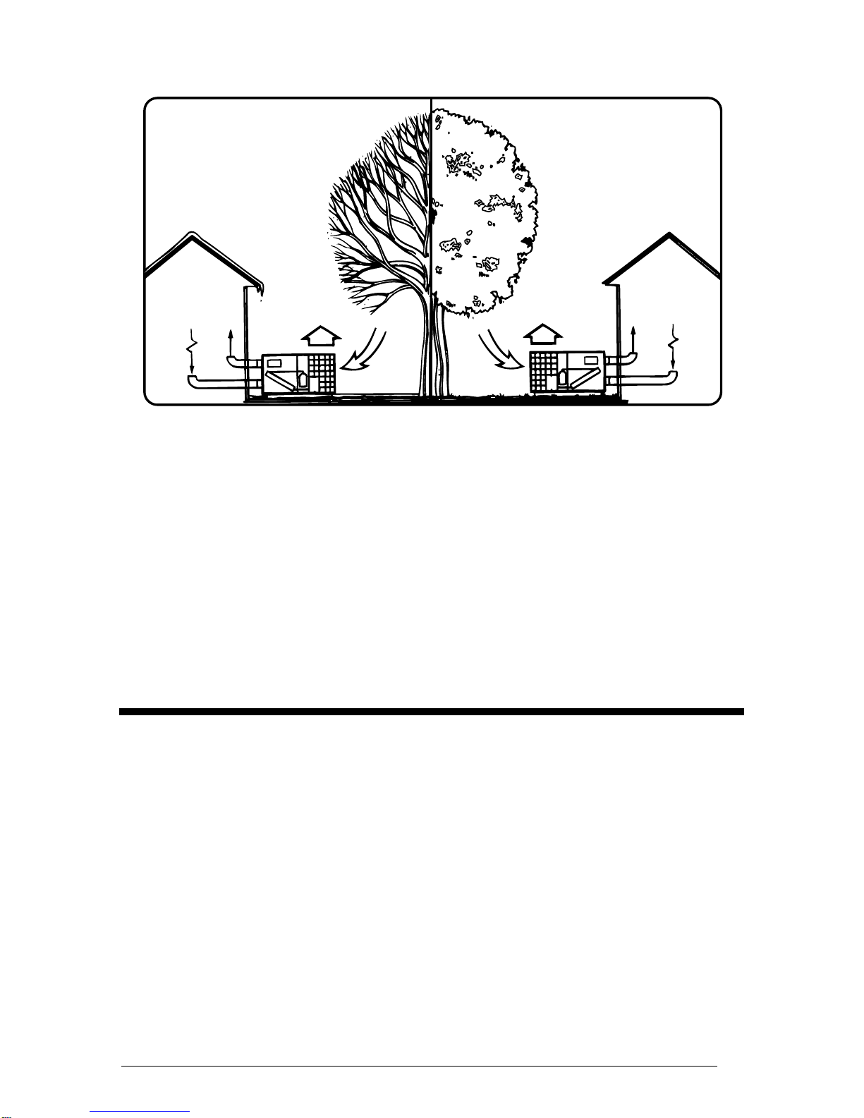
Unit Location —The Q4 series heat pump is
designedonlyforoutdoorinstallations.Choosing
the location of the unit should be based on
minimizing the length of the supply and return
ducts. Consideration should also be given to
availability of electric power, service access,
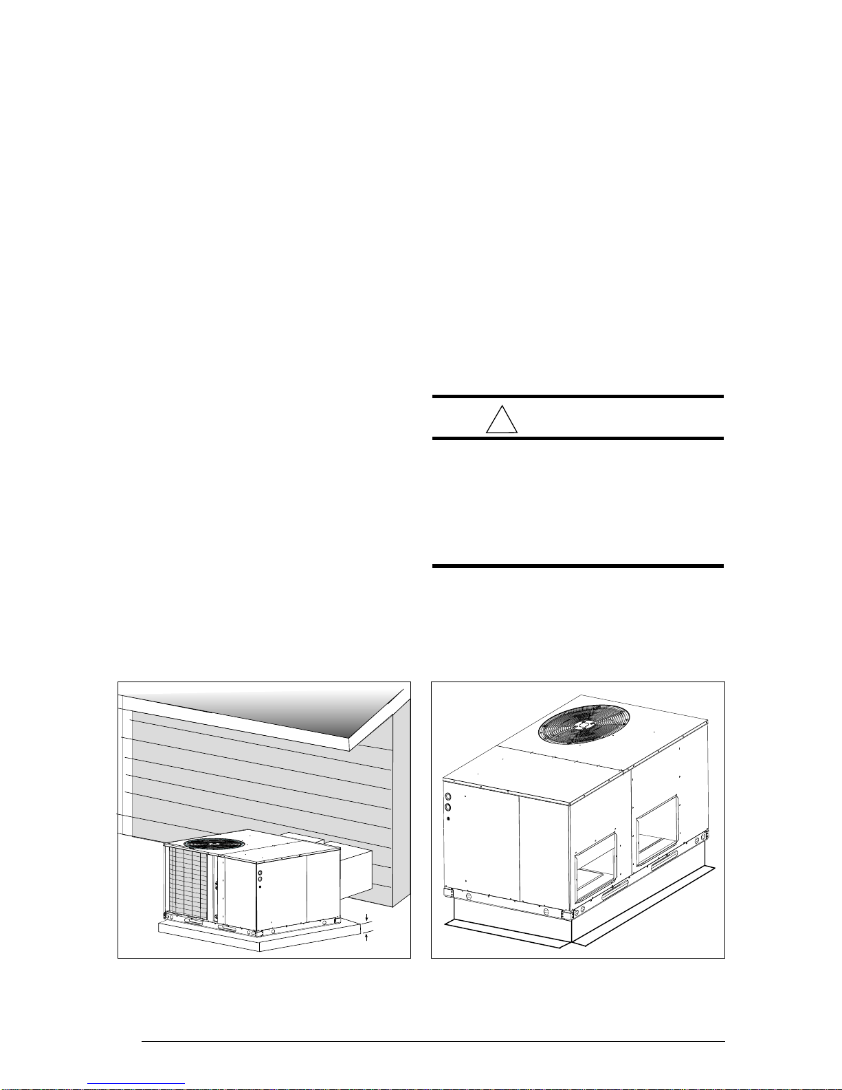
noise, and shade. Sufficient clearance for
unobstructed airflow through the outdoor coil
must be maintained in order to achieve rated
performance See Figure 4 for minimum
clearances to obstructions.
AirFilters—Asuitableairfiltermustbeinstalled
in the return air system. Air filter pressure drop
must not exceed 0.08 inches w.c. at 300 fpm.
Condensate Drain —Condensate is removed
from the unit through the 3/4" female pipe fitting
locatedonthefrontsideoftheunit. (SeeFigure
5.) Install a 2 inch condensate trap in the drain
line of the same size and prime with water.
Whenconnectingrigiddrainline,holdthefemale
fitting with a wrench to prevent twisting. Do not
over tighten! Refer to local codes and
restrictions for proper condensate disposal
requirements.