Norecs ProboStat How to use

Complementary Material to ProboStat™ Manual
2
ProboStat™ Starting Guide
As we are always learning from feedback from our customers and users, and for giving better understanding of
the ProboStat™ sample holder, we present this note as a complementary material to the ProboStat™ Manual.
The main goal of this document is explanation of the ProboStat™ system design which is not covered in the
Manual.
1. ProboStat™ Gas Supply System
1.1. Recommended reading
First, we recommend familiarizing youself with:
a) ProboStat™ Manual:
Part 2 “Safety first”, pp. 2-1 –2-2,
Part 4.2.4 “Gas connects”, pp. 4-5 –4-7,
Part 4.4 “Support tubes”, pp. 4-12 –4.13,
Part 4.5 “Gas supply tubes”, pp. 4-13 –4-14,
Part 6.3 “Pressures, vacuum, leakage rates, atmosphere purity”, pp. 6-1 –6-2,
Part 7.3 “Gas tightness”, pp. 7-4 –7-5,
Part 9.3 “Over-atmospheric pressure”, pp. 9-3 –9-4,
Part 9.4 “Wet gases with dew-point above room temperature”, p. 9-4,
Part 12.1.4 “Inner gas tubes”, pp. 12-4 –12-6.
b) NorECs web page www.norecs.com :
FAQ –atmosphere control
FAQ –sealing
1.2. Single and dual atmosphere modes
The ProboStat™ is a sample holder designed to perform experiments in single or dual atmosphere modes
at near-atmospheric total pressure, and can be fed with virtually any gas.
1.2.1.
Single atmosphere mode
The term “single atmosphere mode” means that one gas is fed in both inner and outer ProboStat™gas
compartments. The single atmosphere mode is used for:

Complementary Material to ProboStat™ Manual
3
2-point impedance spectroscopy and conductivity measurements on disk sample
2-point conductivity measurements on disk sample with surface guard
4-point conductivity measurement on disk sample (van der Pauw geometry)
4-point conductivity measurement on bar sample
Seebeck coefficient measurements
Annealing and sintering under controlled atmospheres
1.2.2.
Dual atmosphere mode
The term “dual atmosphere mode”means that the inner gas compartment is gas-tight separated from the
outer gas compartment. Achieving this separation is a process we call sealing. Then sealed the inner and
outer compartments can be fed with different gases or gas mixtures.
The dual atmosphere mode is used for:
Transport number measurements
SOFC and SOEC test and characterization
Running electrochemical reactors / electrochemical pumping
Permeability measurements
1.3. Gas connects, stems and stubs
1.3.1.
Gas connects
The gas connects mounted on the base unit hexagon are by default Swagelok quick-connects. In the high-
temperature base units the quick-connects are replaced by Swagelok bulkheads and mounted on the top
part of the splitted hexagon.
The stainless steel (SS) base unit has SS gas lines and SS quick-connects (steel colour). The Ni-coated
brass base unit has copper gas lines, and brass quick-connects (yellow colour).
The inner and outer ProboStat gas compartments are marked “INNER” and “OUTER”. Each compartment
has gas inlet and outlet quick-connects appropriately marked “IN” and “OUT”, resulting in “INNER IN”,
“INNER OUT”, “OUTER IN”, and “OUTER OUT”. The “IN”s are quick-connects with valves that are closed
when matching stems are disconnected. The “OUTER” connectors are always open.
Table 1. Swagelok gas connects.
Part no.
Type
Material
Valve
Function
B-QM2-B1-200
Quick-connect
brass
yes
Gas IN
B-QM2-B1-200MB
Quick-connect
brass
no
Gas OUT
SS-QM2-B1-200
Quick-connect
SS316
yes
Gas IN
SS-QM2-B1-200MB
Quick-connect
SS316
no
Gas OUT
SS-200-61
Bulkhead
SS316
no
Gas IN, Gas OUT

Complementary Material to ProboStat™ Manual
4
Fig. 1: SS and brass base units.
Fig. 2: IN and OUT quick-
connects for INNER
and OUTER gas
compartments.
Fig. 3: SS bulkheads mounted
on top part of splitted
hexagon.
1.3.2.
Gas stems
As standard, the quick-connects are matched by four quick-connect stems for connecting to 1/8’’ tubing.
The tubing material must be suitable for the gas used, and softer material than the ferrules of the stem.
Fig. 4: Brass quick-connect stem with
valve, for “IN”s.
Fig. 5: Brass quick-connect stem
without valve, for “OUT”s.
The valve on the stems opens only when plugged to a quick-connect with valve. To plug or unplug a stem
pull/push it into the quick-connect while holding back the rasterized collar.
We recommend having some spare parts for gas connectors and stems, namely Swagelok brass and/or SS
ferrule sets, parts no. B-200-SET and SS-200-SET accordingly.

Complementary Material to ProboStat™ Manual
5
Table 2: Swagelok gas stems.
Part no.
Material
Valve
Function
Match to
B-QM2-D-200
Brass
yes
Gas IN
B-QM2-B1-200
B-QM2-S-200
Brass
no
Gas OUT
B-QM2-B1-200MB
SS-QM2-D-200
SS316
yes
Gas IN
SS-QM2-B1-200
SS-QM2-S-200
SS316
no
Gas OUT
SS-QM2-B1-200MB
1.3.3.
Gas stubs
The inner IN and outer IN base unit gas lines are extended to the high temperature zone by various gas
supply tubes mounted on the base unit using gas stubs and piece of silicone hose.
The gas stub for the inner gas compartment is made of PEEK and assembled by a Viton sealing O-ring. The
PEEK gas stub is screwed onto the upper part of base unit body.
The gas stub for the outer gas compartment is made of SS and assembled by two Viton sealing O-ring. The
SS gas stub is set into the lower part of base unit body.
Fig. 6: ProboStat™ PEEK and SS gas stubs
Fig. 7: ProboStat™ base unit with gas stubs
mounted.

Complementary Material to ProboStat™ Manual
6
1.4. Base unit sealing O-rings
The ProboStat base units can be supplied with Viton or Isolast sealing O-rings depending on the base unit
operating temperature. The standard base units are equipped with Viton O-rings, the high-temperature one
–with Isolast version.
Fig. 8: Viton (green) and Isolast (black) O-rings.
Depending on use, the O-rings have four different sizes presented in the table below.
Table 3: Standard ProboStat™ O-rings.
Size, mm
Amount,
pcs
Material
Mounting place
Use
Outer
diameter
thickness
40
3
1
Viton/Isolast
Alumina, quartz or
transport outer
tubes
Outer tube mounting.
Sealing the base unit outer gas
compartment against
environment.
Base unit protection during
transportation.
15.6*
1.78*
1
Viton/Isolast
Upper part of base
unit body
Sealing between inner and outer
gas compartments.
Sample support tube mounting.
4
1
3
Viton
SS and PEEK gas
stubs
Gas stubs mounting
43
2
2
Viton/Isolast
Base unit core
Seal for water cooling system
* Can be replaced by 16.0×1.5 mm O-ring depending on sample support tube socket shape.

Complementary Material to ProboStat™ Manual
7
1.5. Gas supply tubes
The ProboStat™ is supplied with various gas supply tubes. These are to be used inside the cell to supply
gases directly to the sample area.
Table 4: Standard gas supply tubes delivered with the ProboStat™. *
Material
Shape
Diameter,
mm
Length w/o
silicone hose,
mm
Sample support
tube diameter,
mm
Gas
compartment
Working
temperature,
°C
Alumina
Straight
4
480
10 - 20
outer
< 1600
Alumina
Straight
3
480
24
outer
< 1600
Quartz
Bent
4
525
10-20
outer
< 950
Quartz
Bent
3
525
24
outer
< 950
Alumina
Multi-bore
8.5
446
20-24
inner
< 1600
Alumina
Straight
4
470
15-16
inner
< 1600
Alumina
Straight
3
470
10-12
inner
< 1600
*All numbers are for the system with 60 cm outer tube.
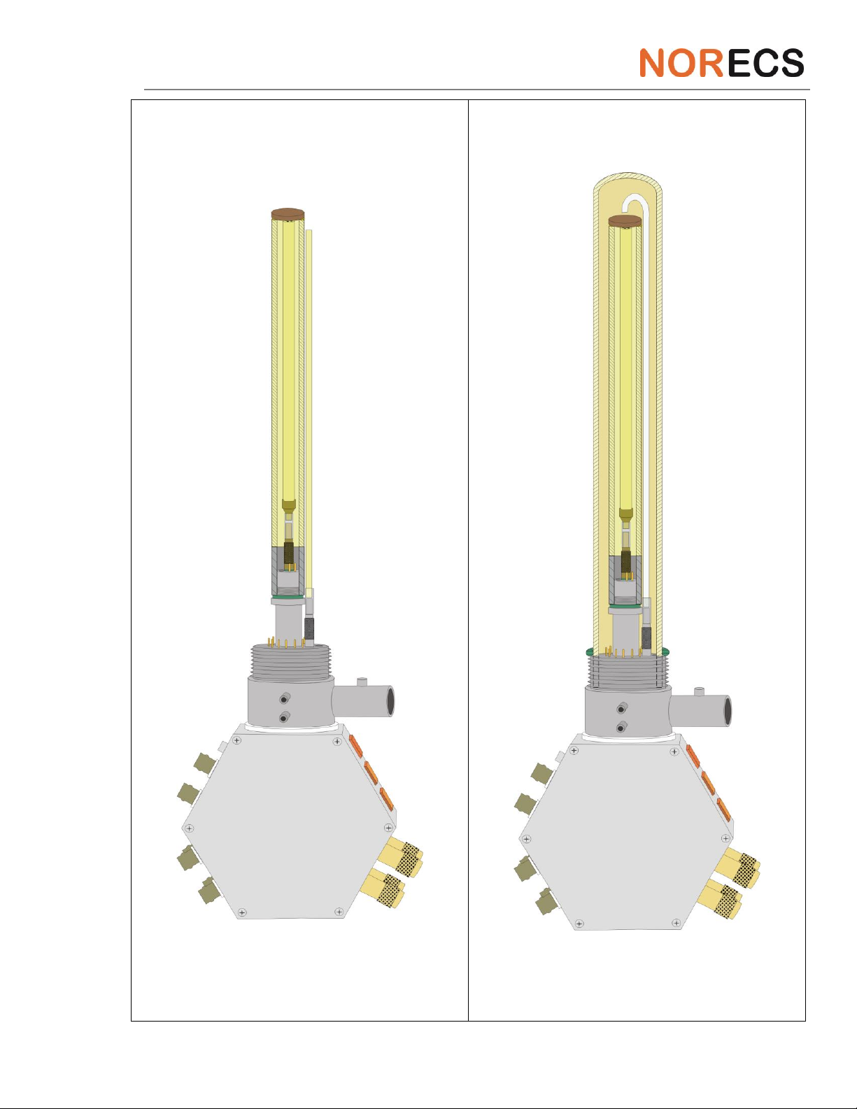
1.6. Setting up gas compartments
This part presents a step-by-step description how to create two ProboStat™gas compartments. For simplicity
only the gas supply system is shown. The electrical system, temperature control, spring-load system, and water
cooling system will be described elsewhere.

Complementary Material to ProboStat™ Manual
8
Table 5. Assembling ProboStat™ gas compartments.
Step 1:
Place the ProboStat base unit on the bench,
preferably fix it in a lab stand using a bar for base
unit fixture.
Step 2:
Mount the inner gas supply tube onto the PEEK gas
stub.

Complementary Material to ProboStat™ Manual
9
Step 3: Mount the sample support tube tight.
Step 4: Place an Au sealing ring on top of the
sample support tube. *
*This step is relevant for the gas compartments separation. If you plan to measure using the single
atmosphere mode, skip this step.

Complementary Material to ProboStat™ Manual
10
Step 5: Place a sample on top of the gold ring (or
directly on the sample support tube for the single
atmosphere mode). Check that the gold ring and
sample are centered.
Step 6: Mount outer bent silica (a) or straight
alumina (b) gas tube onto the SS gas stub.
a)
Complementary Material to ProboStat™ Manual
11
Step 6: Mount outer bent silica (a) or straight
alumina (b) gas tube onto the SS gas stub.
Step 7: Mount enclosing quartz or alumina tube
and O-ring.*
*For simplicity the spring load assembly is not
explained or drawn here. In real setup it is always
present and push the sample down on the AU ring.
b)

Complementary Material to ProboStat™ Manual
12
Step 8: Fasten the base unit flange.
Complementary Material to ProboStat™ Manual
13
2. ProboStat™ electrical system
In this part we describe ProboStat™ electrode contact assemblies, base unit electrical wiring, and coaxial
cables.
2.1. Recommended reading
We recommend familiarizing youself with:
a) ProboStat™ Manual:
Part 4.2.6 “Electrical feedthroughs”, pp. 4-7 –4-8,
Part 4.2.7 “Sockets and switches on the connector box”, pp. 4-8 –4-10,
Part 4.2.8 “Wiring Schemes”, pp. 4-10 –4-12,
Part 4.7 “Thermocouple and electrode contacts”, pp. 4-15 –4-19,
Part 6.4 “Electrical specification”, pp. 6-2 –6-3,
Part 7.1 “Electrical wires”, pp. 7-1,
Part 12.4 “Instruction for fabrication of electrode contact assemblies”, pp. 12-13 –12-20.
b) NorECs web page www.norecs.com :
FAQ –How can I repair a Pt electrode contact?
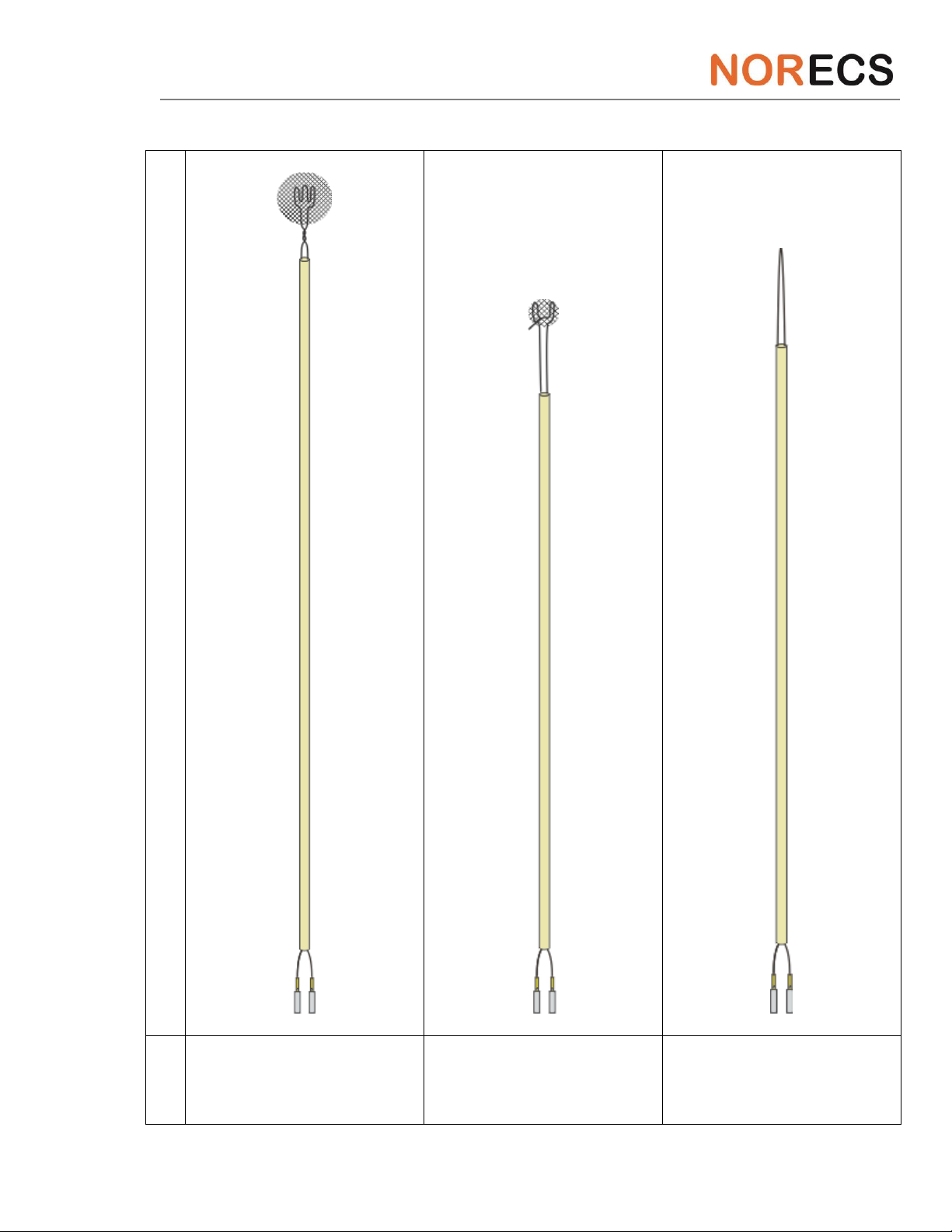
2.2. Electrode contact assemblies
Electrode contact assemblies (hereafter called electrode contacts) are assigned to contact the ProboStat™
base unit with a test sample located in the high-temperature zone.
2.2.1.
Description and denotation
The electrode contacts for electrical measurements come in variety of types. Many of them are issued in 2-
wire pairs; one for current and one for voltage.
Table 6. Electrode contacts denotation
Code
Description
H2N#
Electrode “hand” contact assembly, outer, 2-wire. # - diameter of Pt net disk
H1TN10
Electrode “hand” contact assembly, outer, 1-wire, top
H1BN10
Electrode “hand” contact assembly, outer, 1-wire, bottom
INH2N12
Electrode “hand” contact assembly, inner, 2-wire
IN2
Electrode contact assembly, inner, 2-wire
GP2
Electrode contact assembly, general purpose, 2-wire
GP1
Electrode contact assembly, general purpose, 1-wire
GR#
Guard ring. # - diameter of ring
vdP
Van der Pauw contact assembly
Complementary Material to ProboStat™ Manual
14
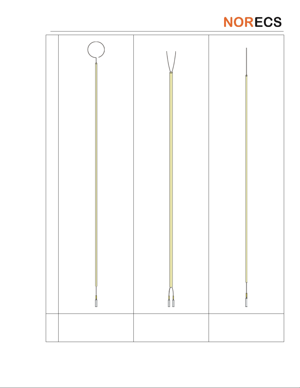
Tabel 7. ProboStat™ electrode contacts.
Electrode contact drawing
Code
H2N#
INH2N12
IN2
Complementary Material to ProboStat™ Manual
15
Electrode contact drawing
Code
GR#
GP2
GP1

Complementary Material to ProboStat™ Manual
16
Electrode contact drawing
Code
H1TN10
H1BN10
vdP2

Complementary Material to ProboStat™ Manual
17
2.2.2.
High-voltage electrode contacts
High-voltage (HV) electrode contacts are suitable for connection to special feedthroughs on the HV base
unit. The HV base units are made upon request and usually not a matter for the detailed description.
There are two types of HV electrode contacts:
Electrode “hand” contact assembly, outer, 1-wire, HV-version
(H1N10HV)
Guard ring, HV-version
(GR#HV)
HV electrode contacts are shorter than normal and soldered to bigger mini-contacts.
2.2.3.
Mini-contacts
Supplied electrode contacts and thermocouples (see below) are soldered to female mini-contacts matching
to the base unit feedthroughs. The mini-contacts are made of Au- and Ni-plated brass, and have size
22AWG, HV version –20AWG.
2.2.4.
Soldering of mini-contacts
When soldering insert an appropriate metal wire into the mini-contact, and add solder by tiny portions until
the mini-contact cup is filled. A solder drop should be visible through a small hole into the mini-contact.
Make “shoulders” by pulling out the solder. It is important that solder wets metals.
Correct. The surfaces are wetted.
Wrong. The surfaces are non-wetted.
Fig. 9. Soldering of mini-contacts.

Complementary Material to ProboStat™ Manual
18
2.2.5.
Mounting electrode contacts on the base unit.
In order to connect the electrode contact to the base unit, mount the mini-contacts carefully onto
appropriate feedthroughs. You may use a tweezers.
Fig. 10. The electrode contact connected to the base unit.
2.3. Base unit wiring
2.3.1.
Wiring overview
The Wiring Overview (see next page, example for K-wired base unit) shows the coordinates, numbering
and standard material of the electrical wiring for the base unit feedthroughs (top view, in relation to the
gas inlets (I) and outlets (O)). Also the Phoenix-type chassis multi-connector that was fitted to early
version is shown. The coding and functions are listed in detail in the table below.
We strongly recommend users to print the Wiring Overview (page 14-2 or 14-3 in the ProboStat™ manual)
and hang it on a wall next to the ProboStat™ assembling point.
2.3.2.
Phoenix-type multi-connector
The Phoenix type of multi-connector (Fig. 10) is no longer in use, and will not be described here. In case
you need more information, please contact us.

Complementary Material to ProboStat™ Manual
19
Wiring overview (all figures are top views)/K-Type
Standard electrical wiring of ProboStat versions A-2 and later, using S-type thermocouples.
Base unit feed-through
code
Base unit
feedthrough colour
code
Standard
material
in hot zone
Function
Function code
Phoenix rectangular
multi-connector
(optional) code
BNC code
(S = shield)
Thermocouple contact
codes
1 P
Green
NiCr
Bottom/inner TC+
TCB+
-
-
TCB+
2 N
White
NiAl
Bottom/inner TC-
TCB-
-
-
TCB-
3 G
-
Pt
Inner low current
ILC
a
ILC
-
4 G
-
Pt
Inner low voltage
ILV
c
ILV
-
5 G
-
Pt
Low current shield
LCS
i,j
LCS
-
6 G
-
Pt
Low current/Guard
LC
b
LC
-
7 G
-
Pt
Low voltage shield
LVS
k,l
LVS
-
8 G
-
Pt
Low voltage
LV
d
LV
-
9 P
Green
NiCr
Top TC+
TCT+
-
-
TCT+
10 N
White
NiAl
Top TC-
TCT-
-
-
TCT-
11 P
Green
NiCr
Centre/control TC+
TCC+
-
-
TCC+
12 N
White
NiAl
Centre/control TC-
TCC-
-
-
TCC-
13 G
-
Pt
High voltage
HV
g
HV
-
14 G
-
Pt
High voltage shield
HVS
o
HVS
-
15 G
-
Pt
High current
HC
h
HC
-
16 G
-
Pt
High current shield
HCS
p
HCS
-
Switches: Ch+HCS: Chassis to shield (HCS), LC+HCS: Guard (LC) to shield (HCS), when DOWN.
Shields Br.: Connects all four shields together when DOWN.
The base unit shown here is for A-
3 and higher. For A-2/A-1/B the
outer In and Out gas paths (on the
outer circle) are swapped.

Complementary Material to ProboStat™ Manual
20
Fig. 10. Phoenix-type multi-connector wiring overview.
2.3.3.
Overview of base unit electrical feedthroughs
By electrical feedthrough we mean an assembly where the electrical lead goes through the base unit
chassis from the electrode contacts to BNC contacts mounted on the base unit hexagon. The electrical
feedthrough consists of male mini-contact, sitting in PEEK insulator, and soldered to compensation wire.
The feedthroughs are numbered starting with very top of the base unit and run clockwise from 1 to 4. The
numbering continues on the outer ring from 5 to 16 again clockwise. The feedthroughs no. 1-4 are located
in the inner gas compartment, no. 5-16 –in the outer.
Fig. 11. Feedthrough numbering:
drawing.
Fig. 12. Feedthrough numbering on
base unit.
Fig. 13. Electrical feedthroughs
codes

Complementary Material to ProboStat™ Manual
21
The feedthrough codes, standard materials and functionality are presented in the bottom table of the
Wiring Overview.
2.3.4.
Feedthroughs colour code
The base unit has 16 feedthroughs: 10 electrical and 6 for thermocouples. All feedthroughs are colour
coded.
Table 8. Feedthrough colour code
Colour
Compensation wire to
Function
Red
Pt
Electrical, general
S-type thermocouple, negative
Black
Pt10%Rh
S-type thermocouple, positive
White
NiAl
K-type thermocouple, negative
Green
NiCr
K-type thermocouple, positive
2.3.5.
Signal and shield feedthroughs
The ProboStat™ base unit has 10 electrical feedthroughs, 6 of them lead current or voltage signal, 4 -
shield. The signal feedthroughs are soldered to the center of the BNC contacts, shields –to the plates.
ILC and ILV feedthroughs do not have own shield feedthroughs. However shield is important for some
measurement instruments. For this reason, shield plates of LC and ILC, LV and ILV BNC contacts are
connected pairwise. LCS and LVS act as shields for both, inner and outer, current and voltage probes.
Fig. 14. Signal and shield connection from inside of
the base unit.
Fig. 15. Signal and shield connection from outside
of the base unit.
Other manuals for ProboStat
1
Table of contents


