Norecs ProboStat Instructions and recipes
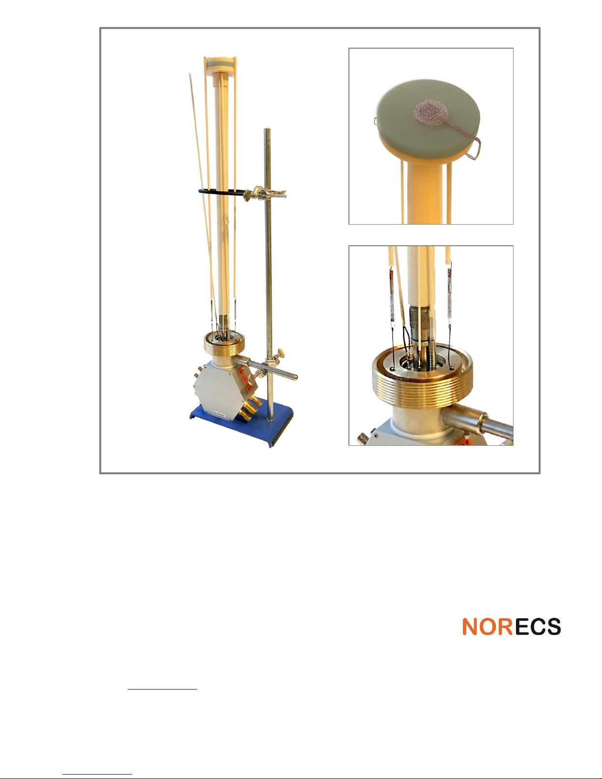
Large Sample Setup for ProboStat™
Supplementary Material to the ProboStat™ Manual
Update: October 31, 2018
Copying allowed for internal use within organization or buyer of the product.
NORECS AS
Gaustadalléen 21
NO-0349 Oslo, Norway
Tel.: +47 45916188
E-mail: [email protected]
Web: www.norecs.com

Supplementary Material to ProboStat™ Manual
2
This is a supplement to the ProboStat™ manual, to be used together with (and not instead of) the manual.
1. Introduction
The large sample setup for ProboStat™ has been developed to accomplish the following:
measurements on disk samples with diameter up to 60 mm,
full compatibility with the standard ProboStat™ base unit,
controlled atmospheres or low vacuum, temperature range RT - 1600°C.
The setup is operating in the single atmosphere mode and can be used for:
2-point impedance spectroscopy and conductivity measurements on large disk samples vs T, pO2, pH2O, etc.
2-point conductivity measurements with surface guard,
electrode impedance studies with ring reference electrode,
voltammetry studies with ring reference electrode.
For detailed methods description please see the ProboStat™ Manual (www.norecs.com).
The setup utilizes adapter that allows standard ProboStat™ to mount 80 mm enclosing tube (with 70 mm inner
diameter).
Important:
The large sample enclosing tube makes the setup top heavy, and the normal stand system is inadequate to be used in
the traditional fashion. The large sample set includes additional way of supporting and stabilizing the ProboStat cell.
The blue base should be attached to the bottom of the ProboStat using the supplied screws. Open the side plate of the
ProboStat base unit, add and tighten the screws and nuts (use the washers) as illustrated in the Figure below.
Supplementary Material to ProboStat™ Manual
3
2. Contents and assembly
2.1. Contents
One set of neck adapter and flange made of brass,
One alumina enclosing tube with outer diameter 80 mm, closed one end,
One enclosing quartz/metal ring with outer diameter 40 mm used to avoid gas leakage through the adapter,
One standard ProboStat™ sample support tube assembly with outer diameter 24 mm,
One alumina support plate / sample support tube adapter for sample stabilization and resting of the ring
electrode contact,
One spring load assembly consisting of one alumina support plate with central hole, three standard long
alumina bars with holes, one top triangle made of Pt10%Rh wire Ø 1 mm, and three soft springs,
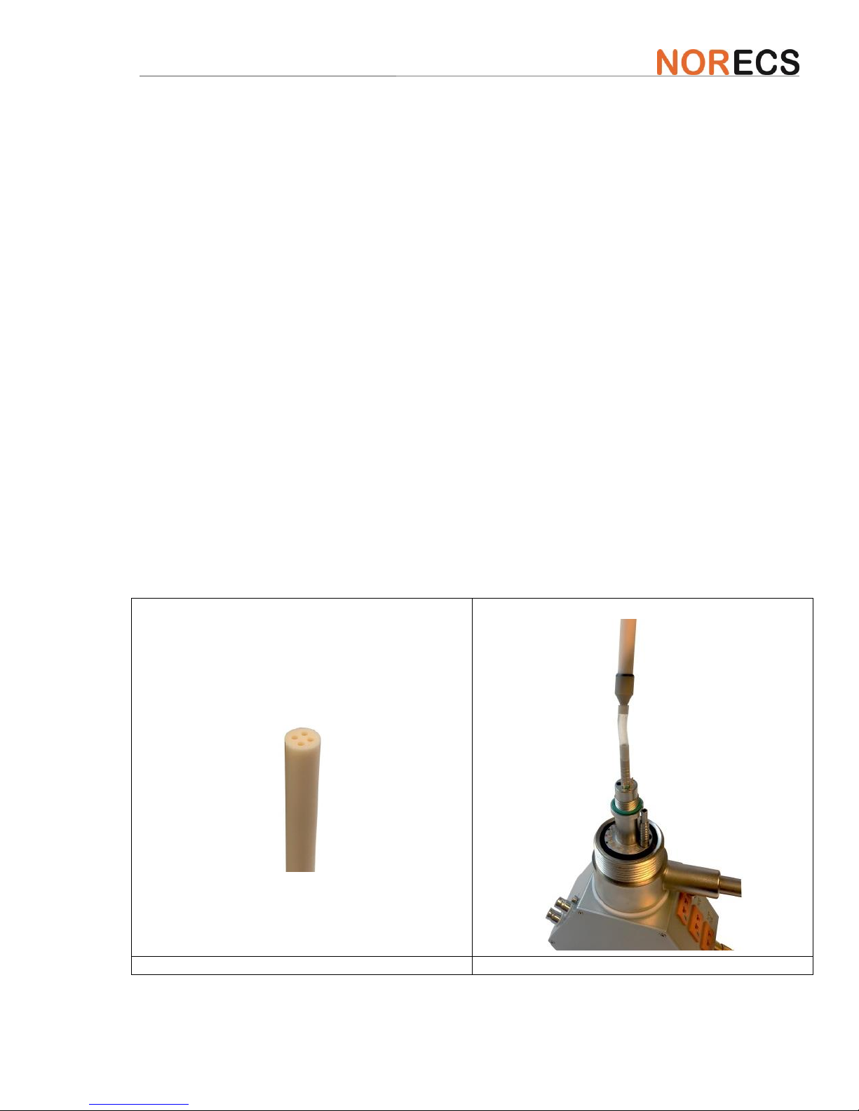
One standard alumina inner multi-bore gas supply tube with 3.9 mm length silicone hose,
One standard outer alumina gas supply tube,
One thermocouple for disk sample, S-type, alumina,
One Pt/alumina guard-reference-ring electrode with 58 mm Ø ring.
One Pt/alumina inner “hand” electrode contact,
One Pt/alumina outer “hand” electrode contact with 20 mm Ø net,
One Pt net, Ø 20 mm,
Two Viton O-rings, 80×3 mm and standard 40×3 mm.
2.2. Assembly
The given example is related to Part 8.2.3 in the ProboStat™ manual: 2-point conductivity measurements on disk
sample with surface guard. For other methods please refer to the corresponding chapter in the ProboStat™ manual.
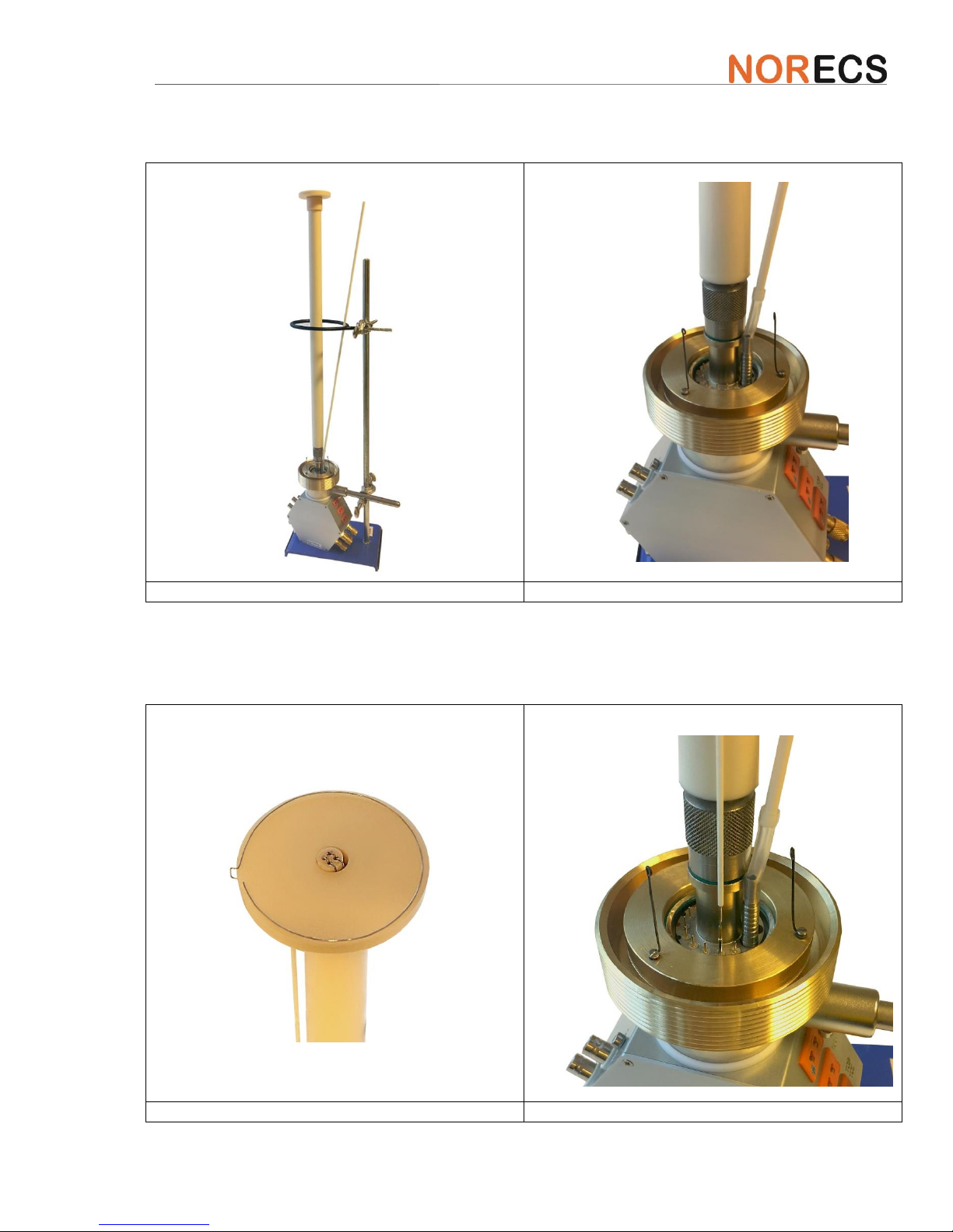
Step 1: Mount the multi-bore gas tube onto the inner PEEK gas socket.
High temperature zone
Connections to the ProboStat™ base unit

Supplementary Material to ProboStat™ Manual
4
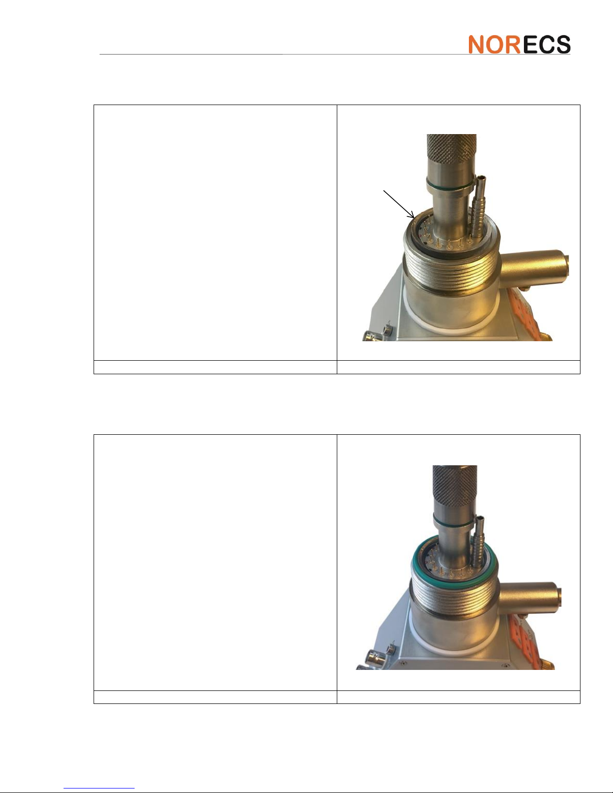
Step 2: Mount the inner “hand” electrode contact onto ILC and ILV feedthroughs, no. 3 and 4 accordingly.
Carefully insert the top part of the electrode contact down into the multi-bore tube.
High temperature zone
Connections to the ProboStat™ base unit
Step 3: Mount the sample support tube. Adjust the height of the gas tube so that the electrode contact touches
sample when the support plate / support tube adapter is mounted (see Step 7). Take the adapter off.
High temperature zone
Connections to the ProboStat™ base unit
Supplementary Material to ProboStat™ Manual
5
Step 4: Insert the enclosing quartz/metal ring in the base unit groove for the enclosing tube.
High temperature zone
Connections to the ProboStat™ base unit
Step 5: Place the standard Viton O-ring (40×3 mm) outside the quartz ring.
High temperature zone
Connections to the ProboStat™ base unit
quartz ring
Supplementary Material to ProboStat™ Manual
6
Step 6: Mount the neck adapter.
High temperature zone
Connections to the ProboStat™ base unit
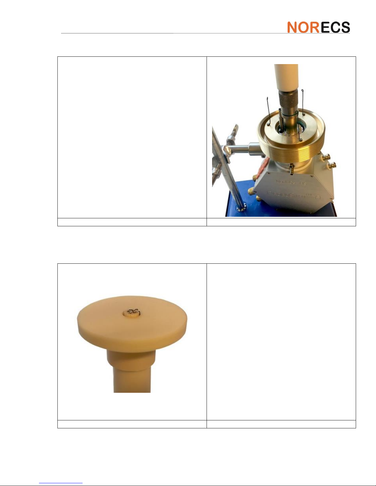
Step 7: Place the support plate / sample support tube adapter on top of the support tube. The gas supply tube
should be approximately 1 mm above the adapter.
High temperature zone
Connections to the ProboStat™ base unit
Supplementary Material to ProboStat™ Manual
7
Step 8: Mount the outer gas supply tube onto the outer steel gas socket. Be careful when mounting. We
recommend using the stand ring for support during mounting.
General view
Connections to the ProboStat™ base unit
Step 9: Insert the ring electrode contact onto LC feedthrough (no. 6). Carefully bend the top part of the
electrode contact so that it covers the rim of the alumina plate.
High temperature zone
Connections to the ProboStat™ base unit

Supplementary Material to ProboStat™ Manual
8
Step 10:Place the 20 mm Ø platinum net on top of the inner “hand” electrode contact.
High temperature zone
Connections to the ProboStat™ base unit
Step 11:Insert the control thermocouple onto feedthroughs no. 9 and 10, or no. 11 and 12. Mind the
polarity!
General view
Connections to the ProboStat™ base unit

Supplementary Material to ProboStat™ Manual
9
Step 12:Place the sample so that it rests on the support plate. Make sure that it slightly presses down
the the inner “hand” electrode contact, and the ring electrode contact is in the correct position.
High temperature zone
Connections to the ProboStat™ base unit
Step 13:Insert the outer “hand” electrode contact onto HV and HC feedthroughs, no. 13 and 15 accordingly.
Carefully bend the top part of the electrode contact.
High temperature zone
Connections to the ProboStat™ base unit
Supplementary Material to ProboStat™ Manual
10
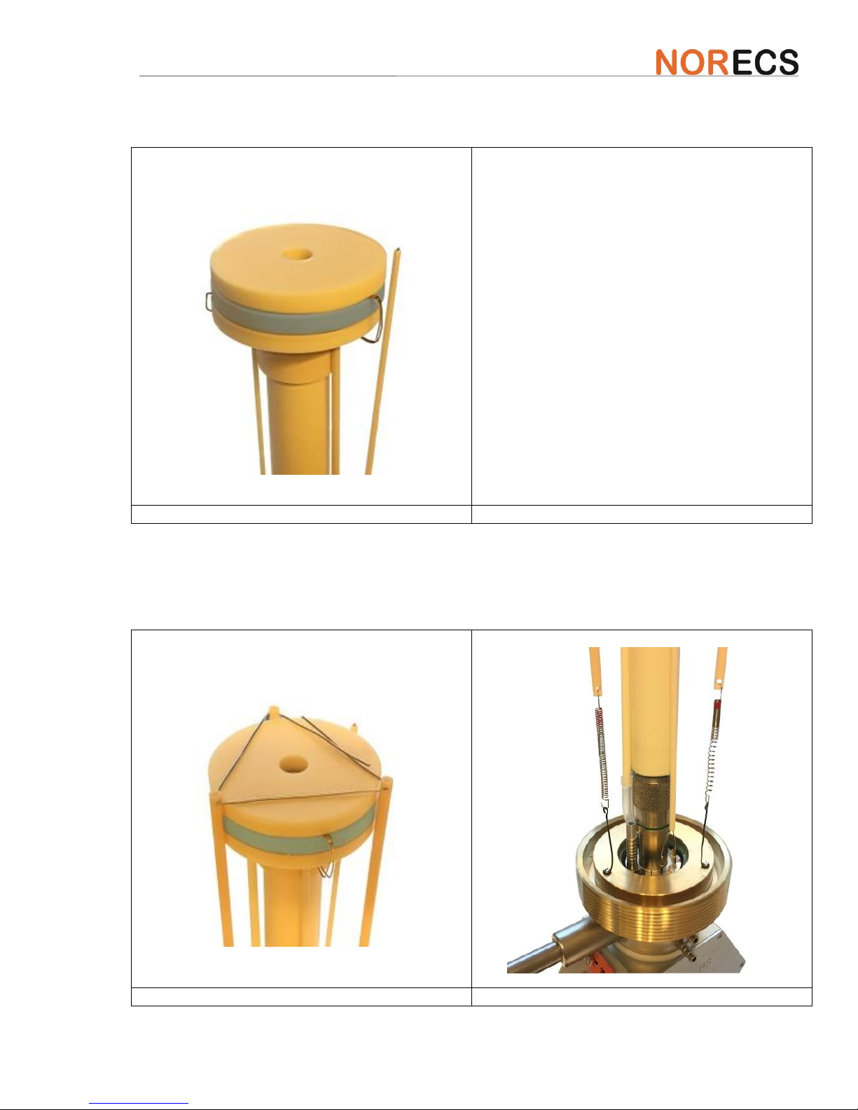
Step 14:Place the support plate with central hole on the outer electrode contact.
High temperature zone
Connections to the ProboStat™ base unit
Step 15: Position the pre-mounted spring load tubes into the triangle vertexes. Place the assembly on top of the
support plate. Hook the springs onto the lower part of the spring load tubes. Hook the springs over the
neck adapter. Hold firmly the top part in place while connecting.
High temperature zone
Connections to the ProboStat™ base unit

Supplementary Material to ProboStat™ Manual
11
At this point the setup is assembled. There are two methods to close it with the enclosing tube.
Alternative one:
Step 16: Place the O-ring on the neck adapter and screw on the flange all way down. Do not tighten.
Connections to the ProboStat™ base unit
Connections to the ProboStat™ base unit
Step 17:Insert the enclosing tube into the flange. You should be sure that the tube reaches the bottom of the
base unit groove. Do not drop it! Afterwards tighten the flange.
General view

Supplementary Material to ProboStat™ Manual
12
Alternative two:
Steps 16: Mount the O-ring onto the open end of the enclosing tube. Insert the tube into the base unit groove.
Move the O-ring down.
General view
Connections to the ProboStat™ base unit
Step 17:Carefully move the flange down the enclosing tube. Do not tilt it as it can become jammed! Tighten the
flange.
General view
Step 18: Make electrical and gas connections (please see the ProboStat™ Manual, Chapter 8).

Supplementary Material to ProboStat™ Manual
13
The ProboStat™ manual can be downloaded from the NORECS website www.norecs.com.
For more information please contact us:
NORECS AS
Gaustadalléen 21
NO-0349 Oslo, Norway
Tel.: +47 45916188
E-mail: [email protected]
Web: www.norecs.com
Other manuals for ProboStat
1
Other Norecs Laboratory Equipment manuals

Popular Laboratory Equipment manuals by other brands

MELAG
MELAG Cliniclave 45 user manual

Evertree
Evertree Liva EBS Series user manual

Thermo Scientific
Thermo Scientific ProPac SCX-20 product manual

Thermo Scientific
Thermo Scientific 2870 Operating and maintenance manual

MRC
MRC DFO-720 Operation manual

BioNano Genomics
BioNano Genomics Saphyr System Setup guide


