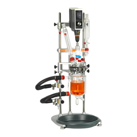
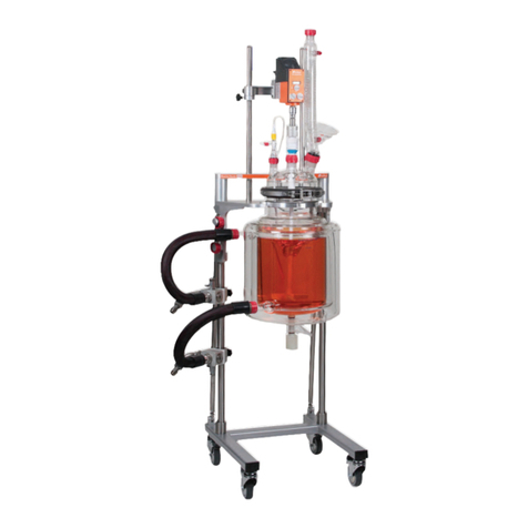
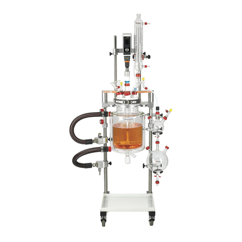
Radleys Reactor-Ready User manual

Instructions
Reactor-Ready™
ab Reactor
Patent Pending
Your Local Distributor
August 2009 Issue 3
Radleys, Shire Hill, Saffron Walden, Essex, CB11 3AZ. United Kingdom.
Tel: +44-(0)1799-513320 Fax: +44-(0)1799-513283
Email: sales@radleys.co.uk Web: www.radleys.co.uk
innovations for chemistry

Page 1
Reactor-Ready - Lab Reactor
Index
Page 1 Index
Page 2 1. Introduction
2. Warranty
Page 3 3. Safety Information
4. Important WARNINGS
Page 4 5. Products & Accessories
Page 5 6. Component Guide
Page 6 7. Quick Start Guide
Page 7 7. Quick Start Guide - Continued
Page 8 8. Set-Up & Operation - Continued
8.1 Optimising the thermal performance of Reactor-Ready
8.2 Operating temperature range
8.3 Setting up Reactor-Ready
Page 9 8. Set-Up & Operation - Continued
8.4 Assembling the Manifolds
Page 10 8. Set-Up & Operation - Continued
8.5 Locating the support braces
Page 11 8. Set-Up & Operation - Continued
8.6 Preparing the reaction vessel
Page 12 8. Set-Up & Operation - Continued
8.7 Assembling the vessel lid, stirrer guide and probe
Page 13 8. Set-Up & Operation - Continued
8.8 Assembling the thermofluid hoses
8.9 Assembling the Overhead Stirrer
Page 14 8. Set-Up & Operation - Continued
8.10 Choosing your thermoregulator (recirculator)
8.11 Choosing your thermofluid
Page 15 8. Set-Up & Operation - Continued
8.12 Connecting the thermoregulator
8.13 If adapters and isolating valves are not to be used
8.14 If adapters and isolating valves are to be used
8.15 Charging Reactor-Ready with thermofluid
Page 16 8. Set-Up & Operation - Continued
8.16 Draining thermofluid from Reactor-Ready
8.17 Disconnecting the thermoregulator
Page 17 9. General Specifications
10. Routine Maintenance
Page 18 11. General Information
11.1 Materials of Construction
11.2 Vacuum & Pressure
11.3 Use of zero dead space stopcock
11.4 Safe Delta T (ΔT)
Page 19 WARRANTY - FAX BACK

Reactor-Ready - Lab Reactor
Thank you for purchasing your Reactor-Ready.
Please read this Instruction Manual thoroughly before operating your unit.
1. Introduction
Reactor-Ready is a flexible benchtop reaction system incorporating a host of features around a purpose built framework,
which can be used with a wide range of dedicated glass reaction vessels and accessories. Additional attachment of a thermoregulator
allows a fully comprehensive range of heating and cooling operations to be performed.
Features include...
• Rapid vessel exchange with quick-release vessel clamp and hose couplings.
• Range of single and double jacketed glass vessels including 250ml, 500ml, 1 litre, 2 litre and 5 litre.
• Support system accepts all leading brands of overhead stirrer and allows easy, tool free adjustment.
• Triple support stand features heavy duty stainless steel support rods for maximum strength and stability.
• Self aligning stirrer coupling engages without the need for tools.
• Hose manifolds allow easy thermofluid drain down.
• Temperature range: -60ºC to +190ºC (subject to thermoregulator).
• Wide range of accessory glassware including condensers, dropping funnels etc.
2. Warranty
Reactor-Ready includes one year full parts and labour warranty from date of original purchase.
Warranty will only be valid if a completed Warranty Fax Back is returned within 1 month of date of purchase (see last page).
In the event of product failure please contact your local distributor. Please do not return any goods without prior agreement.
Page 2

Reactor-Ready - Lab Reactor
3. Safety Information
The following symbols are intended to assist the user in the safe and efficient operation of Reactor-Ready.
4. Important WARNINGS
• Please read these instructions completely before using your Reactor-Ready system.
• Always read the instructions of any third party equipment, such as overhead stirrers and thermoregulators thoroughly
to ensure you are not contravening any safety recommendations or manufacturers warranty when used
in conjunction with Reactor-Ready.
• Always ensure that the Reactor-Ready vessel is clamped and supported correctly, using the purpose built stand
and clamp. Under no circumstances should the system be operated without this stand.
• The maximum operating speed for Reactor-Ready is 500rpm for continuous operation and 800rpm for short periods.
• It is the responsibility of the user to ensure correct set up, and continued maintenance of the stand, clamps and framework.
• Always ensure that Reactor-Ready is located on a level surface.
• Operate only in a fumehood with protective safety sash.
• Risk of burns from hot or extreme cold during and after heating/cooling, therefore take care not to touch
the Reactor-Ready unit, or any of the auxiliary modules.
• Reactor-Ready unit will remain hot for some considerable time after the heating source has been switched off.
A temperature probe or temperature sensitive label can be used to indicate when components are too hot to touch.
• Before starting your reaction, ensure that all fittings to the thermoregulator are fully tightened and not leaking
and that the manifold drain and vent valves are closed.
• Reactor-Ready metal components are resistant to the majority of solvents and splash resistant
to dilute acids and alkalis at room temperature.
• Always wipe away any chemical spills immediately and avoid exposure to strong vapours such as HC etc,
as continued exposure to chemical vapours or liquids will cause corrosion to metal and/or plastic components.
• Reactor-Ready can be used with a recirculating fluid at a temperature of up to 190˚C, or down to -60°C without
damage to the unit. Careful inspection of all fluid connections to Reactor-Ready should be regularly performed when
operating at these temperatures.
• Ensure all wires and cables connecting auxiliary equipment are secured such that they cannot come into
contact with Reactor Ready surfaces, or moving parts.
• Reactor-Ready should only be operated by trained and competent personnel. As with all chemistries, a full risk
assessment should be performed prior to starting, and care should be taken to monitor your reactions at all stages.
During operation Reactor-Ready should not be left unattended unless in a supervised area.
Page 3
Warning
Applies when there is a possibility
of personal injury.
Important Note
Alerts the user to important facts.
!
Important, Important,

Page 4
Reactor-Ready - Lab Reactor
5. Products & Accessories
How to order Reactor-Ready…
1. Select the Reactor-Ready Core: RR121000
2. Select the vessel size and whether you want single or double/vacuum
jacketed, then select the Vessel Kit you need
3. Select your overhead stirrer
4. If you need a thermoregulator/circulator, hoses, hose adapters, thermofluid
or accessory glassware like condensers or dropping funnels, then select
from the accessory list overleaf
5. Place your Purchase Order
Reactor-Ready Core System
RR121000 Reactor-Ready Core System. Includes:
•Stand with base, drip tray, support rods, bosses and all clamps
•Vessel to framework insulated hoses with quick-release connections
•Upper & lower drain-down manifolds
•PTFE Stirrer guide and coupling
•Glass reaction vessel lid with sealing caps
•Vessel FEP o-ring seal and PTFE centering collar
•Two stainless steel vessel support collars
Important: Hoses to connect the Reactor-Ready framework to your thermoregulator are
NO included. You will require hoses with a M24 connection or appropriate adapters.
See accessory list below for hoses, adapters and suitable thermoregulators.
Reaction Vessel Kits
These cost effective kits include all you need to get started; glass reaction vessel,
PTFE anchor stirrer paddle, PTFE PT100 temp probe (with Lemo plug for connection
to thermoregulator) and PTFE temperature probe adapter.
RR120010 250ml Single acketed Vessel Kit
RR120015 250ml Vacuum acketed Vessel Kit
RR120020 500ml Single acketed Vessel Kit
RR120025 500ml Vacuum acketed Vessel Kit
RR120030 1000ml Single acketed Vessel Kit
RR120035 1000ml Vacuum acketed Vessel Kit
RR120040 2000ml Single acketed Vessel Kit
RR120045 2000ml Vacuum acketed Vessel Kit
RR120050 5000ml Single acketed Vessel Kit
RR120055 5000ml Vacuum acketed Vessel Kit
Overhead Stirrers
501-20200-00 Heidolph Stirrer RZR 2020
501-20410-00 Heidolph Stirrer RZR 2041
501-20521-00 Heidolph Stirrer RZR 2052 Control
Thermoregulators, Hoses, Adapters & Thermofluids…
Important: For technical advice on selecting the thermoregulator, thermofluid or hoses
for your application please contact our technical sales team on el: +44(0)1799-513320
or E-mail: sales@radleys.co.uk
Huber Thermoregulators/Circulators
HB201501.04 Ministat 230-CC
HB103001.04 Petite Fleur
HB100001.05 Unistat Tango
HB100203.05 Unistat 405
HB100102.05 Unistat 705
Thermoregulator Hoses & Adapters
HB9274 M24x1.5 Insulated Hose NW12 100cm
HB9275 M24x1.5 Insulated Hose NW12 150cm
HB9276 M24x1.5 Insulated Hose NW12 200cm
HB9277 M24x1.5 Insulated Hose NW12 300cm
HB6724 M24x1.5 Female to M16x1 Male Adapter
HB6945 M24x1.5 Male to M16x1 Female Adapter
HB6723 M24x1.5 Female to M30x1.5 Male Adapter
HB6195 M16x1 90 degree Adapter
HB9256 M24x1.5 90 degree Adapter
HB6089 M16x1 Nut
HB12634 M24x1.5 Nut
HB6086 M16x1 Hose Connector NW8
HB9471 M24x1.5 Hose Connector NW12
HB6091 M16x1 Isolating Ball Valve
HB9236 M24x1 Isolating Ball Valve
Thermofluid
HB6159 SynOil M10.155.08, 5 Litre Range -10 to +155°C
HB6160 SynOil M10.155.08, 10 Litre Range -10 to +155°C
HB6161 SilOil M20.235.20, 5 Litre Range -20 to +235°C
HB6162 SilOil M20.235.20, 10 Litre Range -20 to +235°C
HB6163 SilOil M40.165.10, 5 Litre Range -40 to +165°C
HB6164 SilOil M40.165.10, 10 Litre Range -40 to +165°C
HB6165 SilOil M60.115.05, 5 Litre Range -60 to +115°C
HB6166 SilOil M60.115.05, 10 Litre Range -60 to +115°C
HB6479 DW-Therm M90.200.02, 10 Litre Range -90°C to +200°C
Optional Accessories & Replacement Parts…
Reaction Vessels Only
RR130250 250ml Single acketed Vessel
RR130255 250ml Vacuum acketed Vessel
RR130500 500ml Single acketed Vessel
RR130550 500ml Vacuum acketed Vessel
RR131000 1000ml Single acketed Vessel
RR131050 1000ml Vacuum acketed Vessel
RR132000 2000ml Single acketed Vessel
RR132050 2000ml Vacuum acketed Vessel
RR135000 5000ml Single acketed Vessel
RR135050 5000ml Vacuum acketed Vessel
Reaction Vessel Lid
RR136000 5 Neck Lid - 1 x B19, 2 x B24, 1 x B29, 1 x B34
Reaction Vessel Support Collar
RR121048 Vessel Support Collar
Important: he support collar is needed for your Reactor-Ready vessel to fit in the novel
quick-release clamp. wo collars are supplied with the Reactor-Ready Core System
(RR121000), if you require more for additional vessels see details below:
PTFE Pt100 Temperature Probes & Adapters
RR140250 Probe 8mm with Lemo Plug - 250ml & 500ml vessels
RR141000 Probe 9mm with Lemo Plug - 1000ml & 2000ml vessels
RR145000 Probe 9mm with Lemo Plug - 5000ml vessel
RR140010 PTFE Temperature Probe Adapter - 8mm
RR140015 PTFE Temperature Probe Adapter - 9mm
PTFE Stirrer Shafts
RR150250 Anchor PTFE Stirrer Shaft - 250ml vessels
RR150255 Retreat Curve PTFE Stirrer Shaft - 250ml vessels
RR150260 Turbine PTFE Stirrer Shaft - 250ml vessels
RR150500 Anchor PTFE Stirrer Shaft - 500ml vessels
RR150505 Retreat Curve PTFE Stirrer Shaft - 500ml vessels
RR150510 Turbine PTFE Stirrer Shaft - 500ml vessels
RR151000 Anchor PTFE Stirrer Shaft - 1000ml vessels
RR151005 Retreat Curve PTFE Stirrer Shaft - 1000ml vessels
RR151010 Turbine PTFE Stirrer Shaft - 1000ml vessels
RR152000 Anchor PTFE Stirrer Shaft - 2000ml vessels
RR152005 Retreat Curve PTFE Stirrer Shaft - 2000ml vessels
RR152010 Turbine PTFE Stirrer Shaft - 2000ml vessels
RR155000 Anchor PTFE Stirrer Shaft - 5000ml vessels
RR155005 Retreat Curve PTFE Stirrer Shaft - 5000ml vessels
RR155010 Turbine PTFE Stirrer Shaft - 5000ml vessels
Glassware Accessories
RR139005 Condenser Liebig 250mm B29 + GL14 + fittings
RR139007 Condenser Double Surface 200mm B29 + GL14 + fittings
RR139009 Condenser acket Coil Rodaviss B29 + GL14 + fittings
RR139011 Right Angle Adapter B29 + GL14 + PTFE fittings
RR139013 50ml Graduated Dropping Funnel Equalising Arm B24
RR139015 100ml Graduated Dropping Funnel Equalising Arm B24
RR139017 250ml Graduated Dropping Funnel Equalising Arm B24
RR139019 500ml Graduated Dropping Funnel Equalising Arm B24
RR139021 1000ml Graduated Dropping Funnel Equalising Arm B24
RR139023 Swan Neck Adapter B24 to B24
RR139025 Gas Purge Adapter B24 + GL14 + fittings
RR139027 Glass Cone Stopper B19
RR139029 Glass Cone Stopper B24
RR139031 Glass Cone Stopper B29
RR139033 Glass Cone Stopper B34
RR139035 Enlarging Adapter B24 to B29
RR139037 Enlarging Adapter B29 to B34
RR139039 Reducing Adapter B24 to B19
RR139041 Reducing Adapter B29 to B19
RR139043 Reducing Adapter B29 to B24
RR139045 Reducing Adapter B34 to B19
RR139047 Reducing Adapter B34 to B24
RR139049 Reducing Adapter B34 to B29
RR139051 Oil Bubbler Type 1 B24 + GL14 + fittings
RR139053 Solid Additions Funnel B34 (with extended tube)
RR139055 Liquid Additions Tubing Adapter B24 to GL14
RR139057 Valved Liquid Inlet Adapter B24 to GL14
RR139059 Reflux Divider Head B29
RR139061 Reflux Divider Head Receiver Bend
RR139063 PTFE Hose Adapter B19 for NW12 Tubing
RR139065 PTFE Hose Adapter B24 to 15mm Bore
RR139067 Boss Head
RR139069 3-Prong Clamp
US A Length Joints: For US ‘A Length’ glass cones and sockets please add a suffix /US to
the catalogue number when placing your order
Reactor-Ready - Lab Reactor
6. Component Guide
Page 5
1
3
5
6
7
8
8
9
12
13
14 16 19
18
15
17
4
10
11
Reactor-Ready Core System
1. Adjustable Feet
2. HDPE Drip Tray
3. Aluminium Base
4. Support Rod Bosses
5. Support Rods
6. Inlet Manifold
7. Outlet Manifold
8. Safety Stop Collars
9. Vessel Support Clamp
10. T-Beam Support Brace
11. Stirrer Support I-Brace
(with sliding boss)
12. Quick Release Insulated hoses
13. Rodaviss hose sealing caps
14. Vessel Support Collars
15. Glass Lid with Sealing Caps
16. PTFE Stirrer Guide
17. Locking Rod for Support Rod Bosses
18. Stirrer Drive Coupling
19. O-ring Seal and PTFE
Support Collar
2
A
E
B
D
C
Reaction Vessel kits
A. Glass Reaction Vessel with PTFE Stopcock
B. PTFE Anchor Stirrer
C. Sidearm Couplings (Connecting cap and connecting clip)
D. Pt100 PTFE Temperature Probe
E. PTFE Temperature Probe Adapter

Reactor-Ready - Lab Reactor
7. Quick Start Guide
Page 6
7.1 7.2
7.3
7.4
7.5
7.7
7.8
7.1 Identify a clear unobstructed site within your
fumehood near two suitable power outlets. You
will require a power supply for your thermoregula-
tor and for your overhead stirrer. Reactor-Ready
should not be moved after assembly so take care
to locate it in its final position. Position the base on
a flat surface. Adjust the feet by screwing in or out,
to ensure the base is level and stable. Locate the
Drip Tray into the base.
7.2 Screw 2 x Side (long) and 1 x Central (short)
Support Rods into the base - do not tighten the
Support Rod Bosses (locking knobs) at this stage.
Important Note - Once support
rods are assembled in the base,
they should be wiped evenly with a
lubricating cloth (enclosed) to aid
further assembly of components.
7.3 Slide the T-Beam Support Brace onto the
framework and down to the bottom of the rods.
Now tighten the Support Rod Bosses on the rods
using the tool provided. Then remove the T-Beam
Support Brace from the framework.
7.4 Firstly slide down the Inlet (lower) and Outlet
(upper) Manifolds onto the left hand support rod.
Then slide down the Vessel Support Clamp, then
the T-Beam Support Brace and finally the Stirrer
Support I-Brace. Ensure that Safety Stop Collars
are positioned below both the Vessel Support
Clamp and Stirrer Support I-Brace before they are
slid into position. Take care to add the compo-
nents in the order required. Hand tighten all knobs
securely.
7.5 Assemble the vessel support collar onto the
vessel neck, and tighten.
IMPORTANT NOTE - Correct align-
ment of the vessel support collar is
essential for smooth operation of
the clamp. For further details see
section 8.6.
7.6 Position the glass reactor on the Vessel Clamp.
7.7 Assemble the Vessel O-ring Seal and PTFE
Support Collar and place onto the vessel neck
flange.
7.8 Position the Stirrer Guide in the central lid port
and hand tighten the red (Rodaviss) screw cap fit-
ting to secure. Slide the stirrer shaft into the Stirrer
Guide so that the top just protrudes from the recess
of the aluminium stirrer guide cap and tighten the
cap to lock the shaft in place.
7.6
Important, Important,
7.4

Reactor-Ready - Lab Reactor
7. Quick Start Guide
7.12 7.14
7.14
7.13
7.15
7.9 Position the lid onto the O-ring Seal (on the
vessel flange), close the clamp jaws and lock with
the fastening clip.
7.10 Attach the Insulated Hoses to the lower Inlet
Draindown Manifold and upper Outlet Manifold by
screwing the stainless female fitting onto the stain-
less steel horizontal screw thread fitting on the
Manifolds. Tighten fully using a wrench to ensure
no leakage.
7.11 Attach the upper and lower insulated hoses to
the vessel sidearms, and tighten the red (Rodaviss)
screw cap fittings until they are finger tight.
7.12 Slide the spindle of the Stirrer Drive Coupling
into the overhead stirrer chuck, and fully tighten the
chuck.
7.13 Locate the rod of the overhead stirrer into the
hole in the sliding boss on the Stirrer Support I-
Brace. The sliding boss is able to accommodate
different sizes of overhead stirrer rods, with the use
of removable adapters. With the adapter in place
stirrer rods of up to 13.5mm diameter can be
accommodated. Removal of the adapter (by gently
prising from the hole with a suitable implement)
allows stirrer rods of up to 16.5mm to be used.
7.14 Adjust the height of the overhead stirrer by
loosening the locking knobs, and sliding the Stirrer
Support I-Brace down so that the pins of the drive
shaft are sitting just above the pins of the metal cap
on the Stirrer Guide. Make any final adjustments to
the positioning of the pins on the Stirrer Drive
Coupling necessary. Once alignment has been
finalised, tighten the locking knobs on the sliding
boss and lower the Stirrer Support I-Brace so that
the drive coupling pins fully mate with the pins on
the guide cap.
7.15 Attach any additional accessories (dropping
funnels, solids addition funnels, temperature
probes etc) to the lid ports and secure by hand
tightening the red (Rodaviss) screw cap fittings.
7.16 Connect the thermoregulator Inlet and Outlet
hoses to the Reactor-Ready Inlet and Outlet
Manifolds. The Manifolds have M24 fittings as stan-
dard. Suitable adapters should be used for hoses
that don’t have M24 fittings. Switch on the ther-
moregulator and begin circulating fluid - to purge air
from the system and fill the vessel heating jacket.
All air should be purged from the system after a few
minutes. Check all fluid connections to ensure
there are no leaks. If a leak is observed, switch off
the fluid flow, and re-tighten the fitting.
The maximum operating speed for Reactor-Ready
is 500rpm for continuous operation and 800rpm for
short periods.
7.10
7.11
7.16 7.16
Page 7
7.9 7.9
7.11
7.10

Reactor-Ready - Lab Reactor
8. Set-Up & Operation
8.1 Optimising the thermal performance of Reactor-Ready
The thermal performance, whether heating or cooling, will be affected by:-
a. Ambient temperature and atmospheric conditions
b. Liquid load to be heated/cooled
c. Heating and cooling power of the thermoregulator
d. Nature of the thermofluid
Please take care to consider and optimise these parameters if you wish to maximise the
performance of your Reactor-Ready system.
8.2 Operating temperature range
Reactor-Ready can be used from -60°C to 190°C (thermofluid temperature) without damage
to the unit. The working reaction temperature range will vary depending on thermoregulator,
vessel size, contents volume etc as stated above.
8.3 Setting up Reactor-Ready
8.3.1 Identify a level and clear space within your fumehood to site your Reactor-Ready
assembly. Moving the assembly after set-up is not recommended so take care to plan your
services and connections carefully.
8.3.2 You will require two power outlets for an overhead stirrer and thermoregulator, cooling
water supply for the reflux condenser, inert gas and vacuum supply for operating under an
inert atmosphere.
8.3.3 Make sure there is room for connections to your thermoregulator and that all thermofluid
hoses can be positioned and supported safely. Position the Base on a flat surface within your
fumehood such that the 5 feet are squarely positioned. Check that all feet are contacting the
fumehood surface and that the Reactor-Ready unit is level. Adjustments can be made to
individual feet by screwing in or out to achieve this. Locate the Drip Tray in the base.
Page 8
Warning - Risk of burns from hot or cold parts - The Reactor-
Ready unit will remain hot or cold for some considerable time after the heat-
ing/cooling source has been switched off. A temperature probe or temperature
sensitive label can be used to indicate when components are too hot or cold
to touch. Always wear suitable protective equipment such as gloves, face pro-
tection, aprons etc.
!
Warning - Reactor-Ready should only be operated by trained and compe-
tent personnel. As with all chemistries, a full risk assessment should be per-
formed prior to starting, and care should be taken to monitor your reactions at
all stages. During operation Reactor-Ready should not be left unattended
unless in a supervised area.
!
Warning - Always refer to the manufacturers specifications for your ther-
mofluid before using it with Reactor-Ready to be sure of any limitations or
safety restrictions.
!
Warning - Always read the overhead stirrer instructions before operating
the system.
!
Warning - Always refer to the manufacturers operating instructions for your
thermoregulator before using it with Reactor-Ready to be sure of any limita-
tions or safety restrictions.
!
8.3.1
8.3.3

Reactor-Ready - Lab Reactor
Page 9
8. Set-Up & Operation - Continued
8.3.4 Screw the 2 Side Support Rods (long) into the outer holes in the base, then screw the
Central Support Rod (shorter) into the central hole. Do not tighten the locking knobs at this stage.
8.3.5 Slide the T-Beam Support Brace down the Support Rods so that it is sitting on the
Support Rod Boss (locking knob).
8.3.6 Fully tighten the Support Rod Boss (locking knob) with the tool provided.
8.3.7 Slide the T-Beam Support Brace up the rods and remove it from the top of the
framework.
8.4 Assembling the Manifolds
8.4.1 Reactor-Ready features independent Inlet and Outlet Manifolds to simplify the
connection between the thermoregulator and reaction vessel. The manifolds are attached to
the support rods and feature precision bore slide bearings. These allow for smooth and
independent vertical and horizontal adjustment, providing ultimate user flexibility in
accommodating different vessel sizes.
8.4.2 Slide the Inlet or lower Manifold (includes the red drain tap) down the left hand Support
Rod. Tighten the locking knob to secure the Manifold to the Support Rod. Ensure that you
leave enough space below the Manifold to allow thermoregulator hoses to be attached.
8.4.3 Attach the Outlet or upper Manifold (contains the ball valve tap) down the left hand
Support Rod. Tighten the locking knob to secure the Manifold to the Support Rod. Ensure
that you leave enough space below the Manifold to allow thermoregulator hoses to be
attached.
Important Note - To ensure smooth sliding of the T-Beam Support Brace
on the rods, it is important to raise/lower the brace evenly, by applying force
to the centre of the brace. This avoids twisting which may result in the brace
sticking.
Important, Important,
Important Note - The location of the T-Beam Support Brace when
tightening the Support Rod Bosses ensures that the support rods are screwed
into place correctly and are parallel, a key requirement of the various braces
is to slide freely up and down the support rods.
Important, Important,
Important Note - Moving parts should be kept clean and free from any
obstructions or surface contamination. Parts relying on sliding motion may
benefit from regular application of a thin surface coating of lubricating oil.
Important, Important,
Important Note - The Outlet (upper) Manifold should be positioned on the
Support Rod such that the ball valve tap is pointing upwards. Failure to
observe this may result in leakage of thermofluid from the valve during
drainage.
Important, Important,
Important Note - The Inlet (lower) Manifold should be positioned on the
Support Rod such that the drain tap is pointing downward. Failure to observe
this will result in incomplete drainage of the vessel.
Important, Important,
Important Note - The Inlet and Outlet Manifolds can be positioned on
either of the Side Support Rods, but it is recommended that the left Rod only
is used, as this allows the most ergonomic alignment of hoses, vessel, and
other system components.
Important, Important,
8.3.4
8.3.6
8.4.2
8.4.3
Important, Important,
Important Note - Once support rods are assembled in the base, they
should be wiped evenly with a lubricating cloth (enclosed) to aid further
assembly of components.

Reactor-Ready - Lab Reactor
8. Set-Up & Operation - Continued
8.5. ocating the support braces
8.5.1 The Reactor-Ready core includes four Safety Stop Collars that limit the downward
movement of the Stirrer Support I-Brace and Vessel Support Clamp. Two collars are
positioned and secured (one on each rod) under each of the two support braces.
8.5.2 Attach the Vessel Support Clamp to the framework by first sliding two Safety Stop
Collars onto the Side Support Rods (one on each outer rod), sliding to the required position
and tightening the locking knobs to secure. Then slide the Vessel Support Clamp onto the
outer two Support Rods. Slide it down the rods until it is in the required position and tighten
the two outer locking knobs to secure. Adjust the Safety Stop Collars so that they are located
directly under the Support Brace, and re-tighten.
8.5.3 Attach the T-Beam Support Brace to the framework by sliding it onto firstly the two
outer Support Rods, then moving it down to locate onto the third shorter Central Rod. Once
the Brace is fully located on the Central Rod secure it by tightening the three locking knobs.
This Brace is solely to add stability and maintain alignment of the framework.
8.5.4 The Stirrer Support I-Brace is designed to support an overhead stirrer and features
precision bore slide bearings enabling smooth height adjustment - offering maximum user
flexibility in configuring the system.
8.5.5 Attach the Stirrer Support I-Brace to the
framework by first sliding two Safety Stop Collars
onto the Side Support Rods (one to each rod),
sliding to the required position and tightening the
locking knobs to secure. Then slide the Stirrer
Support I-Brace onto the two outer Side Rods,
before moving it down to the required position
and securing with the two locking knobs. Ensure that the Brace is orientated such that the
two knobs on the central sliding boss are pointing upwards and forwards. Adjust the Safety
Stop Collars so that they are located directly under the Stirrer Support I-Brace, and re-
tighten.
8.6 Preparing the reaction vessel
8.6.1 Reactor-Ready is capable of supporting a range of dedicated reaction vessels ranging
in size from 250ml to 5000ml in either single jacket or vacuum jacket format.
Important Note - In some circumstances it may be preferable to locate
the Vessel Support Clamp between the Inlet and Outlet Manifolds, rather than
above them, to give optimal spatial alignment of system components.
Important, Important,
Important Note - Moving parts should be kept clean and free from any
obstructions or surface contamination. Parts relying on sliding motion may
benefit from regular application of a thin surface coating of lubricating oil.
Important, Important,
Page 10
Important Note - All 3 poles must be engaged with the T-Beam Support
Brace to ensure proper alignment and stability.
Important, Important,
8.5.1
8.5.3
8.5.4
8.5.5
8.5.2
Important Note - Reactor-Ready clamp assembly is NOT designed to
accept reactors from other manufacturers. The vessel neck, flange and lid
geometry are specifically engineered to ensure a safe and leaktight seal.
Important, Important,

8.6.2 Select the appropriate vessel for the chemistry that you
are performing. Position the Vessel Support Collar around the
neck of the vessel so that it sits immediately below the angled
section of the flange. This is best achieved by inverting the
vessel and resting it on a flat surface. Undo the bolt on the
collar and place the collar around the straight sided neck of
the vessel. With the vessel inverted, the optimum distance from the bottom of the vessel neck
to the top of the protruding lug on the collar should be between 40 and 41mm (as shown in
8.6.2). Rotate the collar so that the fastening bolt is at 90˚ to the vessel side arms (with the
inverted vessel side arms pointing to the right, the bolt should be facing you). Tighten the bolt
so that the collar closes but is still free to move vertically up and down the neck. Fully
tightening-- the bolt and the collar should self-align at the point where the angled flange
meets the straight sided neck.
8.6.3 To locate the vessel, support with two
hands, slightly tilt the vessel top away from you
and carefully locate the lug at the back of the
stainless steel Vessel Support Collar into the
central cut out in in the Vessel Support Clamp.
Then by returning the vessel to the perpendicular
plain, the two side lugs on the Vessel Support
Collar will then locate into the two rectangular
recesses on the arms of the Vessel Support
Clamp. The vessel is now fully supported.
8.6.4 It is advisable to make any adjustments to the height of the vessel on the framework at
this stage by loosening the locking nuts of the Vessel Support Clamp and sliding it up or
down. Subsequent adjustment of heights of Manifolds and Stirrer Support I-Brace may also
be necessary.
8.6.5 Assemble the Vessel O-ring Seal and PTFE O-ring Support Collar, and place the
assembly onto the vessel flange, ensuring that the retaining lip is fully located within the glass
neck of the vessel.
8. Set-Up & Operation - Continued
Reactor-Ready - Lab Reactor
Important Note - Correct positioning of the Vessel Support Collar is criti-
cal for proper alignment of the vessel when operating the clamp. If after
assembling the vessel collar, the vessel is not vertically aligned when
positioned on the clamp, it may be possible to loosen the fastening bolt on the
collar and correctly align the vessel whilst it is positioned on the clamp. Once
correctly aligned, the fastening bolt on the collar must be retightened.
Alternatively, remove and refit the vessel collar as described in 8.6.2. Use of
a measuring rule may assist in positioning the collar correctly. With the vessel
inverted, the optimum distance from the bottom of the vessel neck to the top
of the protruding lug on the collar should be between 40 and 41mm (as shown
in 8.6.2)
Important, Important,
Important Note - When the vessel is supported on the Vessel Support
Clamp some movement of the vessel is still possible until the clamp is closed.
If required, it is possible to further secure the vessel at this stage by tighten-
ing the two smaller knobs located on either side of the clamp until they light-
ly grip the side lugs of the Vessel Support Collar.
Important, Important,
8.6.3
8.6.3
8.6.3
8.6.3
8.6.5
Warning - The screw knobs MUST be released before the final clamping
operation is performed, as the vessel must be free to move as it is clamped,
thereby ensuring a good vessel to lid seal.
!
Page 11
8.6.2
8.6.2
40mm

8.7. Assembling the vessel lid, stirrer guide and probe
8.7.1 Before attaching the lid to the reaction vessel the stirrer assembly must be mounted
in the lid.
8.7.2 Position the Stirrer Guide in the central B24 lid port. Hand tighten the central red
(Rodaviss) screw cap to secure.
8.7.3 Loosen the metal cap on the Stirrer Guide, then slide the stirrer shaft through the Stirrer
Guide from below, until the top of the stirrer shaft is sitting just above the top of the metal cap.
8.7.4 Hand tighten the metal cap to lock the stirrer shaft in place.
8.7.5 Locate the lid on the vessel by guiding the stirrer shaft through
the neck of the vessel and position it over the upper lugs of the o-ring
collar sitting on the vessel flange. Ensure that the vessel o-ring and
lid are all sitting flush.
8.7.6 Close the jaws of the vessel clamp so that they locate around the flange of the vessel
and lid. Hook the bolt of the fastening clip into the retaining recess on the clamp and snap the
clip shut. This clamps and seals the vessel and lid. Visual inspection of the o-ring through the
opening at the front of the clamp should indicate a witness line where it contacts the lid flange.
8.7.7 Adjustment of the clamp is possible by screwing the bolt of the fastening clip in or out
to tighten or loosen the grip. This is best achieved with the vessel clamp in the ‘open’ position.
8.7.8 Screw the PTFE temperature probe adapter into the the B19 joint/port, slide in the
PTFE probe to the required position. The PTFE probe can be bent slightly to ensure it does
not foul with the PTFE stirring blade. Tighten the light blue
cap to lock the probe in position.
8.7.9 The Pt100 probe is supplied with a Lemo connector
for connection to the thermoregulator.
8.7.9 Add any additional accessories (dropping funnels,
solids addition funnels etc to the lid ports and secure by
hand tightening the red (Rodaviss) screw cap fittings.
8. Set-Up & Operation - Continued
Important Note - When clamping the vessel and lid together there should
be minimal movement of the vessel or lid. If significant movement, either side-
ways or vertical, is observed it is likely that the vessel support collar is incor-
rectly positioned on the vessel neck. Remove the vessel from the clamp and
reposition the collar on the vessel (see 8.6.2).
Important, Important,
Important Note - The glass lid is supplied with
four (Rodaviss) red sealing caps that are used to
blank off the joints when not in use. The sealing caps
have PTFE face inners for an inert seal.
Important, Important,
8.7.2
8.7.3 8.7.4
8.7.2
8.7.5 8.7.6 8.7.6
8.7.7
8.7.8
8.7.8
Reactor-Ready - Lab Reactor
Page 12

8.8 Assembling the thermofluid hoses
8.8.1 Attach one of the Quick Release Insulated
Hoses to the lower Inlet Draindown Manifold by
screwing the stainless female coned swivel fitting
on the hose onto the stainless steel horizontal
screw thread fitting on the Manifold. Tighten fully
using a wrench to ensure no leakage.
8.8.2 Attach the second Quick Release Insulated Hose to the upper Outlet Manifold as in 8.8.1.
8.8.3 Attach the lower PEEK hose to the vessel lower side arm with the aid of the quick
coupling connector. Visually check that the two Viton o-rings are properly located in the
grooves of the coupling before pushing the coupling onto the glass side arm. A slight twisting
motion while pushing the fitting on may aid this process. Once the coupling is fully engaged
on the side arm, screw the red (Rodaviss) screw
cap (located on the side arm) on to the hose
connector, and hand tighten.
8.8.4 Attach the upper hose to the vessel upper
side arm with the aid of the quick coupling
connector as in 8.8.3.
8.8.5 Only fine adjustments of the height of the
manifolds can be made after the hoses are
attached to the vessel.
8.9 Assembling the Overhead Stirrer
8.9.1 Slide the spindle of the Stirrer Drive
Coupling into the chuck of your overhead stirrer. Fully tighten the chuck.
8.9.2 Loosen the locking knobs and slide the Stirrer Support I-Brace up to give sufficient
clearance between the Brace and the reaction vessel. re-tighten the locking knobs.
8.9.3 Identify the size of the support rod on your overhead stirrer. There are two common
sizes, 13mm diameter or 16mm diameter. With the use of a removable adapter the sliding
boss is able to accommodate different sizes of overhead stirrer rods. With the adapter in
place stirrer rods of up to 13.5mm diameter can be accommodated. Removal of the adapter
(by gently prising from the hole with a suitable implement) allows stirrer rods of up to 16.5mm
to be used.
8.9.4 Locate the rod of the stirrer motor into the hole in the sliding boss. Position the sliding boss
and stirrer motor so that the Stirrer Drive Coupling is in line with the metal cap on the Stirrer
Guide below, then tighten the locking knobs on the top and front of the sliding support boss.
8.9.5 The Stirrer Support I-Brace and sliding support boss are designed to allow the stirrer
motor to be moved forwards and backwards, left or right and up or down.
8. Set-Up & Operation - Continued
Page 13
8.8.18.8.1
8.8.3
8.8.3
Reactor-Ready - Lab Reactor
Important Note - To aid the
sliding movement of the stirrer
support boss along the Stirrer
Support I-Brace, it is advisable to
manually support the weight of
the stirrer whilst sliding sideways.
Important, Important,
8.9.1 8.9.1
8.9.4
8.9.4
8.9.5
8.8.5

8. Set-Up & Operation - Continued
Reactor-Ready - Lab Reactor
Page 14
8.9.6 Adjust the height of the overhead stirrer by loosening the locking knobs, and sliding the
Stirrer Support I-Brace slowly down so that the pins of the drive shaft are sitting just above
the pins of the metal cap of the Stirrer Guide.
8.9.7 Make any final adjustments to the positioning of the pins on the Stirrer Drive Coupling
necessary to properly engage them with the pins in the metal cap (on the Stirrer Guide), by
moving the support boss left or right and/or the stirrer rod in and out of the boss.
8.9.8 Once alignment has been finalised, retighten the locking knobs on the sliding boss and
lower the Stirrer Support I-Brace so that the drive coupling pins fully mate with the pins on the
guide cap.
8.9.9 Readjust the two Safety Stop Collars under the Stirrer Support I-Brace so that they are
sitting immediately under the brace, and tighten to secure.
8.9.10 Switch on power to the overhead stirrer, and start stirrer motor slowly, to check that
smooth coupling of stirrer pins has been achieved. The maximum operating speed for
Reactor-Ready is 500rpm for continuous operation and 800rpm for short periods.
8.10 Choosing your thermoregulator (recirculator)
8.10.1 There are a wide range of thermoregulators available, which are suitable for use with
Reactor-Ready. Choice is determined by factors such as heating and cooling power over the
required operating temperature range, and work space available. Careful consideration
needs to be given to the performance required - fast heating and/or cooling or working at
extreme temperatures will not be possible with a low powered thermoregulator. Radleys have
conducted testing and recommend Huber thermoregulators, however other leading brands
such as Lauda, ulabo, Polyscience and Haake are also suitable. For technical assistance
on selecting the thermoregulator, thermofluid and accessories for your application please
contact us on sales@radleys.co.uk.
8.11 Choosing your thermofluid
8.11.1 There is a wide range of thermofluids available which are suitable for use with
Reactor-Ready. Choice is determined by the operating temperature that is required. Careful
consideration needs to be given to maximum and minium temperatures in consultation with
manufactures specifications and safety data.
Important Note - Reactor-Ready features a unique patented rapid stirrer
coupling which allows quick and easy alignment of the overhead stirrer. Some
degree of misalignment between stirrer drive shaft and stirrer guide cap can
be tolerated, but for smooth operation, and to reduce wear on the coupling pins
it is recommended that as much care as possible is taken in getting the align-
ment correct.
Important, Important,
Important Note - To aid the vertical movement of the stirrer assembly on
the support poles it is advisable to manually support the weight of the stirrer
whilst moving the Stirrer Support I-Brace up or down.
Important, Important,
Warning - Always refer to the manufacturer’s specifications and instruction
manual of your chosen thermofluid before using it with Reactor-Ready to be
sure of any limitations or safety restrictions.
!
Warning - Always refer to the manufacturer’s specifications and instruction
manual of your chosen stirrer motor before using it with Reactor-Ready to be
sure of any limitations or safety restrictions.
!
Warning
Always refer to the man-
ufacturer’s specifications
and instruction manual of
your chosen thermoregu-
lator before using it with
Reactor-Ready to be sure
of any limitations or safety
restrictions.
!
8.9.6
8.9.9
8.10.1

8. Set-Up & Operation - Continued
Reactor-Ready - Lab Reactor
8.12 Connecting the thermoregulator
8.12.1 The Reactor-Ready manifolds are supplied with M24 fittings as standard. Please
check the fittings on the hoses you are using and if they are not M24, then a suitable adapter
will be required (please see Page 4 for a full list of suitable adapters).
8.12.2 To enable the Reactor-Ready unit to be disconnected from the thermoregulator
without draining, it is recommended that isolating valves are used between the
thermoregulator hoses and Reactor-Ready. (See page 4 for details of adapters and valves.)
8.12.3 The Reactor-Ready manifolds feature a right angled connector for connecting the
hoses from the recirculator. In normal use, this connector will be aligned vertically, with the
thread for connecting the recirculator hose pointing downwards to minimise strain on the
hoses and couplings. In some circumstances it may be desirable to realign this connector to
accommodate recirculator hoses in a different configuration. To achieve this slightly loosen
the female swivel coupling which attaches the right angled connector to the manifold and
twist the right angled connector to the required position. Retighten the female swivel
coupling.
8.13 If adapters and isolating valves are not to be used
Screw the M24 fluid hoses directly to the Reactor-Ready Manifold M24 stainless steel
connectors. Ensure that all hoses and connectors remain fully tightened.
8.14 If adapters and isolating valves are to be used
Screw the appropriate adapters onto the Reactor-Ready Manifold fittings, and check that they
are fully tightened. Screw appropriate isolating valves to the adapters (if required), and ensure
that they are fully tightened. Screw the fluid hoses onto the isolating valves. Ensure that all
hoses and connectors remain fully tightened. (See page 4 for details of adapters and valves.)
8.15 Charging Reactor-Ready with thermofluid
8.15.1 Ensure that both valves on the upper and lower manifold are closed. Open the
isolation valves (if fitted) and switch on the thermoregulator to allow thermofluid to be
pumped around the system. The system should be allowed to run for about 10 minutes to
purge all air. The exact timing for this, and the indication that all air has been removed, will
be dependent on the thermoregulator being used. Please refer to the instruction manual for
your thermoregulator for further information. During this purging cycle, a careful watch should
be kept on all fluid connections to ensure that there are no leaks. If leaks become apparent,
switch off the thermoregulator and re-tighten the appropriate fitting.
Warning - Care must be taken to avoid pressurising the vessel jacket.
Warning - Do Not run the thermoregulator with the return valve closed. This
would expose the vessel jacket to full pump pressure which could result in
glassware failure/ breakage.
Warning - Do Not isolate the vessel when the jacket contains heat transfer
fluid. Expansion of the fluid caused by temperature change could result in
glassware failure/breakage
!
Page 15
Important Note - It is advisable that once the unit has been filled and test-
ed for leaks at ambient temperature, the thermoregulator is set to run the system
to proposed operating temperatures, to further check for leaks. If leaks are
detected, fittings should be re-tightened.
Important, Important,
!
8.12.1
8.12.2
8.13
8.13
8.14

8. Set-Up & Operation - Continued
Reactor-Ready - Lab Reactor
Page 16
8.16. Draining thermofluid from Reactor-Ready
8.16.1 If the reaction vessel needs to be removed from the Reactor-Ready framework for
cleaning, or to replace it with another vessel, the thermofluid in the jacket must first be
drained.
8.16.2 Ensure that the thermoregulator is switched off and thermofluid allowed to cool to a
safe temperature. If the thermofluid is to be drained back into the thermoregulator’s internal
reservoir, open the blue ball valve tap on the Outlet (upper) Draindown Manifold. This will
vent the system to atmosphere and allow the thermofluid to drain, via gravity, from the vessel
jacket. Close the ball valve tap once the jacket is empty.
8.16.3 If the thermofluid is to be drained to an external reservoir, place a suitable container
(with sufficient capacity to collect the full volume of thermofluid) directly under the drain tap
on the Inlet (lower) Draindown Manifold. Open the red drain tap, then open the blue ball valve
tap on the Outlet (upper) Draindown Manifold. Allow the thermofluid to drain from the vessel
jacket. Close the drain tap and ball valve tap once the jacket is empty.
8.17 Disconnecting the thermoregulator
8.17.1 Once the thermofluid has been drained from the vessel, the hose couplings may be
removed from the vessel side arms by unscrewing the red (Rodaviss) screw cap, and gently
easing the connector from the glass vessel side arm. The hose connector should be sealed
at this point with the use of a red (Rodaviss) sealing cap (supplied with the hose) to prevent
dripping of thermofluid residues.
Important Note - The speed at which the thermofluid will drain is depen-
dent on the height of the manifold relative to the reaction vessel, and the exact
positioning of the thermoregulator and hoses. Best results will be achieved with
the manifold as high as possible, and the thermoregulator as low as possible.
Important, Important,
Important Note - To achieve full drainage of the vessel, the thermoregula-
tor needs to be at a lower height than the lower side arm of the reaction vessel.
Ideally the thermoregulator should be positioned below the Reactor-Ready
assembly. If this is not possible it may be necessary to raise the Vessel Support
Clamp on the frame until the vessel is higher than the thermoregulator.
Alternatively the vessel can be drained to an external reservoir (see 8.16.3)
Important, Important,
Important Note - Due to the nature of the glass vessel design it is likely that
some residual thermofluid will remain at the bottom of the jacket, below the
level of the lower side arm. This can be removed once the vessel has been
removed from the clamp.
Important, Important,
8.16.3
8.16.2
8.17
Open Closed
Open Closed
Warning - Always allow thermofluid to cool to a safe temperature before
draining system or venting to atmosphere.
!
Warning - Always refer to the manufacturer’s specifications and instruction
manual of your chosen thermofluid and thermoregulator before using it with
Reactor-Ready to be sure of any limitations or safety restrictions.
!

Description Reactor-Ready
acket Temperature Range -60˚C to +190˚C
Hose Fittings M24
Weight 27kg
Stirrer Speed 500rpm continuous
800rpm for short periods
10. Routine Maintenance
10.1 To maintain your Reactor-Ready system in prime condition it is important that care is
taken to check all moving parts and seals regularly.
10.2 Moving parts should be kept clean and free from any obstructions or surface
contamination. Parts relying on sliding motion may benefit from regular application of a thin
surface coating of lubricating oil.
10.3 The 3 coupling pins on both the Stirrer Guide and Stirrer Drive Coupling should be
regularly inspected. These pins will wear over time and will require periodic replacement.
10.4 The Quick Release Insulated Hose features a double o-ring sealing mechanism within
the PEEK coupling. To ensure that this coupling provides a good seal, regular inspection of
the o-rings is recommended. O-rings should be replaced if any sign of damage or wear is
observed, or if any leakage occurs from this connection during operation.
10.5 The FEP encapsulated silicone o-ring Seal in the PTFE O-ring Support Collar will also
require periodic replacement.
10.6 Reactor-Ready metal components are resistant to the majority of solvents and splash
resistant to dilute acids and alkalis at room temperature. However, always wipe away any
chemical spills immediately and avoid exposure to strong vapours such as HCL etc, as
continued exposure to even low levels of chemical vapours or liquids will cause corrosion to
metal and/or plastic components. Elevated temoeratures will also accelerate any potential
corrosion/chemical attack.
Page 17
9. General Specifications
Reactor-Ready - Lab Reactor

11.1 Materials of construction
The wetted components of the Reactor-Ready reaction vessels are type 3.3 borosilicate
glass and fluoropolymer.
11.2 Vacuum & Pressure
Unless stated otherwise, Radleys reaction vessels are suitable for use under vacuum, but
not for use under positive pressure of contents. The maximum allowable jacket pressure is
0.5barg.
11.3 Use of zero dead space stopcock
The Reactor-Ready vessel drain valve should only be operated by hand and not with the use
of tools. If the piston cannot be inserted or removed easily, do not attempt to force it. In this
instance please contact your local distributor or email sales@radleys.co.uk.
When closing the valve the piston will reach the closed position and the user will feel
resistance. The piston does not need to be tightly closed to provide a seal – in fact this can
lead to breakage of the glass thread and should therefore be avoided. Once the piston is fully
closed (gently - with fingers only) the cap should be unscrewed by a ¼ turn to prevent
stressing the thread.
The drain valve sealing o-ring is FEP encapsulated silicone. Although this offers excellent
chemical resistance and is hard wearing, it may not suit all applications. Alternative drain
valve seals are available. Please contact your distributor or email sales@radleys.co.uk for
details and technical advice.
11.4 Safe Delta T (ΔT)
To limit the potential stress (and therefore vessel breakage) caused by a big difference in
temperature between the contents temperature and the jacket temperature, the ΔT (Delta-T
= the difference between the two temperatures in K) should be limited to our recommended
50K (with Huber Unistats this can be done using the Delta-T limiter, found under “Limits” in
the Nuevo menu or as function 18 in older units).
Please note that this can only be achieved if the contents temperature is being monitored.
If the internal temperature is not being monitored (for instance if the vessel is empty) then
great care should be taken to cool or heat the vessel in a controlled way to prevent thermal
shock. This may be achieved by either tempering in stages or by use of a ramp function.
Page 18
11. General Information
Reactor-Ready - Lab Reactor
11.3

Reactor-Ready - Lab Reactor
Warranty - Fax Back
+44-(0)1799-513283
Date of Purchase ................................................................................................................................................................................................................................................................................
Suppliers Name & Address ............................................................................................................................................................................................................................................................
Product Batch/Serial No. (if shown) ..............................................................................................................................................................................................................................................
Your Details
Mr Mrs Miss Ms Dr Prof
Name ......................................................................................................................................................................................................................................................................................
Position ......................................................................................................................................................................................................................................................................................
Dept ........................................................................................................................................................................... Building ........................................................................................
Organisation ......................................................................................................................................................................................................................................................................................
Address1 ......................................................................................................................................................................................................................................................................................
Address 2 ......................................................................................................................................................................................................................................................................................
Town/City ......................................................................................................................... County/State ................................................................................................................................
Country ......................................................................................................................... Post/Zip Code .............................................................................................................................
Telephone ......................................................................................................................... Ext .......................................... Facsimile ..................................................................................
E-Mail ......................................................................................................................... Web Site .......................................................................................................................................
To qualify for your Warranty please complete and fax this form to Radleys
To request specific product information from Radleys please fill in below...
Please keep me up-to-date with the very latest new product information by E-mail.
Please send me the latest product information on...
Benchtop & Parallel Synthesisers
Carousel 12 Plus Reaction Station
Carousel 6 Reaction Station
Tornado IS6 Overhead Stirrer
Storm Heating/Cooling Work Station
Breeze Heating/Cooling Work Station
GreenHouse Plus Parallel Synthesiser
Metz & Syn10 Reaction Stations
StarFish Multi-experiment Work Station
Heat-On Blocks
Cool-It Insulated Bowl
Purification/Separation
Carousel Work-Up System
GreenHouse Work-Up System
Evaporation
GreenHouse Parallel Evaporation
Rotary Evaporators
Micro Titer Plates
Glass, PTFE & Specialist Micro Titer Plates
Titan 24 & 96 Well Resin Loader
Jacketed Reaction Systems
Lara Controlled Lab Reactor
Lara Lite CLR
Reactor-Ready Reaction System
Custom Glass Reaction Systems
Scientific Glassware & Glassblowing
Instruments
Huber Thermoregulators
Heidolph Instruments
Vacuubrand Vacuum Pumps
P EASE PHOTOCOPY & FAX TO RAD EYS
Please be sure to supply us with as much information as possible about the nature of your organisation and areas of interest. This will help us to send product information
to the right people and reduce unnecessary mailings to the wrong people. Thank You. If you wish to be removed from the Radleys mail list, please tick this box.
Academic Institution Agrochemical Biotechnology Chemical Contract Lab Contract Synthesis
Cosmetics Defence/Military Fine Chemical Food/Beverages Government Nuclear/Gas/Electric
Petrochemical Pharmaceutical Research Institute Textiles Other
Areas of Interest, please tick all boxes relevant ...
Analytical Chemistry Automation Biochemistry Biological Sciences Chromatography Combi-Chem
High Throughput Screen Liquid Handling Material Sciences Medicinal Chemistry Micro Titer Plates Organic Chemistry
Parallel Evaporation Parallel Synthesis Process Development Purchasing/Stores Purification/Separation QC/QA
Solid Phase Extraction Other
Type of Organisation, please tick all boxes relevant ...
Other manuals for Reactor-Ready
1
Table of contents
Other Radleys Laboratory Equipment manuals

Radleys
Radleys Reactor-Ready Pilot User manual

Radleys
Radleys Carousel 6 Plus User manual

Radleys
Radleys Reactor-Ready User manual

Radleys
Radleys Reactor-Ready Pilot User manual

Radleys
Radleys Reactor-Ready Lab Reactor User manual

Radleys
Radleys GreenHouse User manual

Radleys
Radleys Carousel Work-Up Station User manual

Radleys
Radleys Carousel 12 Plus User manual

Radleys
Radleys Carousel Standard User manual

Radleys
Radleys GreenHouse Plus User manual