Norgren VR10 Installation and operating instructions

VR10 / VR15
With PROFINET Interface
Operation & Service Manual
2
Operation & Service Manual
VR10 / VR15 with PROFINET Interface
Construction & Design is subject to change (A1743-OPM-PN / Rev1)
Change history:
The change history reflects all changes of the Operation & Service Manual, which were done after
the initial release.
Index
Chapters
Change description
Date
Name
001
All
New Release
5-April-2021
MP
This Operation & Service Manual makes no claims of being complete as it does not cover all
variants of the VR10 / VR15 valve manifolds.
Therefore, this document is subject to extensions or changes.

3
Operation & Service Manual
VR10 / VR15 with PROFINET Interface
Construction & Design is subject to change (A1743-OPM-PN / Rev1)
1 CONTENTS
1CONTENTS..................................................................................................................... 3
2ABOUT THIS DOCUMENTATION.................................................................................. 5
3IMPORTANT HINTS ....................................................................................................... 6
3.1 GROUNDING AND EQUIPOTENTIAL BONDING................................................... 6
4ELECTRICAL FEATURES.............................................................................................. 7
4.1 PROFINET PORT 1 & PORT 2 ................................................................................ 8
4.2 POWER SUPPLY CONNECTOR............................................................................. 8
4.3 ELECTRICAL DATA.................................................................................................. 9
5
SOLENOID NUMBER, OUTPUT POINT & VALVE STATION MAPPING
................................... 10
5.1 MAPPING RULES FOR VALVE STATIONS 12................................................. 10
5.2 MAPPING RULES FOR 12 VALVE STATIONS 24......................................... 10
6COMMISSIONING......................................................................................................... 11
6.1 GSDML FILE INSTALLATION................................................................................ 11
6.2 HARDWARE CONFIGURATION............................................................................ 11
6.2.1 Add Valve Manifold........................................................................................... 13
6.2.2 Identifying Valve Manifolds in Network............................................................ 15
6.3 PARAMETERIZATION............................................................................................ 16
6.3.1 Open Load Diagnostics Setting ....................................................................... 16
6.3.2 Fail Safe State Setting...................................................................................... 17
6.3.3 Voltage and Short Circuit Diagnostics............................................................. 18
6.3.4 Cycle Counter Setting ...................................................................................... 19
6.4 GO ONLINE AND MONITOR DATA ...................................................................... 20
6.4.1 Compiling and Download................................................................................. 20
6.4.2 Cycle Counting Data Acquisition...................................................................... 20
6.4.3 Cycle Counter Resetting .................................................................................. 22
7DIAGNOSTICS.............................................................................................................. 23
7.1 DIAGNOSTICS INFORMATION PORTAL............................................................. 23
7.2 OVERALL STATUS DIAGNOSTICS...................................................................... 25
7.3 CHANNEL DIAGNOSTICS..................................................................................... 27
7.3.1 Short Circuit Diagnostics.................................................................................. 28

4
Operation & Service Manual
VR10 / VR15 with PROFINET Interface
Construction & Design is subject to change (A1743-OPM-PN / Rev1)
7.3.2 Open Load Diagnostics.................................................................................... 31
7.3.3 Cycle Overrun Diagnostics............................................................................... 34
8DIAGNOSTICS & OUTPUTS MAPPING OBJECT...................................................... 37
9LED STATUS DESCRIPTION ...................................................................................... 39
10 PROFINET ERROR CODES........................................................................................ 40
11 TECHNICAL DATA PROFINET INTERFACE.............................................................. 41
12 CUSTOMER SUPPORT ............................................................................................... 42

5
Operation & Service Manual
VR10 / VR15 with PROFINET Interface
Construction & Design is subject to change (A1743-OPM-PN / Rev1)
2 ABOUT THIS DOCUMENTATION
This User Guide contains the information to set up and operate VR10 / VR15 valve manifold with
PROFINET Interface and to detect and resolve problems.
Note:
In addition to the specific information for the PROFINET variants, all data sheets and VR10 / VR15
PROTOCOL / MULTIPOLE SERIES IP65 VERSION Operation & Service Manual are applicable and remain valid.
Refer also to the data sheets on the following web link:
https://www.norgren.com
Refer also to the valve manifold installation instruction in the following document:
“VR10 / VR15 PROTOCOL / MULTIPOLE SERIES IP65 VERSION Operation & Service Manual”
•This manual can be found on
https://www.norgren.com/us/en/technical-support/installation-
maintenance-instructions/valves
Basic information about PROFINET could be found in the following documents:
“PROFINET System Description - Technology and Application_4132_Nov18.pdf”
•
https://www.profibus.com/profinet-system.pdf
Installation guideline and diagnosis manual about PROFINET could be found in the following
documents:
“PROFINET_Assembling_8072_V28_Sep19.pdf”
•
https://www.profibus.com/download/profinet-installation-guidelines/
“PROFINET_Commissioning_8082_V144_Sep19.pdf”
•
https://www.profibus.com/download/profinet-installation-guidelines/
Further information about PROFINET is available on PI websites:
https://www.profibus.com
https://www.profibus.com/technology/profinet
https://www.profibus.com/download

6
Operation & Service Manual
VR10 / VR15 with PROFINET Interface
Construction & Design is subject to change (A1743-OPM-PN / Rev1)
3 IMPORTANT HINTS
3.1 GROUNDING AND EQUIPOTENTIAL BONDING
Proper grounding and equipotential bonding are very important to protect against electromagnetic
interferences in PROFINET networks. In order to reduce potential impact, grounding of the
PROFINET cable screen should be done at both ends of every cable (i.e. at each device).
Equipotential bonding ensures that the ground potential is identical throughout the entire
PROFINET network and is essential to avoid equipotential bonding currents, which could otherwise
flow through the PROFINET cable screen. Please refer for further details to the
“PROFINET_Assembling_8072_V28_Sep19.pdf”provided by the PROFINET user organization PI
(https://www.profibus.com).
For proper grounding please use the earth screw (M4) on the upper side of the valve manifold. For
easy reference see item 4 in chapter 4.

7
Operation & Service Manual
VR10 / VR15 with PROFINET Interface
Construction & Design is subject to change (A1743-OPM-PN / Rev1)
4 ELECTRICAL FEATURES
1- Port 1 for PROFINET
(M12 x 1 | Female | 4 –pin | D –coded)
2- Port 2 for PROFINET
(M12 x 1 | Female | 4 –pin | D –coded)
3- PWR: Power Supply
(M12 x 1 | Male | 5 –pin | A –coded)
4- Earth screw (M4)
5- Status LEDs
6- Valve status LEDs

8
Operation & Service Manual
VR10 / VR15 with PROFINET Interface
Construction & Design is subject to change (A1743-OPM-PN / Rev1)
4.1 PROFINET PORT 1 & PORT 2
M12 / 4 pins / Female Connector / D-coded
Pin No.
Function
1
Transmission Data + (TD +)
2
Receive Data + (RD +)
3
Transmission Data - (TD -)
4
Receive Data - (RD -)
4.2 POWER SUPPLY CONNECTOR
Pin allocating of power supply connector
M12 / 5 pins / Male Connector / A-coded
Pin No.
Function
1
L1 (VB +) 24V electronics power supply
2
N2 (VA -) 0V valves power supply
3
N1 (VB -) 0V electronics power supply
4
L2 (VA +) 24V valves power supply
5
FE (functional earth)
Power supply connector wiring diagram
Notes:
Make sure electronics power, valves power and their polarities are connected to correct pins
respectively before switching on.
Select the appropriate cables to mate with the connectors mounted on the control module.
Connect the earth screw to ground.
24V DC
Valve Island
24V DC

9
Operation & Service Manual
VR10 / VR15 with PROFINET Interface
Construction & Design is subject to change (A1743-OPM-PN / Rev1)
4.3 ELECTRICAL DATA
Specification
Remark
Valve voltage range (VA)
24VDC +10%/-5%
PELV
Electronics voltage range (VB)
24VDC +/-10%
PELV
Maximum currents
VA: n × 40 mA
VB: 100 mA
n = number of solenoids
Voltages are galvanic decoupled
Yes
---
Protection against polarity reversal
Yes
---
Overcurrent protection VB, VA
Irreversible
---
Output polarity
PNP
---
10
Operation & Service Manual
VR10 / VR15 with PROFINET Interface
Construction & Design is subject to change (A1743-OPM-PN / Rev1)
5 SOLENOID NUMBER, OUTPUT POINT & VALVE STATION MAPPING
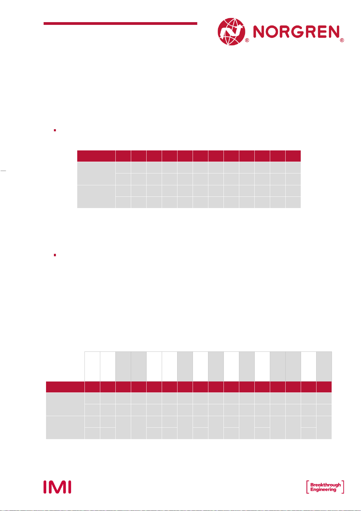
5.1 MAPPING RULES FOR VALVE STATIONS 12
If valve stations ≤12, 2 solenoid numbers are always reserved for each valve station.*
Detailed allocation is shown as below:
Station
#1
#2
#3
#4
#5
#6
#7
#8
#9
#10
#11
#12
Solenoid A
(14 Solenoid)
Sol.01
Sol.03
Sol.05
Sol.07
Sol.09
Sol.11
Sol.13
Sol.15
Sol.17
Sol.19
Sol.21
Sol.23
Output
0
Output
2
Output
4
Output
6
Output
8
Output
10
Output
12
Output
14
Output
16
Output
18
Output
20
Output
22
Solenoid B
(12 Solenoid)
Sol.02
Sol.04
Sol.06
Sol.08
Sol.10
Sol.12
Sol.14
Sol.16
Sol.18
Sol.20
Sol.22
Sol.24
Output
1
Output
3
Output
5
Output
7
Output
9
Output
11
Output
13
Output
15
Output
17
Output
19
Output
21
Output
23
Notes:
* For valve station with single solenoid, only Solenoid A (14 Solenoid) is connected.
Consider the one which is closest to control module as 1st station (Station #1)
5.2 MAPPING RULES FOR 12 VALVE STATIONS 24
If 12 < valve stations ≤24, special rules are required since only 1 solenoid number is
allocated to valve station with single solenoid:
•Sequence all solenoids following the rules below by starting from 1st station which is the
station closest to control module:
oIf 1st station is with double solenoids, sequence solenoid A as Sol.01, solenoid B as
Sol.02, following 2nd station solenoid A as Sol.03, solenoid B as Sol.04……
oIf 1st station is with single solenoid, sequence solenoid A as Sol.01, following 2nd
station solenoid A as Sol.02, solenoid B as Sol.03……
oIf a station is originally configured as blank, always 2 solenoid numbers are allocated.
oThe rest of stations should also adhere to the sequence rules above.
•A 16-station 24 solenoids valve manifold example is shown below:
Double
Solenoids
Double
Solenoids
Single
Solenoid
Single
Solenoid
Double
Solenoids
Double
Solenoids
Single
Solenoid
Double
Solenoids
Single
Solenoid
Double
Solenoids
Single
Solenoid
Double
Solenoids
Single
Solenoid
Single
Solenoid
Double
Solenoids
Single
Solenoid
Station
#1
#2
#3
#4
#5
#6
#7
#8
#9
#10
#11
#12
#13
#14
#15
#16
Solenoid A
(14 Solenoid)
Sol.01
Sol.03
Sol.05
Sol.06
Sol.07
Sol.09
Sol.11
Sol.12
Sol.14
Sol.15
Sol.17
Sol.18
Sol.20
Sol.21
Sol.22
Sol.24
Output
0
Output
2
Output
4
Output
5
Output
6
Output
8
Output
10
Output
11
Output
13
Output
14
Output
16
Output
17
Output
19
Output
20
Output
21
Output
23
Solenoid B
(12 Solenoid)
Sol.02
Sol.04
--*
--*
Sol.08
Sol.10
--*
Sol.13
--*
Sol.16
--*
Sol.19
--*
--*
Sol.23
--*
Output
1
Output
3
Output
7
Output
9
Output
12
Output
15
Output
18
Output
22
Note:
* For valve station with single solenoid, only Solenoid A (14 Solenoid) is allocated & connected.
Consider the one which is closest to control module as 1st station (Station #1).
11
Operation & Service Manual
VR10 / VR15 with PROFINET Interface
Construction & Design is subject to change (A1743-OPM-PN / Rev1)
6 COMMISSIONING
Notes:
1. The method of PROFINET module installation strongly depends on the configuration software. Please refer to the
configuration software manual, all examples in this document are made with Siemens PLC S7-1512C-1 PN and TIA
Portal V15.1.
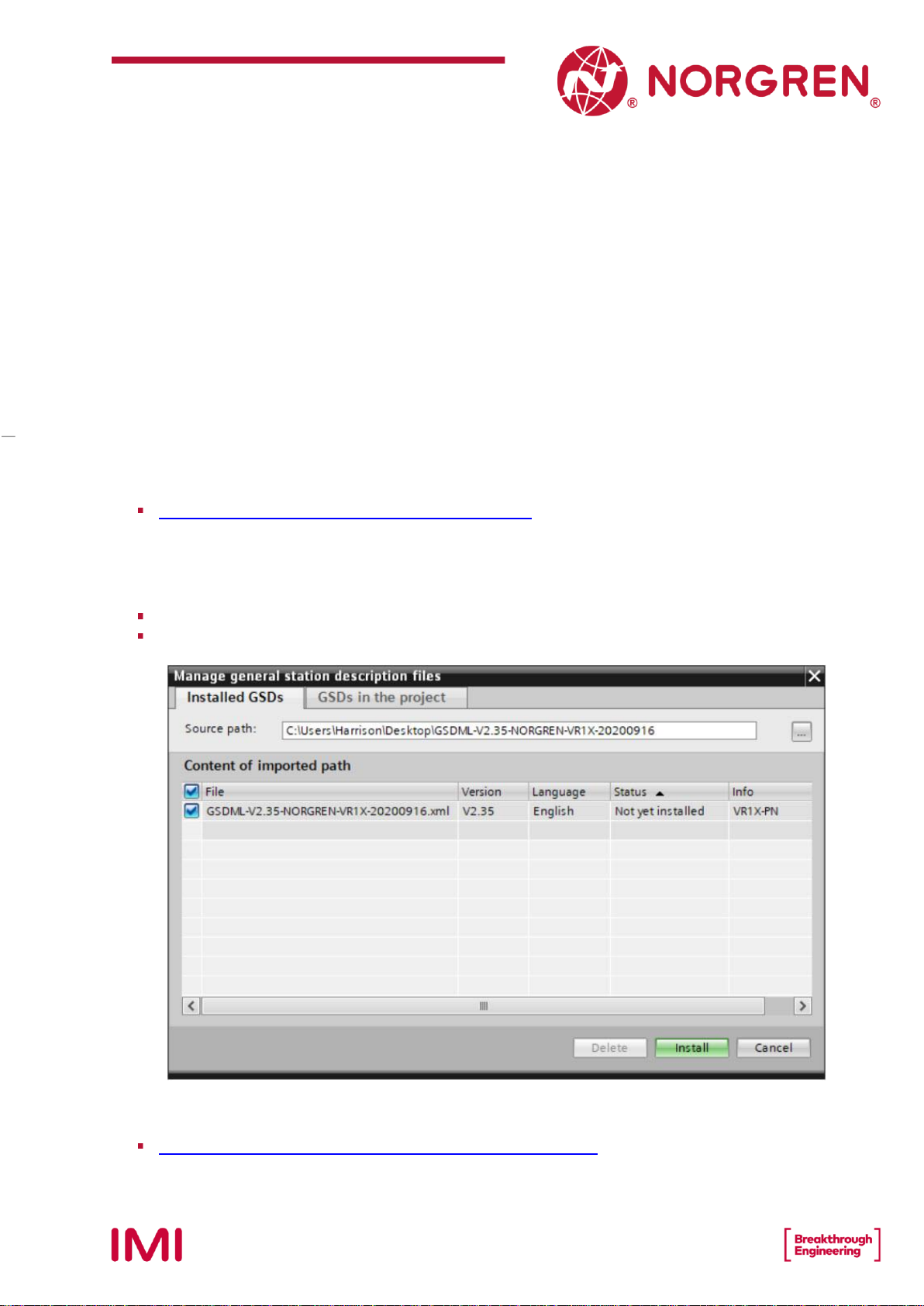
6.1 GSDML FILE INSTALLATION
A device description file is needed for configuration of valve manifold. The GSDML file is an XML
based file and could be used for all variants VR10 / VR15:
“GSDML-Vxx-NORGREN-VR1X-JJJJMMDD.xml”
Note: “JJJJMMDD” (JJJJ-year, MM-month, DD-day) is date of release, “Vxx” is version number of the file.
The GSDML file must be installed inside the engineering tool of the PROFINET controller:
Click “Options” -> “Manage general station description files (GSD)”.
Select source path where GSDML file is stored, tick the GSDML file and install.
The GSDML file is provided by Norgren and can be downloaded from the following web link:
https://www.norgren.com/us/en/technical-support/software
12
Operation & Service Manual
VR10 / VR15 with PROFINET Interface
Construction & Design is subject to change (A1743-OPM-PN / Rev1)
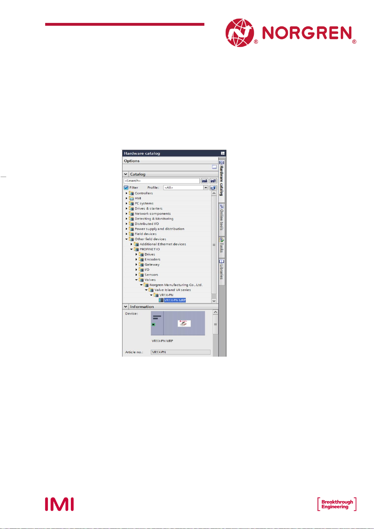
6.2 HARDWARE CONFIGURATION
After the successful installation of the GSDML file the VR10 / VR15 is listed in the hardware
catalog.
13
Operation & Service Manual
VR10 / VR15 with PROFINET Interface
Construction & Design is subject to change (A1743-OPM-PN / Rev1)
6.2.1 Add Valve Manifold
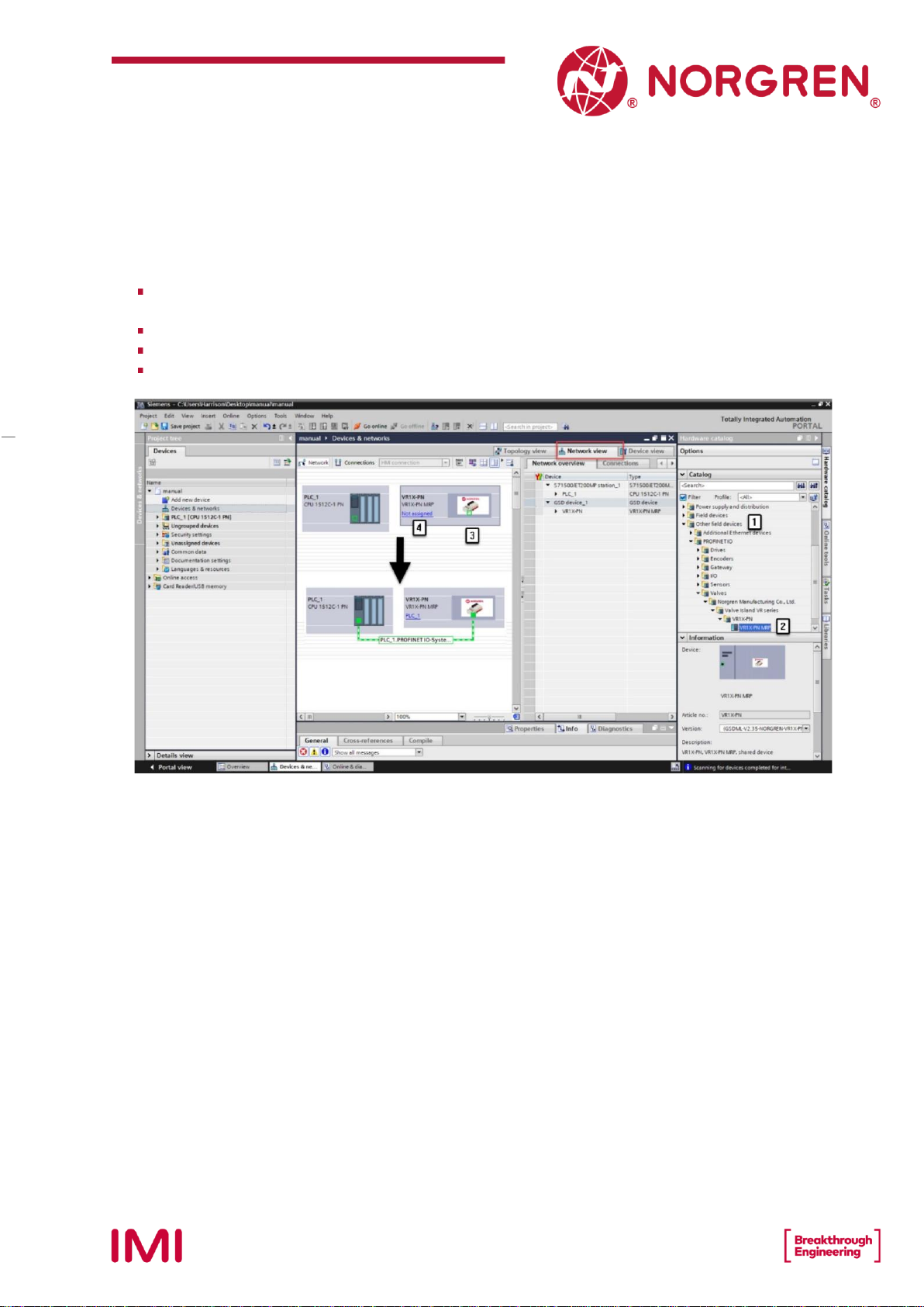
Expand “Other field devices” -> “PROFINET IO” -> “Valves” -> “Norgren Manufacturing Co.,
Ltd.” and find “VR1X-PN MRP” listed here. (Tag 1-2)
Double click or drag “VR1X-PN MRP” to drop it into Network view. (Tag 3)
Assign PLC to the valve manifold by clicking “Not assigned” button. (Tag 4)
The PLC controller and the valve manifold will be connected via green line.

14
Operation & Service Manual
VR10 / VR15 with PROFINET Interface
Construction & Design is subject to change (A1743-OPM-PN / Rev1)
Double click the added valve island in Network view to switch to Device view. (Tag 5)
Expand “Module” then double click “VR1X-PN with 10 bytes Input” module and “VR1X-PN
with 3 bytes Output” module in hardware catalogue. (Tag 6)
10 bytes Input are used for diagnostics, from input byte 0 to input byte 9.
3 bytes Output are allocated to 24 solenoids, from output byte 0 to output byte 2.
In this way the valve manifold input & output modules are put into matched slots
automatically and “I address” “Q address” are automatically allocated. (Tag 7)
15
Operation & Service Manual
VR10 / VR15 with PROFINET Interface
Construction & Design is subject to change (A1743-OPM-PN / Rev1)
6.2.2 Identifying Valve Manifolds in Network
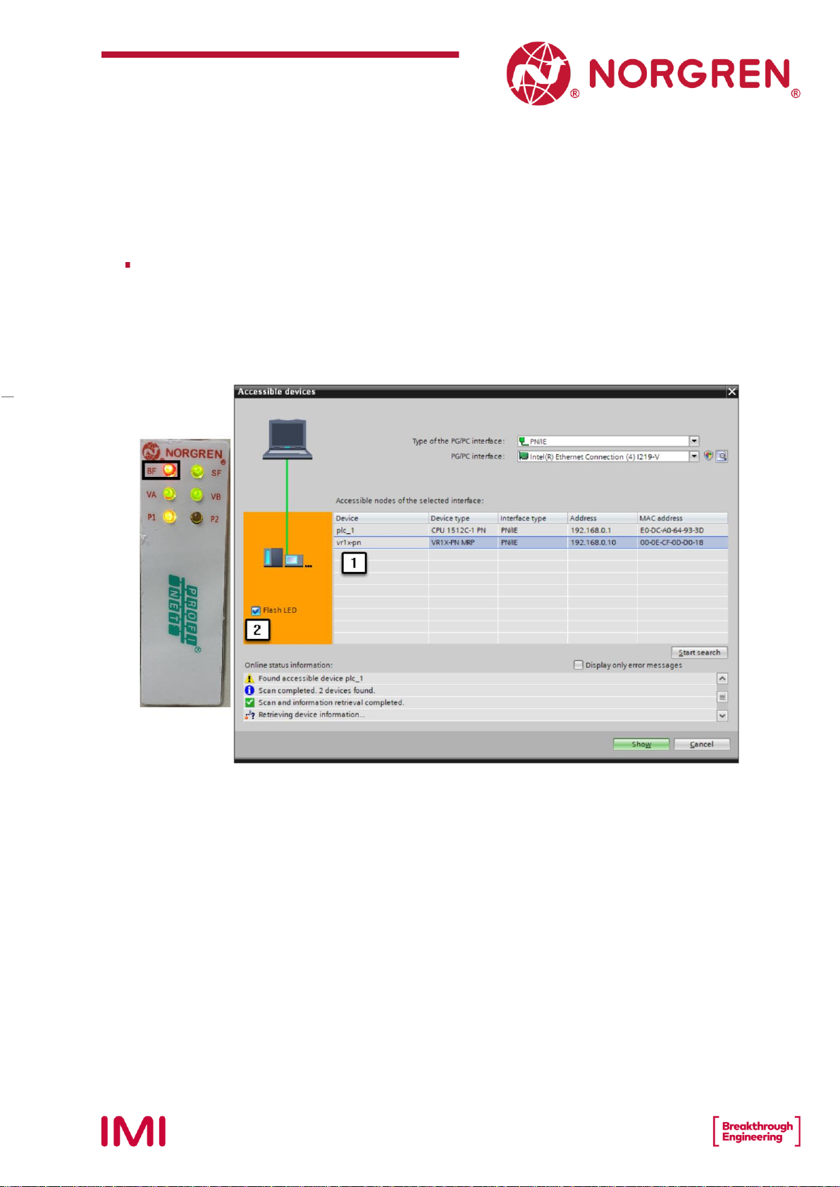
Blink Test
•Blinking BF LED can help to identify valve manifolds in the network.
•Select the valve manifold you want to identify then tick “Flash LED” in the left pane.
(Tag 1-2)
•BF LED will be blinking slowly, and this blinked valve manifold is the one identified.
•Repeat the steps to identify other valve manifolds.
16
Operation & Service Manual
VR10 / VR15 with PROFINET Interface
Construction & Design is subject to change (A1743-OPM-PN / Rev1)
6.3 PARAMETERIZATION
6.3.1 Open Load Diagnostics Setting
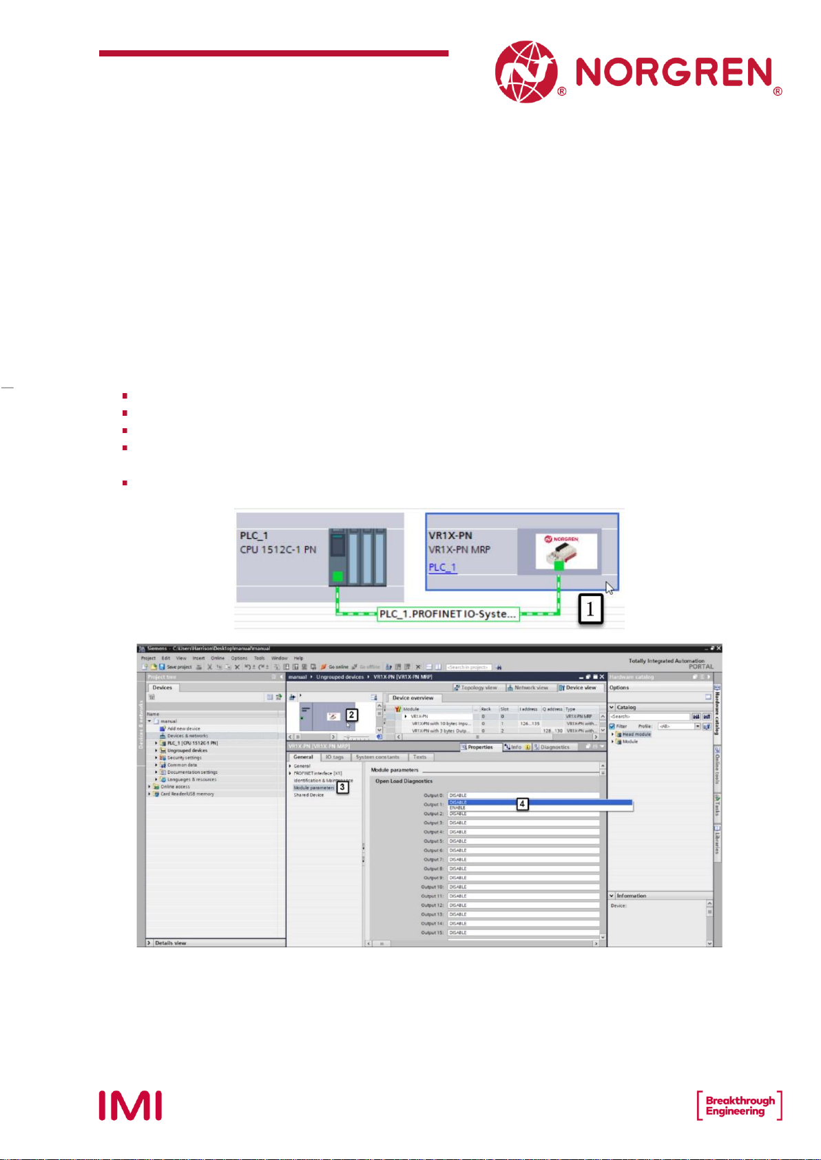
It is possible for VR10 / VR15 valve manifold to enable / disable the open load diagnostics for each
solenoid. If disabled, no PROFINET open load diagnostic error appears. Otherwise a PROFINET
channel diagnostic with error description and channel number appears and SF LED on the valve
manifold change color from green to red color.
Double click the added valve manifold in Network view to switch to Device view. (Tag 1)
Double click the added valve manifold in Device view. (Tag 2)
Select “Module parameters” option in General tag. (Tag 3)
Select “DISABLE / ENABLE” options for each solenoid to set open load diagnostics function.
(Tag 4)
Solenoid number and output point mapping relation is shown in Chapter 5.
17
Operation & Service Manual
VR10 / VR15 with PROFINET Interface
Construction & Design is subject to change (A1743-OPM-PN / Rev1)
6.3.2 Fail Safe State Setting
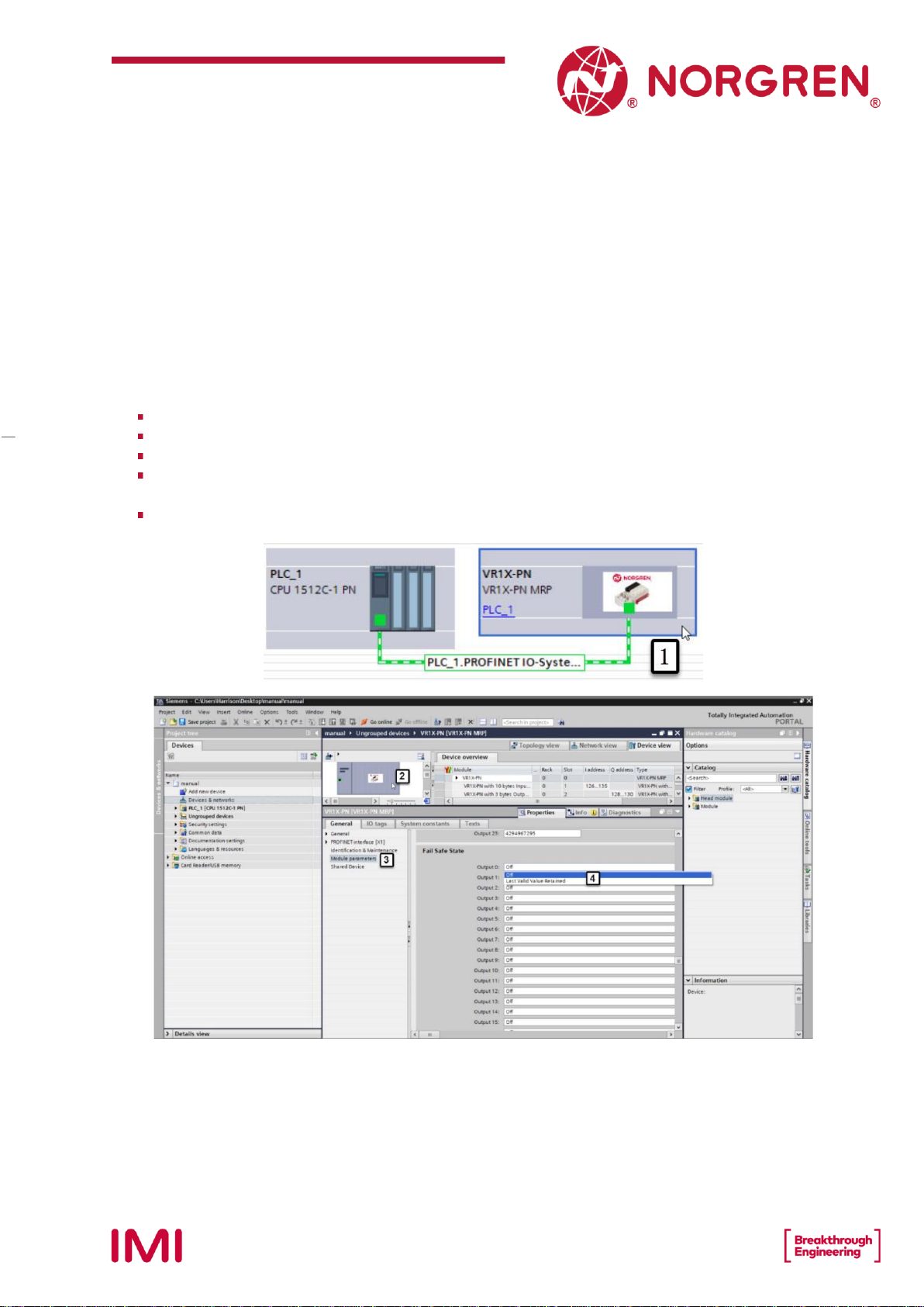
It is possible to define the behaviour of the outputs in case of broken PROFINET communication or
“IOPS = Bad” (PLC stopped). The following two states could be defined by the outputs:
1) Output —Off
2) Output —Last Valid Value Retained
Double click the added valve manifold in Network view to switch to Device view. (Tag 1)
Double click the added valve manifold in Device view. (Tag 2)
Select “Module parameters” option in General tag. (Tag 3)
Select “Off / Last Valid Value Retained” options for each solenoid to set fail safe state.
(Tag 4)
Solenoid number and output point mapping relation is shown in Chapter 5.

18
Operation & Service Manual
VR10 / VR15 with PROFINET Interface
Construction & Design is subject to change (A1743-OPM-PN / Rev1)
6.3.3 Voltage and Short Circuit Diagnostics
VR10 / VR15 valve manifold supports voltage diagnostics for both electronic power and valve
power and short circuit diagnostics for each solenoid. And these two diagnostic functions cannot
be disabled.
In case of over / under voltage a PROFINET module diagnostic with error description
appears and the related LEDs on the valve island change colour from green to red.
In case of short circuit an PROFINET channel diagnostic with error description and channel
number appears and SF LED on the valve island change colour from green to red.

19
Operation & Service Manual
VR10 / VR15 with PROFINET Interface
Construction & Design is subject to change (A1743-OPM-PN / Rev1)
6.3.4 Cycle Counter Setting
VR10 / VR15 valve manifold supports cycle counting, count limit set, and counter reset for each
solenoid. Cycle counting and counter reset can be achieved by programming.
Count limit set
•Double click the added valve manifold in Network view to switch to Device view. (Tag 1)
•Double click the added valve manifold in Device view. (Tag 2)
•Select “Module parameters” option in General tag. (Tag 3)
•Input the cycle counter limit in decimal for each solenoid. (Tag 4)
•The maximum limit value is 232-1.
•Solenoid number and output point mapping relation is shown in Chapter 5.

20
Operation & Service Manual
VR10 / VR15 with PROFINET Interface
Construction & Design is subject to change (A1743-OPM-PN / Rev1)
6.4 GO ONLINE AND MONITOR DATA
6.4.1 Compiling and Download
After finished configuration, compile the project, and download it to PROFINET controller (PLC).
6.4.2 Cycle Counting Data Acquisition
Monitor the “96-byte data array”, the cycle counting data will be displayed after each byte in
“Monitor value” column.
Other manuals for VR10
3
This manual suits for next models
1
Table of contents
Popular Industrial Equipment manuals by other brands

SCHUNK
SCHUNK ROTA THW 400 Assembly and operating manual

Xylem
Xylem ebro EBI TIB 400 manual

MUSASHI ENGINEERING
MUSASHI ENGINEERING ShotMaster 300SX instruction manual

Metcalfe
Metcalfe GU4 Installation & operating instructions

SCHUNK
SCHUNK OSE 34 Assembly and operating manual

Image Engineering
Image Engineering CAL3-XL user manual


