8
DescriptionRef
A= Clearance above grade, veranda, porch,
deck, or balcony
B= Clearance to window or door that may
be opened
C= Clearance to permanently closed window
D=
Vertical clearance to ventilated soffit located
above the terminal within a horizontal distance
of 2 feet (61 cm) from the center line of the terminal
*
E= Clearance to unventilated soffit *
F= Clearance to outside corner *
G= Clearance to inside corner *
H= Clearance to each side of center line
extended above meter/regulator assembly
I= Clearance to service regulator vent outlet
J=
Clearance to nonmechanical air supply
inlet to building or the combustion air inlet
to any other appliance
K= Clearance to a mechanical air supply inlet 6 ft (1.83 m)
L= Clearance above paved sidewalk or paved
driveway located on public property
Clearance under veranda, porch, deck,
or balcony
7 ft (2.13 m)†
M=
1 In accordance with the current CSA B149.1 Natural Gas and Propane Installation Code
2 In accordance with the current ANSI Z223.1 / NFPA 54 National Fuel Gas Code
† A vent shall not terminate directly above a sidewalk or paved driveway that is located between two single
family dwellings and serves both dwellings.
‡ Permitted only if veranda, porch, deck, or balcony is fully open on a minimum of two sides beneath the floor.
* Clearance in accordance with local installation codes and the requirements of the gas supplier.
Clearance to opposite wall is 24 inches (60 cm).
12 in (30 cm)‡
*
12 in (30 cm)
6 in (15 cm) for appliances
≤ 10,000 Btuh (3kW), 12 in
(30 cm) for appliances > 10,000
Btuh (3kW) and ≤ 100,000 Btuh
(30 kW), 36 in (91 cm) for
appliances > 100,000 Btuh (30 kW)
Above a regulator within 3 ft (91 cm)
horizontally of the vertical center line of
the regulator vent outlet to a maximum
vertical distance of 15 ft (4.5 m)
6 in (15 cm) for appliances
≤ 10,000 Btuh (3kW), 9 in
(23 cm) for appliances > 10,000
Btuh (3kW) and ≤ 50,000 Btuh
(15 kW), 12 in (30 cm) for
appliances > 50,000 Btuh (15 kW)
6 in (15 cm) for appliances
≤ 10,000 Btuh (3kW), 12 in
(30 cm) for appliances > 10,000
Btuh (3kW) and ≤ 100,000 Btuh
(30 kW), 36 in (91 cm) for
appliances > 100,000 Btuh (30 kW)
6 in (15 cm) for appliances
≤ 10,000 Btuh (3kW), 9 in
(23 cm) for appliances > 10,000
Btuh (3kW) and ≤ 50,000 Btuh
(15 kW), 12 in (30 cm) for
appliances > 50,000 Btuh (15 kW)
*
*
*
*
**
*
*
*
3 ft (91 cm) above if within
10 ft (3 m) horizontally
*
12 in (30 cm)
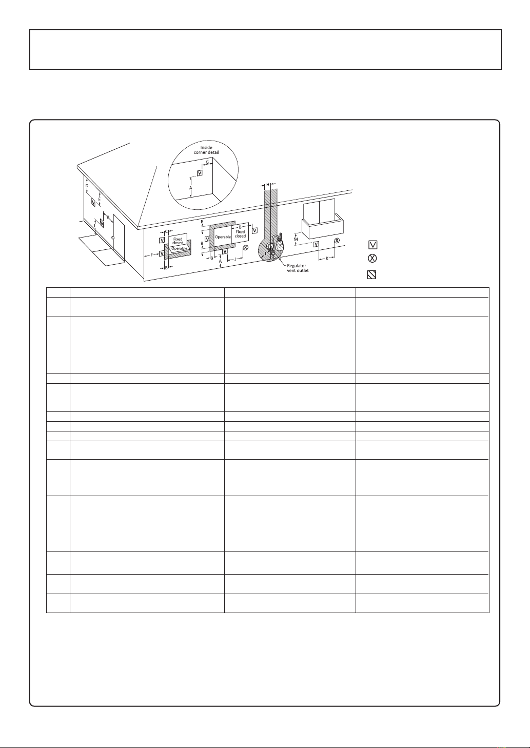
Vent Terminal
Air Supply Inlet
Area Where Terminal
is Not Permitted
I
US Direct Vent Installations 2
Canadian Direct Vent Installations 1
Clearance Requirements from Vent Terminations to Building Openings
<When supplying combustion air from the outdoors (Direct Vent)>
* All clearance requirements are in accordance with ANSI Z21.10.3 and the National Fuel Gas Code,
ANSI Z223.1 and in Canada, in accordance with the Natural Gas and Propane Installation Code
CSA B149.1.


 null")
 null")


 Operation and maintenance instructions")