manuals.online logo
Brands
  1. Home
  2. •
  3. Brands
  4. •
  5. Noritz
  6. •
  7. Water Heater
  8. •
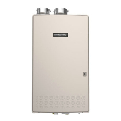
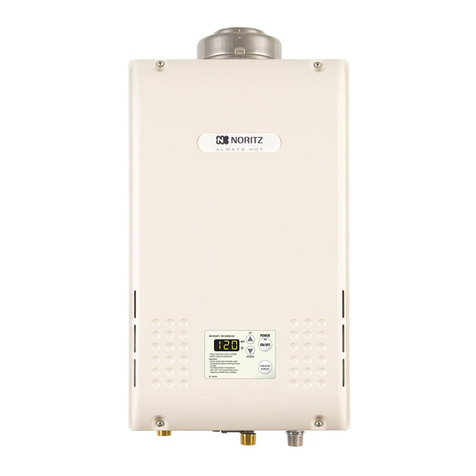
  9. Noritz NRC661A Series Use and care manual

Noritz NRC661A Series Use and care manual

This manual suits for next models

5

Other Noritz Water Heater manuals

Noritz NR98-DVC-CA User manual

Noritz

Noritz NR98-DVC-CA User manual

Noritz NRC98-DV User manual

Noritz

Noritz NRC98-DV User manual

Noritz GQ-C3257WZ-FF US User manual

Noritz

Noritz GQ-C3257WZ-FF US User manual

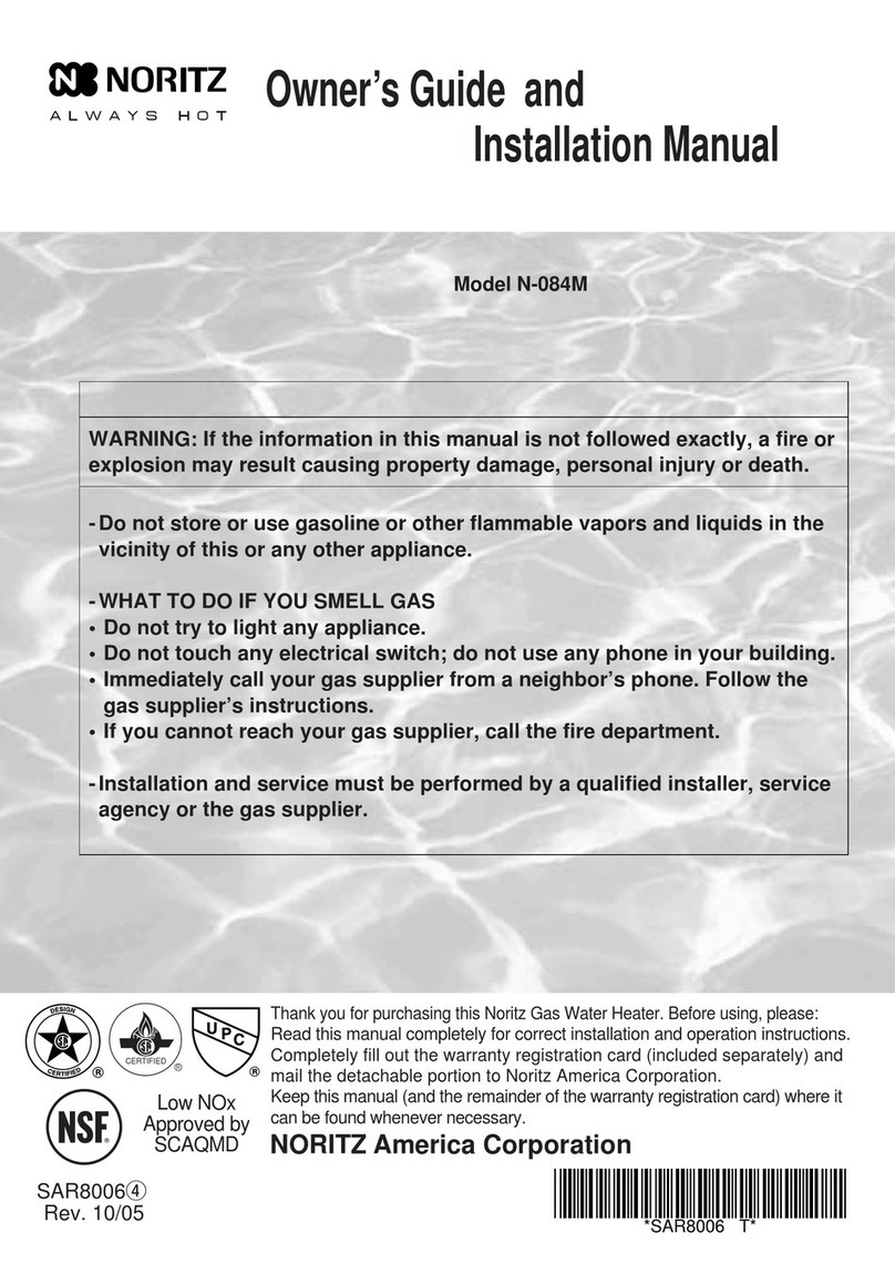
Noritz N-084M-DV Instruction manual

Noritz

Noritz N-084M-DV Instruction manual

Noritz NR71-SV User manual

Noritz

Noritz NR71-SV User manual

Noritz NRCP1112-DV User manual

Noritz

Noritz NRCP1112-DV User manual

Noritz NRC661 Series User manual

Noritz

Noritz NRC661 Series User manual

Noritz proTough NR98DVC User manual

Noritz

Noritz proTough NR98DVC User manual

Noritz NRC1111-DV User manual

Noritz

Noritz NRC1111-DV User manual

Noritz N-132M Instruction manual

Noritz

Noritz N-132M Instruction manual
Noritz NCC199DV-NG User manual

Noritz

Noritz NCC199DV-NG User manual

Noritz NR111-SV User manual

Noritz

Noritz NR111-SV User manual

Noritz N-0751M-OD User manual

Noritz

Noritz N-0751M-OD User manual

Noritz N-0931M-ASME User manual

Noritz

Noritz N-0931M-ASME User manual

Noritz N-0751M User manual

Noritz

Noritz N-0751M User manual

Noritz NRC663-FSV User manual

Noritz

Noritz NRC663-FSV User manual

Noritz NCC300DV User manual

Noritz

Noritz NCC300DV User manual
Noritz GQ-2857WX-FFA US User manual

Noritz

Noritz GQ-2857WX-FFA US User manual

Noritz NR98-DVC-CA User manual

Noritz

Noritz NR98-DVC-CA User manual

Noritz NR83-DVC User manual

Noritz

Noritz NR83-DVC User manual

Noritz ecoTOUGH NRC111-OD-NG User manual

Noritz

Noritz ecoTOUGH NRC111-OD-NG User manual

Noritz NCC300OD User manual

Noritz

Noritz NCC300OD User manual

Noritz ecoTOUGH NRC71 OD User manual

Noritz

Noritz ecoTOUGH NRC71 OD User manual

Noritz NC250-SV-ASME User manual

Noritz

Noritz NC250-SV-ASME User manual

Popular Water Heater manuals by other brands

clage German pool CEX13 operating instructions

clage

clage German pool CEX13 operating instructions

DeDietrich KALIKO TWH 200 EV Installation and service manual

DeDietrich

DeDietrich KALIKO TWH 200 EV Installation and service manual

veito FLOW Installation and operating instructions

veito

veito FLOW Installation and operating instructions

ICI Caldaie COSMOGAS AGUATANK 150 Instructions for installation, use and maintenance manual

ICI Caldaie

ICI Caldaie COSMOGAS AGUATANK 150 Instructions for installation, use and maintenance manual

Savio Laser 11 A Instruction manual for installation and use

Savio

Savio Laser 11 A Instruction manual for installation and use

Kenmore 153.582400 Use & care guide

Kenmore

Kenmore 153.582400 Use & care guide

STIEBEL ELTRON Eltronom SHU 5 S Operating and installation instructions

STIEBEL ELTRON

STIEBEL ELTRON Eltronom SHU 5 S Operating and installation instructions

clage E-Mini Series Operating and installation instructions

clage

clage E-Mini Series Operating and installation instructions

Solar SunX 317365-002 instruction manual

Solar

Solar SunX 317365-002 instruction manual

Bradford White EF Series Service manual

Bradford White

Bradford White EF Series Service manual

Dimplex ECSd125-580 Installation and user instructions

Dimplex

Dimplex ECSd125-580 Installation and user instructions

Dux 32FCR6N installation manual

Dux

Dux 32FCR6N installation manual

TESY GCV7/4S 10047 Instructions for use and maintenance

TESY

TESY GCV7/4S 10047 Instructions for use and maintenance

A.O. Smith Gphe 50 instruction manual

A.O. Smith

A.O. Smith Gphe 50 instruction manual

Rinnai REP199i Installation and operation manual

Rinnai

Rinnai REP199i Installation and operation manual

Toyotomi Oil Miser OM-148 (Type D) Operation and maintenance instructions

Toyotomi

Toyotomi Oil Miser OM-148 (Type D) Operation and maintenance instructions

Koryo KWHZF15Y user manual

Koryo

Koryo KWHZF15Y user manual

Pentair PSC-14-4-02 Installation and operation manual

Pentair

Pentair PSC-14-4-02 Installation and operation manual

manuals.online logo
manuals.online logoBrands
  • About & Mission
  • Contact us
  • Privacy Policy
  • Terms and Conditions

Copyright 2025 Manuals.Online. All Rights Reserved.

SKJ70RF
Rev. 10/13
NRC661A-DV, NRC661A-OD, NRC711-DV, NRC711-OD
This instru tional manual is only intended for use by a qualified servi e professional or authorized Noritz
NRC661A, NRC711 Series Heat Ex hanger
Repla ement
Model In lude:
Page 1
Noritz Ameri a Corporation
11160 Gra e Avenue, Fountain Valley, CA 92708
Phone 866-766-7489 Fax 714-241-1196
Servi e Representative. Any unauthorized use of this manual may result in voiding the warranty.
Please onta t Noritz Te hni al Support (866-766-7489) for additional support.
NRC661A, NRC711 Series Heat Ex hanger Repla ement Pro edure
Diagram
1.
(1) Dis onne t ele tri al power to the unit
(2) Turn off gas and water
(3) Remove 4 s rews
(4) Remove drain 2 valves and drain unit ompletely
(5) Remove the over - ir uit board
2.
(1) Dis onne t the onne tors from ir uit board
(2) Remove the ground wire
DV model; 3 ground wires
OD model; 2 ground wires
(3) Remove the ir uit board; there are 2 s rews, one on
the right-side and middle-upper of the ir uit board.
Let the ir uit board hang outside of the unit
3.
(1) Unplug Flame Rod and Ignition Plug
(2) Loosen the wire an hor from right side of the ase and
unplug the freeze prevention heater, thermal fuse (2)
(3) Unplug all wires that atta h to the wiring harness
ex ept the water servo - main
(4) *DV model only
Unplug the freeze
prevention heater,
the thermistor
- exhaust.
Release the wire
lamps
Page 2
Unplug all wires that atta h to the wiring harness and the body
of the water heater
Pro edure
Remove the front over
Dis onne t the onne tors from the ir uit board and remove
the ground wire, the ir uit board
OD model has only a s rew
of the upperside
Water Servo - Main
(3)
(1) (2)
Cover - Cir uit Board
(4) Wire lamp
NRC661A, NRC711 Series Heat Ex hanger Repla ement Pro edure
Diagram
4.
(1) Remove 3 big silver s rews on the manifold plate that
atta h the manifold to the burner
(2) Remove 2 smaller silver s rews from the manifold
plate that atta h the manifold to the gas valve
(3) Remove the manifold plate and unplug the onne tor
from gas solenoid valves (3)
5.
(1) Remove "C" Clamp (3)
(2) Remove the water flow sensor
(3) Make sure to feed the wires from the water servo -
main around the outlet water pipe as shown in
bottom diagram
Page 3
Pro edure
Remove the manifold plate
Dis onne t water pipes from the water flow sensor and the
water servo - main
(1)
(1)
(2,3)
Water Flow Sensor
Wiring harness
(2)
(3)
NRC661A, NRC711 Series Heat Ex hanger Repla ement Pro edure
Diagram
6.
(1) Dis onne t the venting from the unit
(2) Remove 4 s rews and pull the flue off of the unit and
set aside
7.
(1) Remove 1 spring lamp
(2) Remove the drain hose from SS HE and pull the hose
out as shown in the right diagram (2)
8.
(1) Remove the over - water level ele trode from the
ondensate ontainer
(2) Unplug the water level ele trode wiring, the high limit
swit h and the thermistor - heat ex hanger wiring
harness as shown in diagram (2)
(3) Make sure to feed the wires from the water level
ele trode wiring harness outside the ase as shown in
diagram (3)
Page 4
Remove the over and route wires - water level ele trode
Pro edure
Remove the exhaust flue from top of the unit *DV model
only
Remove the drain hose from Stainless Steel Heat
Ex hanger(SS HE)
(1)
(2)
(1)
(2)
(3)
NRC661A, NRC711 Series Heat Ex hanger Repla ement Pro edure
Diagram
9.
(1) Remove the 2 set s rews on the bottom of the burner
(2) Remove the upper left and right set s rews near the
top of the ase (In OD Model, the s rews will be at the
top of the ase)
(support bottom of assembly)
(3) SS HE, Copper Heat Ex hanger(CU HE), Burner, and
Fan will ome out in one se tion. Remove from the
unit
10.
(1) Remove 2 s rews on the bra ket between the SS HE
and the CU HE
(2) Remove the 3 s rews that lo ated on the ba k side of
the SS HE
(3) Remove "C" lamp
(4) Separate the SS HE from the CU HE
Page 5
Pro edure
Remove the heat ex hanger from the ase
Separate the SS HE from the CU HE
(1)
(2) DV model
(2) OD model
(2)
(3)
(1)
NRC661A, NRC711 Series Heat Ex hanger Repla ement Pro edure
Diagram
11.
(1) Remove old gasket between the SS HE and the CU HE
Exhaust Box and repla e with new one
(2)
*OD model only
Remove the gasket on the front of the SS HE and pla e
on new one
12.
(1) Remove 10 s rews holding the burner to the CU HE
(2) Separate the burner from the CU HE
13.
(1) Front side: Freeze Prevention Heater
(2) Left side: High limit Swit h and Thermistor - Heat
Ex hanger
*Repla e new O Ring fot the thermistor - heat
ex hanger
Page 6
Remove heat ex hanger omponents from old heat ex hanger
and put on new heat ex hanger
Pro edure
Repla ing the CU HE
Repla ing the SS HE
Note: If you are not repla ing the SS HE then you an skip this
step and set the SS HE aside.
(1)
(2) OD model only
NRC661A, NRC711 Series Heat Ex hanger Repla ement Pro edure
Diagram
(3) Atta h the thermal fuse and 5 lamps from 4 sides of
the heat ex hanger, See 4 views of the heat
ex hanger to make sure the thermal fuse is routed
orre tly
Page 7
Pro edure
The end of insulation tube(Bla k) and the
front of the heat ex hanger are lined up
Right side
Install the thermal fuse(White) inside of
the stopper
Stopper
Ba k side
Keep the thermal fuse straight
Left side - 1
Make sure to route the thermal
fuse as shown in the diagram to
the right (Left side - 1, 2)
Front side
Left side - 2
NRC661A, NRC711 Series Heat Ex hanger Repla ement Pro edure
Diagram
(4)
*DV model only
Pla e the new freeze prevention heater with one that
was shipped in the heat ex hanger kit.
Wrap the freeze prevention heater around inlet pipe to
the CU HE.
14.
(1) Remove old burner gasket and repla e with new one
15.
(1) Inlet to the CU HE
(2) Outlet from the CU HE
Page 8
Pro edure
Repla e gaskets
Pla e new O Rings on new CU HE
(2)(1)
(1)
Left side of HE
NRC661A, NRC711 Series Heat Ex hanger Repla ement Pro edure
Diagram
16.
(1) Atta h the inlet pipe to the CU HE with the “C” Clamp.
Make sure to insert the pipe in all the way before
atta hing “C” Clamp.
(2) Atta h 3 s rews that lo ated on the ba k side of the SS
HE to hold the SS HE to the CU HE
(3) Atta h 2 s rews on the bra ket between the SS HE and
the CU HE
(4) Atta h 10 s rews around perimeter of the burner and
the CU HE
17.
(1) Se ure the 2 set s rews on the bottom of the burner
(2) Se ure the upper left and right set s rews near the top
of the ase (In OD model, the s rews will be at the top
of the ase)
Page 9
Repla e the assembly ba k inside the ase
Pro edure
Reatta h Burner, CU HE, and SS HE
(2)
(1)
(4)
(1)
(2) OD model
(2) DV model
(3)
NRC661A, NRC711 Series Heat Ex hanger Repla ement Pro edure
Diagram
18.
(1) Atta h the flue to the unit and se ure the 4 s rews
(2) Re onne t the venting to the unit
19.
(1) Maintain the high limit swit h, the thermistor - heat
ex hanger and the water level ele trode wiring harness
as shown in diagram (1)
(2)
*DV model only
Maintain the freeze prevention heater and the
thermistor - exhaust wiring harness as shown in
diagram (2)
(3) Maintain wiring harness as shown in diagram (3)
(4) Insert the pipe from the CU HE to the water servo -
main and atta h "C" lamp
(5) Insert the water flow sensor to the inlet water
onne tion and atta h "C" lamp.
And then insert the water inlet pipe to the water flow
sensor and atta h "C" lamp.
20.
(1) Repla e the drain hose to the SS HE and reatta h 1
spring lamp as right diagram (1)
Page 10
Pro edure
Re onne t water onne tions
Repla e the drain hose to the SS HE
Repla e the flue from top of the unit
*DV model only
(1)
(2)
(5)
(4)
(3)
(1)