Norsat WAYFARER 1.2M KA-BAND User manual

USER MANUAL
WAYFARER 1.2M KA-BAND
AUTO-ACQUIRE FLY-AWAY ANTENNA

©Norsat International Inc. (“Norsat”) All Rights Reserved
2021-08-06 050196 Rev E 2
TABLE OF CONTENTS
Acronyms................................................................................................................................... 3
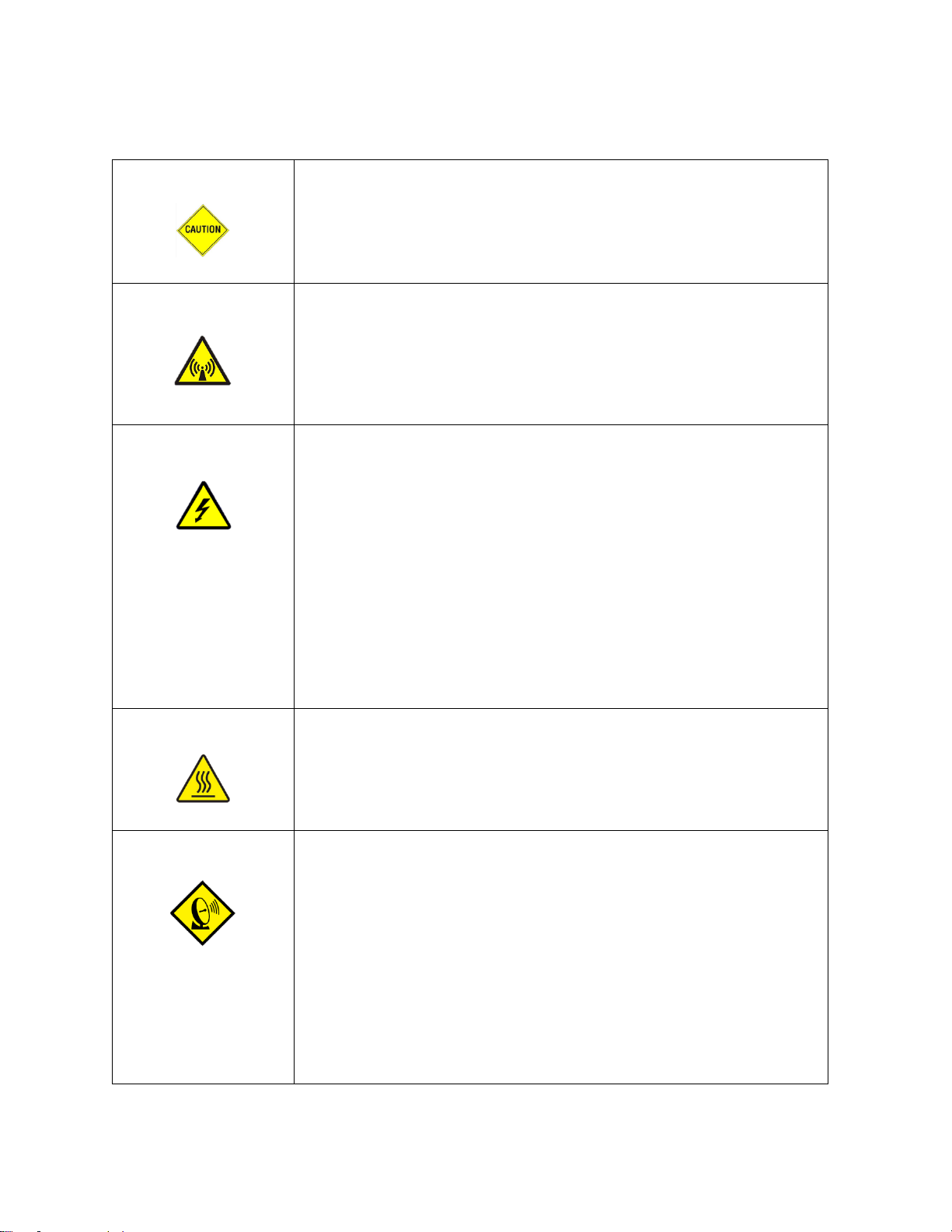
Safety ........................................................................................................................................ 4
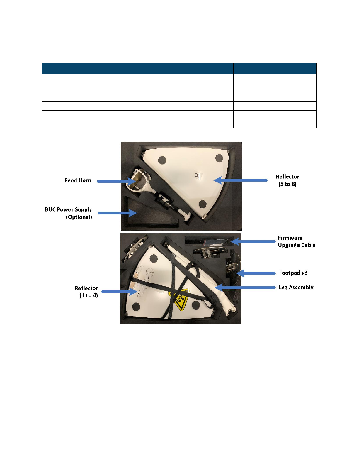
List of Contents.......................................................................................................................... 6
Case 1 ................................................................................................................................... 6
Case 2 ................................................................................................................................... 7
Product Overview............................................................................................................... 8
System Overview ............................................................................................................... 8
Hardware ........................................................................................................................... 9
3.1 Case Dimensions......................................................................................................... 9
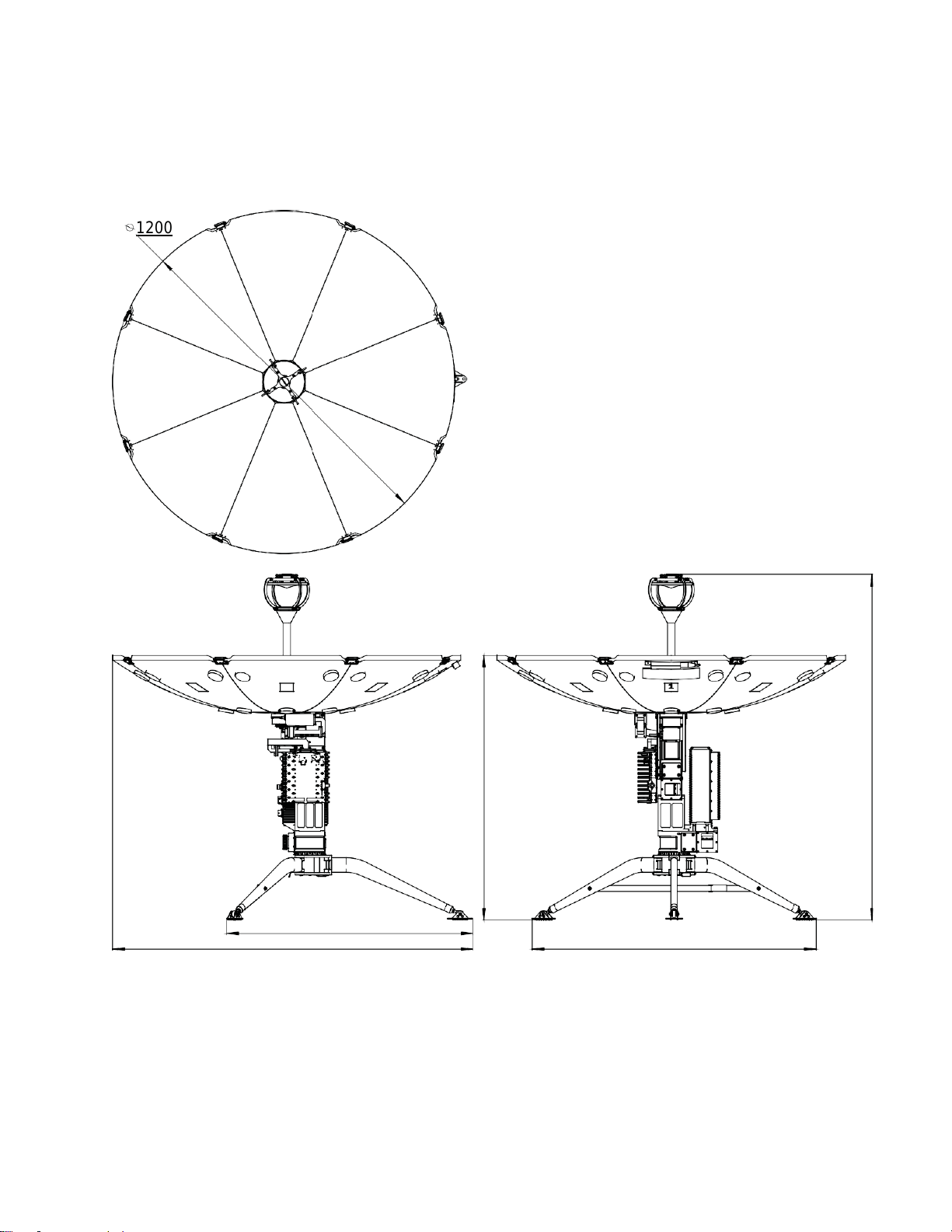
3.2 Antenna Dimensions...................................................................................................10
Electrical ...........................................................................................................................12
4.1 Power Supply..............................................................................................................12
4.2 Antenna Control Unit...................................................................................................12
4.3 Antenna Control Unit...................................................................................................13
Quick Start ........................................................................................................................15
5.1 Antenna Assembly......................................................................................................15
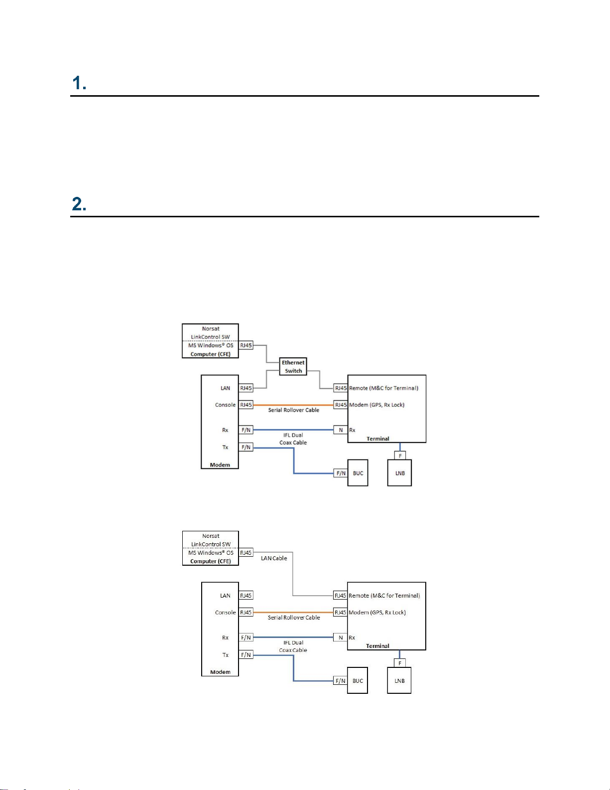
5.2 Cable Connection .......................................................................................................20
5.3 Auto-Acquire...............................................................................................................22
System Maintenance.........................................................................................................26
Factory Reset....................................................................................................................26
Technical Specification......................................................................................................27
Appendix A –Magnetic Declination Map...................................................................................28

©Norsat International Inc. (“Norsat”) All Rights Reserved
2021-08-06 050196 Rev E 3
Acronyms
ACU
Antenna Control Unit
AZ
Azimuth
BUC
Block Upconverter
CCW
Counter clockwise
CW
Clockwise
EL
Elevation
IFL
Interfacility Link
LNB
Low-noise Block Downconverter
M&C
Monitor and Control
OMT
Orthomode Transducer
POL
Polarization

©Norsat International Inc. (“Norsat”) All Rights Reserved
2021-08-06 050196 Rev E 4
Safety
Caution
Grounding the Terminal
Ground the system with a grounding conductor in accordance to national
and local electrical codes.
Danger
FCC Radio Frequency Exposure Information for Mobile Transmitting
Devices
When the power is on, do not stand within the line of sight of the terminal to
the satellite and maintain an off-axis clearance distance of a full reflector
diameter length from the centre of the beam.
Danger
Electrical Hazards in Wet and Windy Conditions
While the terminal is designed for outdoor use (e.g. optional waterproof
power supply), observe the following safety precautions during windy and
wet weather conditions. Some steps may not apply depending on the BUC
configuration.
1. Check cable connectors and power cords for damage or tears. Replace
cables and cords as needed.
2. Disconnect the terminal from its power source before you move it.
3. Disconnect the terminal from its power source if you suspect a power
malfunction
Warning
Hot Surfaces
When transmitting, do not touch the BUC as it may result in burns or injury.
Danger
Hazards of Microwave Radiation in Electromagnetic Fields
When the power is on, the area directly in front of the antenna is an Area of
Restricted Occupancy. Observe the following safety precautions:
1. Limithumanexposure timetothe areadirectlyinfront ofthemainantenna
assembly.
2. NeverplaceanypartofyourbodybetweentheantennaandtheFeedHorn
assembly.
3. Neverplaceanypartofyourbodyinlinewiththedirectionoftheantenna
transmissionpath.
4. Locate the terminal as far as possible from ungrounded metal.

©Norsat International Inc. (“Norsat”) All Rights Reserved
2021-08-06 050196 Rev E 5
Danger
Dielectric Heating
Dielectric heating is the heating of an insulating material caused by placing it
in a high frequency electric field. When a human enters a Radio Frequency
(RF) field, the body acts as dielectric. If the power in the RF field exceeds 10
milliwatts per centimetre, the individual will have a noticeable rise in body
temperature.
The severity of burns may vary from minor to major. Burns or other damage
may result in long term injury or even death.
The vital organs of the body are highly susceptible to dielectric heating.
The eyes are also highly susceptible to dielectric heating. Do not look
directly into devices radiating RF energy.
You must not stand directly in the path of RF radiating devices
Warning
Unintentional Radio Interference
This equipment generates, uses, and radiates radio frequency energy. If you
install and use the device according to the instruction manual, the device
will not cause harmful interference to radio communications.
If you operate the device in a residential area, it is likely to cause harmful
interference to radio communications; you will correct the interference at
your own expense.
Warning
Changes or Modifications to Equipment
Changesormodificationstothisequipment,notexpresslyapprovedbythe
manufacturer
could void the user’s authority to operate the equipment.
Accessories and Devices
Useofnon-approvedaccessories ordevicesmay leadtoadegradationin
performance, damage to equipment, or potential hazards
Servicing the Equipment
Do not service the equipment alone unless another person is present to
administer first-aid

©Norsat International Inc. (“Norsat”) All Rights Reserved
2021-08-06 050196 Rev E 6
List of Contents
Case 1
COMPONENTS
QUANTITY
Pedestal Assembly (ODU)
1
Antenna Power Supply
1
Sensor Cable
1
Remote Cable
1
Modem Cable (Optional)
1
IFL Cable (Optional)
1

©Norsat International Inc. (“Norsat”) All Rights Reserved
2021-08-06 050196 Rev E 7
Case 2
COMPONENTS
QUANTITY
Reflector Petals
8
Feed Horn
1
Leg Assembly
1
Footpad
3
Firmware Upgrade Cable
1
BUC Power Supply (Optional)
1

©Norsat International Inc. (“Norsat”) All Rights Reserved
2021-08-06 050196 Rev E 8
Product Overview
The Norsat WAYFARER is an industrial strength transportable satellite communication system
built strong for the most demanding users working with the most challenging applications and
environments. The WAYFARER is fully automated, integrated, and versatile enough for
deployment virtually anywhere, including mobile field offices, field vehicles, or directly on the
ground. A complete satellite solution, the WAYFARER includes everything to meet your
communication needs.
System Overview
The system consists of an antenna control unit, antenna drive unit, I/O unit, GPS module, beacon
receiver, DVB receiver, compass, inclinometer and other instruments.
Refer to the images below for the system block diagram using an OpenAMIP and Non-OpenAMIP
implementation. Refer to the LinkControl user manual for more information about OpenAMIP.
OpenAMIP System Block Diagram
Non-OpenAMIP System Block Diagram

©Norsat International Inc. (“Norsat”) All Rights Reserved
2021-08-06 050196 Rev E 9
Hardware
3.1 Case Dimensions
CASE
MODEL
DIMENSIONS
1 (Pedestal)
Pelican iM2950
79.5 x 51.8 x 31 cm
2 (Tripod, Feed, Reflector)
Pelican iM3075
84.6 x 62 x 49 cm
Case 1
Case 2

©Norsat International Inc. (“Norsat”) All Rights Reserved
2021-08-06 050196 Rev E 10
3.2 Antenna Dimensions
All dimensions are in millimeters.
848
1295
1200
977
913
1192
1242

©Norsat International Inc. (“Norsat”) All Rights Reserved
2021-08-06 050196 Rev E 11
All dimensions are in millimeters.
1295

©Norsat International Inc. (“Norsat”) All Rights Reserved
2021-08-06 050196 Rev E 12
Electrical
4.1 Power Supply
COMPONENT
REQUIREMENT
Antenna Power Supply
Antenna is powered by a power supply that requires 110-240V AC input
LNB
LNB is powered by 15V DC from ACU through Rx cable
BUC
BUC up to 8W can be powered by 24V DC from modem through IFL
cable. 20W and 40W ATOMBUC requires 48V DC input from at least
300W power supply
4.2 Antenna Control Unit
Antenna Control Unit is integrated with the pedestal
All ports and switches are installed onto the ACU, as shown below:
PORT
DESCRIPTION
Sensor
Compass signal input from compass on reflector petal 1
One Button
One button control for antenna resetting, satellite
pointing, stowing and stopping motion without the
handheld device
1. Press button and release after one beep,
antenna will reset and verify limit switches
2. Press button and release after two beeps,
antenna will start pointing to the last satellite it
has successfully acquired
3. Press button and release after three beeps,
antenna will stow
Remote
RJ45 ethernet port for LinkControl Client
Modem
RJ45 port for modem
On/Off
Power switch for antenna
Rx
Rx signal output from LNB
DC IN
24V DC power input, to be connected to supplied AC
power adapter

©Norsat International Inc. (“Norsat”) All Rights Reserved
2021-08-06 050196 Rev E 13
4.3 Antenna Control Unit
Azimuth and Elevation Modules
Azimuth module consists of azimuth motor, planetary gearbox, worm gearbox, internal gear and
azimuth base. The azimuth movement is mechanically self-locking and can be manually
controlled through the lower knob on pedestal Elevation module consists of: Elevation motor,
elevation gearbox and elevation base. The motor incorporates electromagnetic braking. Thus, the
elevation angle can be maintained in case of power outage. The elevation angle can be manually
controlled through the upper knob on pedestal.
Polarization Module
The polarization module consists of polarization motor, feed assembly, gearbox, duplexer, filter
and LNB. The polarization module’s main functionality is to adjust the polarization angle and
isolate the Tx/Rx signal.
The installation of polarization module is optimized from factory to ensure best performance.
Should the polarization module be removed, please mark the location of mounting screws on the
slot beforehand.
GPS Receiver
GPS module is installed inside the ACU. GPS lock/ not locked indicator can be observed through
the plastic cap on top of the ACU. When the indicator is blinking, the GPS is not locked and when
indicator is on, the GPS is locked. GPS Lock/ Not locked and latitude and longitude information
are showing in real time LinkControl.
3D Compass/Inclinometer
The compass/ inclinometer is mounted onto the reflector petal 1. The device provides heading
and elevation angle to ACU. The heading information is updated upon system reset.

©Norsat International Inc. (“Norsat”) All Rights Reserved
2021-08-06 050196 Rev E 14
Modem Port
The modem port is designed to be integrated with iDirect Modems. The ACU outputs the GPS
signal
Adjustment Knobs
Adjustment knobs for Azimuth and Elevation are available on the antenna for use in case of
emergency.

©Norsat International Inc. (“Norsat”) All Rights Reserved
2021-08-06 050196 Rev E 15
Quick Start
5.1 Antenna Assembly
1. Pull out the tripod.
2. Unfold the legs to limit and buckle up the strap so that the legs are sturdy.
3. Take out the footpads and mount them onto the tripod by following the instructions
below:
Release the pin from the
Footpad
Insert the Leg Joint into
the Footpad from top
Push in the button onthe
pin and insert from side
Ensure pin goes through
the mounting hole
4. Pull up the metal latch on the side of the tripod.
Note: Ensure the latch remains pulled up until the pedestal is inserted into the tripod.
5. If this is a high wind condition, stake down or add ballast weight to the tripod legs.
Tripod
Latch
Strap

©Norsat International Inc. (“Norsat”) All Rights Reserved
2021-08-06 050196 Rev E 16
6. Take out the pedestal.
7. Orientate the pedestal so its thumbscrews and handle face upwards while the azimuth
connector faces downwards.
8. Carry the pedestal by the handle at the top of the pedestal.
9. Insert the azimuth connector into the tripod center.
10. Ensure the pedestal sits flat onto the tripod.
11. Adjust the orientation so that front points to the satellite belt.
Azimuth
Connector
Thumbscrews
Handle

©Norsat International Inc. (“Norsat”) All Rights Reserved
2021-08-06 050196 Rev E 17
12. Push down the latch on the tripod to lock the pedestal into place.
13. Take out the feed assembly.
14. Remove the feed cover by holding the feed collar and rotating the feed cover
counterclockwise.
15. Remove feed mount cover from top of pedestal.
Note: Both exposed feed interfaces on the feed assembly and pedestal will have a
matching slot and pin respectively.
Feed Collar
Locating Pin
Slot
Feed Cover

©Norsat International Inc. (“Norsat”) All Rights Reserved
2021-08-06 050196 Rev E 18
16. Align the locating pin from feed mount to the indented slot.
17. Assemble feed to feed mount by tightening the feed collar clockwise.
Note: At this stage, the terminal should look like as follows:
18. Unpack the reflector petals.
Note: Each petal is labeled with a number from 1 to 8 with a corresponding position on
the pedestal.
Thumb Screw
Petal 1

©Norsat International Inc. (“Norsat”) All Rights Reserved
2021-08-06 050196 Rev E 19
19. Repeat the following steps when installing petals 1 through 8 in ascending order:
a. Loosen the thumbscrew to limit
b. Insert the reflector petal into the pedestal
c. Lock the reflector petal into place by tightening the thumbscrew.
d. Engage the latch between any adjacent petals by following the steps outlined in
the sequence below:
Push in the center pin
with metal handle
parallel to top surface.
The latch will be facing
the ground.
Rotate latch 90 degrees
perpendicular to top
surface
Fold down latch to top
surface and secure it so
that petals are
connected to each
other.
20. Assembly is now complete.

©Norsat International Inc. (“Norsat”) All Rights Reserved
2021-08-06 050196 Rev E 20
5.2 Cable Connection
Connect cables according to the table below. Ensure to connect the antenna and BUC power
supplies to the AC outlet last.
Note: For OpenAMIP connection, the remote end of the remote cable from the ACU needs to
output to both the computer and modem through a switch.
Refer to the next page for the connection diagram for both Open and Non-OpenAMIP modem
implementations.
SIGNAL
ACU Port
TO
CABLE
DC Power Input
DC IN
Power Supply
Power Supply DC Cable
Compass Data
SENSOR
Compass on Petal
Sensor Cable
Tx Signal
Tx
Modem Tx Port
Tx Cable (Red End)
Rx Signal
Rx
Modem Rx Port
Rx Cable (Green End)
GPS Data
MODEM
Modem Console Port
Modem cable
Remote Control
REMOTE
Laptop
(and Modem LAN port
for OpenAMIP)
Remote cable
BUC DC Power Input
(Optional)
BUC DC IN
BUC Power Supply
Power Supply DC Cable
Table of contents
Other Norsat Antenna manuals

Norsat
Norsat Wayfarer User manual

Norsat
Norsat GLOBETrekker User manual

Norsat
Norsat WAYFARER WFM090KU-RC User manual

Norsat
Norsat WAYFARER 1.0M KU-BAND User manual

Norsat
Norsat Wayfarer User manual

Norsat
Norsat WFM180KU User manual

Norsat
Norsat Wayfarer User manual

Norsat
Norsat Wayfarer User manual

Norsat
Norsat WAYFARER KU-BAND WFA120KU-EU User manual

Norsat
Norsat Sinclair StealthWave SHA211 User manual