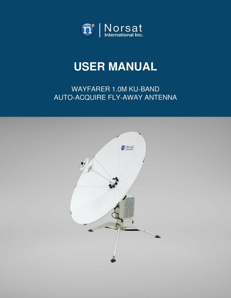
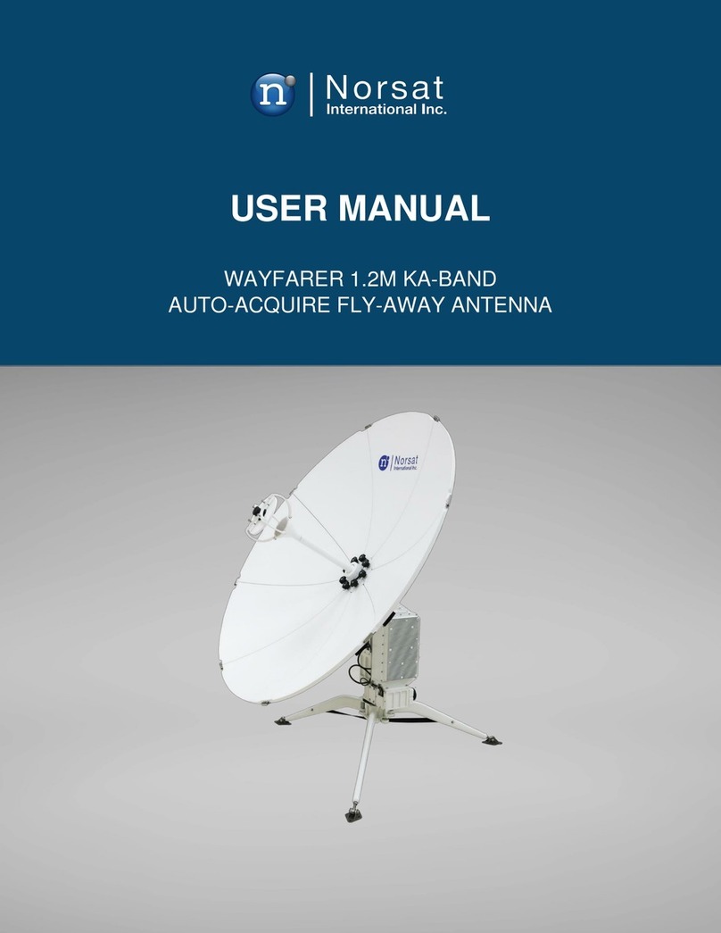
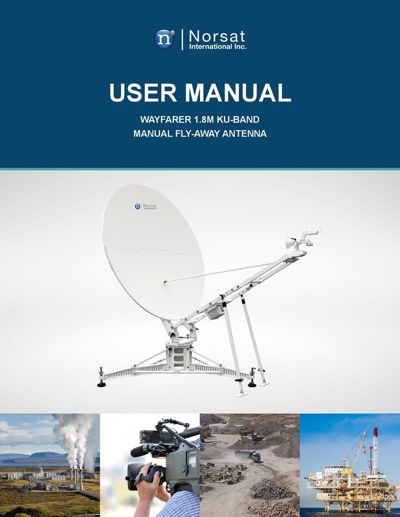
Norsat WAYFARER KU-BAND WFA120KU-EU User manual

WAYFARER 1.2M KU-BAND
AUTO-ACQUIRE FLY-AWAY ANTENNA
USER MANUAL


TABLE OF CONTENTS
Copyright Notice....................................................................................................................................... 4
Revision History........................................................................................................................................ 5
Cautions ................................................................................................................................................... 5
Acronyms.................................................................................................................................................. 5
List of Contents......................................................................................................................................... 6
Case 1 ...................................................................................................................................................... 6
Case 2 ...................................................................................................................................................... 7
1. Overview............................................................................................................................................... 8
1.1 Manual Contents ............................................................................................................................ 8
2. System Overview.................................................................................................................................. 8
2.1 System Block Diagram .................................................................................................................. 8
3. Hardware.............................................................................................................................................. 9
3.1 Antenna Dimensions ...................................................................................................................... 9
4. Electrical............................................................................................................................................... 11
4.1 Power Supply ................................................................................................................................. 12
4.2 Antenna Control Unit ...................................................................................................................... 12
4.3 Introduction to System Components .............................................................................................. 13
4.3.1Azimuth and Elevation Modules................................................................................................... 13
4.3.2 Polarization Module..................................................................................................................... 13
4.3.3 GPS Receiver ............................................................................................................................. 13
4.3.4 3D Compass/Inclinometer........................................................................................................... 13
4.3.5 Modem Port................................................................................................................................. 13
4.3.6 Adjustment Knobs ....................................................................................................................... 14
5. Quick Start............................................................................................................................................ 14
5.1 Antenna Assembly.......................................................................................................................... 14
5.2 Cable Connection........................................................................................................................... 17
5.3 Auto-Acquire through LinkControl (Non-OpenAMIP) ..................................................................... 18
5.4 Auto-Acquire through LinkControl (OpenAMIP) ............................................................................. 19
6. Software ............................................................................................................................................... 21
6.1 Minimum Recommended System Requirements .......................................................................... 21
6.1.1EthernetAdapterConguration................................................................................................... 21
6.2 Satellite Almanac............................................................................................................................ 26
6.3LinkProles..................................................................................................................................... 28
6.4 Status Monitoring ........................................................................................................................... 30
6.5 OpenAMIP vs Non-OpenAMIP Mode............................................................................................. 32
6.6 Auto-Acquisition (Non-OpenAMIP)................................................................................................. 32
6.7 Auto-Acquisition (OpenAMIP) ........................................................................................................ 33
6.8 Motor Control ................................................................................................................................. 35
7. System Troubleshooting....................................................................................................................... 37
8. System Maintenance............................................................................................................................ 39
9. Factory Reset ....................................................................................................................................... 39
10.TechnicalSpecications .................................................................................................................... 40
Appendix A - Magnetic declination Map ................................................................................................... 41
Appendix B - Default Antenna Settings .................................................................................................... 42
4
© 2020 Norsat International Incorporated (“Norsat”) All Rights Reserved DOC-000848 Rev A 10/2019
Copyright Notice
NOTICE: Norsat International Inc. (“Norsat”) assumes no responsibility for errors or omissions that may
appear in this publication. Norsat reserves the right to change this publication at any time, without notice.
Copyright © 2019. Norsat International Inc. All rights reserved.
All materials contained in this user guide are the property of Norsat International Inc. except as noted here below:
All materials in this user guide are protected by United States and international copyright laws. The
compilation of all content in this user guide is the exclusive property of Norsat.
RUGGED, ULTRA-
PORTABLE HIGH-
PERFORMANCE
SATELLITE TERMINALS
FOR COMMERCIAL
APPLICATIONS

5
© 2020 Norsat International Incorporated (“Norsat”) All Rights Reserved DOC-000848 Rev A 10/2019
REVISION DESCRIPTION Date YYYY/MM/DD
ARelease 2018/12/21
BLinkControl Software 2019/05/13
CUpdate Assembly Procedure 2019/08/26
DUpdate for LinkControl 2.0 Release
Fix minor formatting problems
2019/10/28
Revision History
Cautions
Acronyms
Antenna needs to be reset after powering up before Auto-Acquire.
Avoid exposing handheld device to direct sunlight.
Please avoid operation over hardware limit after turning off software limits.
Avoid heavy pressure or bumping onto the petal surface.
Ensure input power is 110 to 240VAC.
ACU Antenna Control Unit
AGC Antenna Gain Control
dAGC Antenna Gain Control for DVB signal strength
bAGC Antenna Gain Control for beacon signal strength
M&C Monitor and Control
IFL Interfacility Link
OMT Orthomode Transducer
LNB Low-noise Block Downconverter
BUC Block Upconverter
LO Local Oscillator
CCW Counter clockwise
CW Clockwise

6
© 2020 Norsat International Incorporated (“Norsat”) All Rights Reserved DOC-000848 Rev A 10/2019
List of Contents
NAME QUANTITY DESCRIPTION
Outdoor Unit 1 Antenna main pedestal with ACU
Hard Case 1 1 Hard case for pedestal, tripod
Hard Case 2 1 Hard case for feed horn, petals and power supply
Power supply 1 Antenna power supply accepting 100-240V AC input, 24V DC output
Compass sensor cable 1 Sensor cable for compass
Firmware upgrade cable 1 RS232(DB9)cableforACUrmwareupgrade
Remote Cable
Pedestal
Assembly
with BUC and
LNB
Modem Cable
Leg Assembly
Footpad x3
Antenna
Power Supply
Sensor Cable
Case 1

7
© 2020 Norsat International Incorporated (“Norsat”) All Rights Reserved DOC-000848 Rev A 10/2019
Feed Horn
Firmware
upgrade
cable
IFL cable
(optional)
BUC Power
Supply
(optional)
Petals
(5 to 8)
Petals
(1 to 4)
Case 2

8
© 2020 Norsat International Incorporated (“Norsat”) All Rights Reserved DOC-000848 Rev A 10/2019
1. Overview
The Norsat WAYFARER is an industrial strength transportable satellite communication system built strong for the
most demanding users working with the most challenging applications and environments. The WAYFARER is fully
automated,integrated,andversatileenoughfordeploymentvirtuallyanywhere,includingmobileeldofces,eld
vehicles, or directly on the ground. A complete satellite solution, the WAYFARER includes everything to meet your
communication needs.
1.1 Manual Contents:
The manual consists of 6 parts as shown below:
1. Overview of the manual and acronym list
2. System block diagram
3. Antenna dimensions and assembly
4. Antenna components and structure
5. Antenna software and user interface
6. Troubleshooting and maintenance
2. System Overview
The system consists of an antenna control unit, antenna drive unit, I/O unit, GPS module, beacon receiver, DVB
receiver, compass, inclinometer and other instruments.
2.1 System Block Diagram
OpenAMIP System Block Diagram: Non-OpenAMIP System Block Diagram:

9
© 2020 Norsat International Incorporated (“Norsat”) All Rights Reserved DOC-000848 Rev A 10/2019
3. Hardware
3.1 Antenna Dimensions
Ruggedized Pelican Case (iM 3075)
CASE NUMBER DIMENSIONS WEIGHT
Case 1 (Pedestal, Tripod) 846mm x 620mm x 490mm 34 Kg
Case 2 (Feed, Petal) 846mm x 620mm x 490mm 27Kg + accessories (up to 10 Kg)

10
© 2020 Norsat International Incorporated (“Norsat”) All Rights Reserved DOC-000848 Rev A 10/2019
Fiberboard Case
Side view of antenna after assembly when stowed (in: mm)
1200
1191.76
977
913
1242
848.82

11
© 2020 Norsat International Incorporated (“Norsat”) All Rights Reserved DOC-000848 Rev A 10/2019
Top view of antenna after assembly when stowed (in: mm)
Side view of antenna maximum height after assembly (in: mm)
4. Electrical
Antenna power supply Antenna is powered by a power supply that requires
110-240V AC input
LNB LNB is powered by 15V DC from ACU through Rx cable
BUC BUC up to 8W can be powered by 24V DC from modem through IFL cable
20W and 40W ATOM BUC requires 48V DC input from at least 300W power supply
1294.67

12
© 2020 Norsat International Incorporated (“Norsat”) All Rights Reserved DOC-000848 Rev A 10/2019
4.1 Power Supply
4.2 Antenna Control Unit
Antenna Control Unit is integrated with the pedestal
All ports and switches are installed onto the ACU, as shown below:
Port Name Description
Sensor Compasssignalinputfromcompassonreectorpetal#1
One Button One button control for antenna resetting, satellite pointing, stowing and stopping
motion without the handheld device
1. Press button and release after one beep, antenna will reset and verify limit switches
2. Press button and release after two beeps, antenna will start pointing to the last
satellite it has successfully acquired
3. Press button and release after three beeps, antenna will stow
Remote RJ45 ethernet port for LinkControl Client
Modem RJ45 port for modem
On/Off Power switch for antenna
Rx Rx signal output from LNB
Tx Tx signal input for BUC
DC IN 24V DC power input, to be connected to supplied AC power adapter

13
© 2020 Norsat International Incorporated (“Norsat”) All Rights Reserved DOC-000848 Rev A 10/2019
4.3 Introduction to System Components
4.3.1 Azimuth and Elevation Modules
Azimuth module consists of: azimuth motor, planetary gearbox, worm gearbox, internal gear and azimuth base. The
azimuth movement is mechanically self-locking and can be manually controlled through the lower knob on pedestal
Elevation module consists of: Elevation motor, elevation gearbox and elevation base. The motor incorporates
electromagnetic braking. Thus, the elevation angle can be maintained in case of power outage. The elevation angle
can be manually controlled through the upper knob on pedestal.
4.3.2 Polarization Module
The polarization module consists of polarization motor, feed assembly, gearbox, duplexer, lter and LNB. The
polarization module’s main functionality is to adjust the polarization angle and isolate the Tx/Rx signal.
The installation of polarization module is optimized from factory to ensure best performance. Should the polarization
module be removed, please mark the location of mounting screws on the slot beforehand.
4.3.3 GPS Receiver
GPS module is installed inside the ACU.
GPS lock/ not locked indicator can be observed through the plastic cap on top of the ACU. When the indicator is
blinking, the GPS is not locked and when indicator is on, the GPS is locked.
GPS Lock/ Not locked and latitude and longitude information are showing in real time LinkControl.
4.3.4 3D Compass/Inclinometer
Thecompass/inclinometerismountedontothereectorpetal1.Thedeviceprovidesheadingandelevationangle
to ACU. The heading information is updated upon system reset.
4.3.5 Modem Port
The modem port is designed to be integrated with iDirect Modems. The ACU outputs the GPS signal

14
© 2020 Norsat International Incorporated (“Norsat”) All Rights Reserved DOC-000848 Rev A 10/2019
4.3.6 Adjustment Knobs
Adjustment knobs for Azimuth and Elevation are
available on the antenna for use in case of emergency.
Please follow the procedure below to nish a typical
satellite acquisition.
5.1 Antenna Assembly
Theyawayterminalrequiresassemblybeforeuse.The
procedure is as follows:
1) Pull out the tripod from Case 1, unfold the legs to
limit and buckle up the strap so that the legs are sturdy.
You will notice a metal latch on the side of the tripod.
Ensure thus latch is pulled upwards securely before the
next assembly step.
You may want to stake down or add ballast weight to the
tripod legs in a high wind condition.
Mount footpads after setting up tripod:
1. Take footpads from
Case 1
2. Insert leg joint into
footpad from top
3. Push button on quick
release pin to insert from
side
4. Ensure the spring pin
goes through mounting
hole
Latch
Strap
Tripod
5. Quick Start

15
© 2020 Norsat International Incorporated (“Norsat”) All Rights Reserved DOC-000848 Rev A 10/2019
2) Take out the pedestal from case 1. The thumbscrews
and handle should be facing upwards while the azimuth
connector should be downwards. Find and hold onto
the handle at the top of the pedestal. Insert the azimuth
connector into the tripod center.
3)Ensurethepedestalsitsatontothetripod.Adjustthe
orientation so that front (as indicated with 3D arrow on the
top of the pedestal) points to the satellite belt.
Push down the latch and ensure the pedestal is locked
to tripod.
Ensure the BUC and LNB are mounted and connected
to waveguide. Remove the cover on the feed mount.
Thumbscrews
Azimuth
Connector
Feed Cover
Feed Collar
Slot Locating Pin
Handle
4) Take out the feed assembly from case 2 and hold the feed collar. Remove the feed cover by rotating
counterclockwise. When the cover is removed, you will notice a small indented slot near the waveguide opening.
Remove feed mount cover from top of pedestal. Align the locating pin from feed mount to the indented slot on feed,
then assemble feed to feed mount by tightening the feed collar clockwise. At this stage, your assembled terminal
should look like what is displayed in Figure A:
Figure A

16
© 2020 Norsat International Incorporated (“Norsat”) All Rights Reserved DOC-000848 Rev A 10/2019
5) Unpack the WAYFARER petals from case 2. You
will notice numbers behind the petal, arrange the
petals in ascending numerical order starting from “1”.
On the pedestal, locate the “1” label – this indicates
the installation location for petal 1.
Begin Installing petal 1 by inserting it into the thumb
screw.Lockdownreectorpetalbyrotatingthethumb
screw clockwise. Repeat the mounting procedure in
sequence for petal 2 to 8.
6) During the petal assembly, ensure to latch the tips of sequential petals securely after installation:
1. Ensure mating latches
have same serial ID
2. Push in the center
pin with metal handle
parallel to top surface.
The latch will be facing
the ground.
3. Rotate latch 90
degrees perpendicular to
top surface
4. Fold down latch to
top surface and secure
it so that petals are
connected to each other.
7) Your assembled WAYFARER is now ready for cable connection and should appear as seen below:
Latch
Top Surface
Petal 1 Thumb Screw

17
© 2020 Norsat International Incorporated (“Norsat”) All Rights Reserved DOC-000848 Rev A 10/2019
5.2 Cable Connection
1) Connect cables according to the table below:
SIGNAL ACU PORT TO CABLE
DC power input DC IN Power supply Power supply DC cable
Compass data SENSOR Compass on petal Sensor cable
Tx signal Tx Modem Tx port Tx cable (red end)
Rx signal Rx Modem Rx port Rx cable (green end)
GPS data MODEM Modem Console port Modem cable
Remote Control REMOTE Controller Laptop Remote cable
2) Connect power supply to AC power source with 100-240VAC.
Connection Diagram OpenAMIP Modem:
Connection Diagram Non-OpenAMIP Modem:

18
© 2020 Norsat International Incorporated (“Norsat”) All Rights Reserved DOC-000848 Rev A 10/2019
5.3 Auto-Acquire through LinkControl (Non-OpenAMIP)
Once the antenna is powered on
and connected to the computer,
open LinkControl.exe
Wait for all indicators to show up as
ok from the Start page to show up
as “OK” or “N/A”
Click LinkProles navigation
button and ensure an OpenAMIP
LinkProle prole has been
applied. See Section 6.2 and 6.3
for how to set Satellite Almanac and
LinkProle.
Select and then apply LinkProle
if an OpenAMIP LinkProle is not
already active
Click Auto-Acquire navigation button.
Click Start Auto-Acquire and
antenna will start auto-acquisition
with pre-set signal level threshold
and signal magnication.
1
2
3
Note: The BUC requires a 10 MHz reference in order to transmit.
Monitor the actual signal level reading reported while the antenna is auto-acquiring.
-Ifthesignallevelreadingissaturatedat9.99Vtheusermaylowerthemagnicationtoavoidunoptimizedpointing.
- If signal level reading is below the threshold during pointing, the user may lower the signal level threshold or raise the
magnicationtoavoidfailureinpointing.
Once Pointing is completed, system status will show as Auto-Acquire completed.

19
© 2020 Norsat International Incorporated (“Norsat”) All Rights Reserved DOC-000848 Rev A 10/2019
5.4 Auto-Acquire through LinkControl (OpenAMIP)
Once the antenna and modem are
powered on and connected to the
computer, open LinkControl.exe
Wait for all indicators on the Start
page to show up as “OK” or “N/A”
Click LinkProles navigation
button and ensure an OpenAMIP
LinkProleprolehasbeenapplied.
See Section 6.2 and 6.3 for how to
setSatelliteAlmanacandLinkProle.
Select and then apply LinkProle
if an OpenAMIP LinkProle is
notalready active
Once the system is ready, the
OpenAMIP modem will attempt to
initiate an auto-acquire.
Select Proceed to allow the auto-
acquire to initiate.
Select Abort to prevent the auto-
acquire from initiating and to place
the Antenna in User Controlled
Mode (Refer to Auto-Acquisition
(Non-OpenAMIP) for more details)
1
2
3

20
© 2020 Norsat International Incorporated (“Norsat”) All Rights Reserved DOC-000848 Rev A 10/2019
Monitor the actual signal level
reading reported while the antenna
is auto-acquiring.
If desired, navigate to the Modem
page to get information on the
current modem parameters
- If the signal level reading is saturated at 9.99V the user may lower the magnication to avoid unoptimized
pointing.
- If signal level reading is below the threshold during pointing, the user may lower the signal level threshold or raise
themagnicationtoavoidfailureinpointing.
4
5
This manual suits for next models
1
Table of contents
Other Norsat Antenna manuals

Norsat
Norsat Wayfarer User manual

Norsat
Norsat Wayfarer User manual

Norsat
Norsat Wayfarer User manual

Norsat
Norsat WAYFARER 1.2M KA-BAND User manual

Norsat
Norsat WFM180KU User manual

Norsat
Norsat WAYFARER 1.0M KU-BAND User manual

Norsat
Norsat Wayfarer User manual

Norsat
Norsat WAYFARER WFM090KU-RC User manual

Norsat
Norsat Sinclair StealthWave SHA211 User manual

Norsat
Norsat GLOBETrekker User manual