Shure PA411-E User manual

PA411
Antenna Combiner
Th Shure antenna combiner, PA411, user guide.
Version: 1.1 (2020-I)

Shure Incorporated
2/11
Table of Contents
PA411 Antenna Combiner 3
Important Product Information 3
IMPORTANT SAFETY INSTRUCTIONS 3
SAFETY PRECAUTIONS 4
General Description 4
Included Components 5
Front and Rear Panels 5
Power and RF Connections 6
Optional Accessories and Replacement Parts 8
Specifications 9
LICENSING INFORMATION 10
Certifications 11

Shure Incorporated
3/11
1.
2.
3.
4.
5.
6.
7.
8.
9.
10.
11.
12.
13.
14.
15.
16.
17.
18.
19.
20.
21.
PA411
Antenna Combiner
Important Product Information
IMPORTANT SAFETY INSTRUCTIONS
READ these instructions.
KEEP these instructions.
HEED all warnings.
FOLLOW all instructions.
DO NOT use this apparatus near water.
CLEAN ONLY with dry cloth.
DO NOT block any ventilation openings. Allow sufficient distances for adequate ventilation and install in accordance
withthemanufacturer’sinstructions.
DONOTinstallnearanyheatsourcessuchasopenflames,radiators,heatregisters,stoves,orotherapparatus(in
cluding amplifiers) that produce heat. Do not place any open flame sources on the product.
DO NOT defeat the safety purpose of the polarized or grounding type plug. A polarized plug has two blades with one
wider than the other. A grounding type plug has two blades and a third grounding prong. The wider blade or the third
prongareprovidedforyoursafety.Iftheprovidedplugdoesnotfitintoyouroutlet,consultanelectricianforreplace
ment of the obsolete outlet.
PROTECT the power cord from being walked on or pinched, particularly at plugs, convenience receptacles, and the
point where they exit from the apparatus.
ONLY USE attachments/accessories specified by the manufacturer.
USE only with a cart, stand, tripod, bracket, or table specified by the manufacturer, or sold with the apparatus. When a
cart is used, use caution when moving the cart/apparatus combination to avoid injury from tip-over.
UNPLUG this apparatus during lightning storms or when unused for long periods of time.
REFER all servicing to qualified service personnel. Servicing is required when the apparatus has been damaged in any
way, such as power supply cord or plug is damaged, liquid has been spilled or objects have fallen into the apparatus,
the apparatus has been exposed to rain or moisture, does not operate normally, or has been dropped.
DO NOT expose the apparatus to dripping and splashing. DO NOT put objects filled with liquids, such as vases, on the
apparatus.
The MAINS plug or an appliance coupler shall remain readily operable.
The airborne noise of the Apparatus does not exceed 70dB (A).
ApparatuswithCLASSIconstructionshallbeconnectedtoaMAINSsocketoutletwithaprotectiveearthingconnec
tion.
To reduce the risk of fire or electric shock, do not expose this apparatus to rain or moisture.
Do not attempt to modify this product. Doing so could result in personal injury and/or product failure.
Operate this product within its specified operating temperature range.
Shure Incorporated
4/11
•
•
•
•
•
低功率電波輻射性電機管理辦法
第十二條
經型式認證合格之低功率射頻電機,非經許可,公司、商號或使用者均不得擅自變更頻率、加大功率或變更原設計之特性及功
能。第十四條
低功率射頻電機之使用不得影響飛航安全及干擾合法通信;經發現有干擾現象時,應立即停用,並改善至無干擾時方得繼續使
用。前項合法通信,指依電信法規定作業之無線電通信。低功率射頻電機須忍受合法通信或工業、科學及醫療用電波輻射性電機
設備之干擾。
SAFETY PRECAUTIONS
Thepossibleresultsofincorrectusearemarkedbyoneofthetwosymbols—"WARNING"and"CAUTION"—dependingonthe
imminence of the danger and the severity of the damage.
WARNING: Ignoring these warnings may cause severe injury or death as a result of incorrect operation.
CAUTION:Ignoringthesecautionsmaycausemoderateinjuryorpropertydamageasaresultofincor
rect operation.
CAUTION
Never disassemble or modify the device, as failures may result.
Do not subject to extreme force and do not pull on the cable or failures may result.
Keep the product dry and avoid exposure to extreme temperatures and humidity.
WARNING
If water or other foreign objects enter the inside of the device, fire or electric shock may result.
Do not attempt to modify this product. Doing so could result in personal injury and/or product failure.
Thisdeviceisabletoproducesoundvolumehigherthan85dBSPL.Pleasecheckyourmaximumallowedcontinuousnoiseexposurelevelbasedonyourna
tional employment protection requirements.
WARNING
LISTENING TO AUDIO AT EXCESSIVE VOLUMES CAN CAUSE PERMANENT HEARING DAMAGE. USE AS LOW A VOL
UME AS POSSIBLE. Over exposure to excessive sound levels can damage your ears resulting in permanent noise-induced
hearing loss (NIHL). Please use the following guidelines established by the Occupational Safety Health Administration (OSHA)
on maximum time exposure to sound pressure levels before hearing damage occurs.
90 dB SPL
at 8 hours
95 dB SPL
at 4 hours
100 dB SPL
at 2 hours
105 dB SPL
at 1 hour
110 dB SPL
at ½ hour
115 dB SPL
at 15 minutes
120 dB SPL
Avoid or damage may occur
General Description
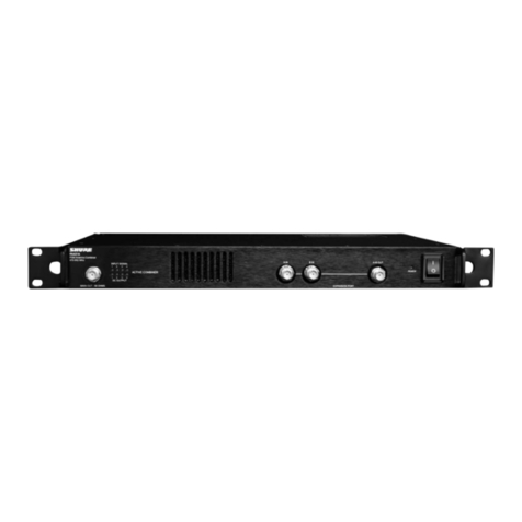
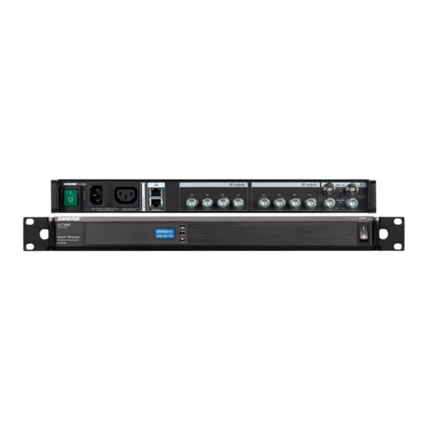
The Shure PA411 Antenna Combiner distributes DC power and RF signal for up to four Shure PSM 300transmitters.Thecom
pact half-rack system significantly reduces the amount of antennas and power supplies needed when using multiple systems.
®

Shure Incorporated
5/11
•
•
•
•
•
•
Included Components
(1) PA411 Antenna Combiner
(1) 1-to-4 Power Distribution Cable
(1) PS60 Power Supply
(1) Rack Mounting Kit
(1) BNC Bulkhead Adapter
(4) 22-inch BNC-BNC Coaxial Cables
Note: Antenna is not included. Please use the antenna that shipped with the PSM transmitters or other antenna from the appropriate frequency range.
Front and Rear Panels
①RF Output Antenna
Connector
Use the ¼ wave antenna supplied with the P3T transmitter, or any other Shure antennas that
cover 470-865 MHz
②RF LED Indicators Green : RF signal present
Red: RF signal overload
③Power LED Green : Power on
Green/red flashing: Power output overload
④Power Switch
⑤Power Input Requires a Shure PS60 power supply

Shure Incorporated
6/11
1.
2.
3.
4.
5.
⑥Power Output Requires a Shure PS411-PC power distribution cable to deliver power to transmitters
⑦RF Inputs Connect to transmitter RF outputs
Power and RF Connections
Connect the Shure PS60 power supply to a power outlet and to the power input on the PA411.
Connect the 1-to-4 power cable to the DC power output on the PA411.
Connect a power terminal from the 1-to-4 power cable to each P3T transmitter power input.
Connect an antenna to the P3T antenna output on the front panel. Acceptable antennas include the ¼-wave antenna
supplied with the P3T transmitter or any Shure antennas that cover 470-865 MHz.
Connect each P3T antenna output to an antenna input on the PA411, using BNC coaxial cable.

Shure Incorporated
7/11

Shure Incorporated
8/11
Optional Accessories and Replacement Parts
1-to-4 Power Distribution Cable PS411-PC
22 in. BNC-BNC Coaxial Cable 95K2035
2 ft. BNC-BNC Coaxial Cable UA802
6 foot (1.8m) BNC to BNC Coaxial Cable for Remote Antenna Mounting for ULX
Wireless System UA806
25 ft. BNC-BNC Coaxial Cable UA825
50 ft. BNC-BNC Coaxial Cable UA850
100 ft. BNC-BNC Coaxial Cable UA8100
Power supply PS45
Bulkhead Adapter 95A8994
1/4 Wave Antenna (748–865 MHz) for SLX Wireless System UA400
1/4 wave antenna (470-752 MHz) UA400B
1/2 wave antenna (470-530 MHz) UA8-470-530
1/2 wave antenna (500-560 MHz) UA8-500-560
1/2 wave antenna (518-578 MHz) UA8-518-578
1/2 wave antenna (518-582 MHz) UA8-518-582
1/2 wave antenna (518-598 MHz) UA8-518-598
1/2 wave antenna (554-590 MHz) UA8-554-590
1/2 wave antenna (554-626 MHz) UA8-554-626
1/2 wave antenna (554-638 MHz) UA8-554-638
1/2 wave antenna (578-638 MHz) UA8-578-638
1/2 wave antenna (596-668 MHz) UA8-596-668
1/2 wave antenna (596-698 MHz) UA8-596-698
1/2 wave antenna (596-714 MHz) UA8-596-714
1/2 wave antenna (600-666 MHz) UA8-600-666
1/2 wave antenna (626-698 MHz) UA8-626-698
1/2 wave antenna (638-698 MHz) UA8-638-698
1/2 wave antenna (670-742 MHz) UA8-670-742

Shure Incorporated
9/11
1/2 wave antenna (710-790 MHz) UA8-710-790
1/2 wave antenna (740-814 MHz) UA8-740-814
1/2 wave antenna (750-822 MHz) UA8-750-822
1/2 wave antenna (774-865 MHz) UA8-774-865
Single Rack Mount Kit RPW503
Dual Rack Mount Kit RPW504
Specifications
Power Requirements
15V DC
DC Output
12V DC (x4)
Output Current
Combined total from all DC outputs
1.4 A, maximum
Operating Temperature Range
−18°C to 63°C
Dimensions
42 x 198 x 177mm (H x W x D)
Net Weight
1.32kg(2.9lbs)
RF Input
Connector Type
BNC
RF Frequency Range
470 to 865MHz
Maximum Input Level
20dBm Per Channel
Input Port Isolation
50dB, typical
RF Input Power
Operating Range,Per Channel

Shure Incorporated
10/11
1.
2.
4.5 to 15dBm
LED Indicator Minimum Detection Threshold
3dBm ±1.5dB
RF Overload LED Threshold
17.5dBm ±1dB
Impedance
50Ω
RF Output
RF Frequency Range
470 to 865MHz
Output Intercept Point (OIP3)
48dBm, typical
Connector Type
BNC
Impedance
50Ω
Reverse Isolation
Ouput to Input
40dB, typical
Gain
Input to any output port
−5 to 0dB
LICENSING INFORMATION
Licensing: A ministerial license to operate this equipment may be required in certain areas. Consult your national authority for
possible requirements. Changes or modifications not expressly approved by Shure Incorporated could void your authority to
operatetheequipment.LicensingofShurewirelessmicrophoneequipmentistheuser’sresponsibility,andlicensabilityde
pendsontheuser’sclassificationandapplication,andontheselectedfrequency.Shurestronglyurgestheusertocontactthe
appropriate telecommunications authority concerning proper licensing, and before choosing and ordering frequencies.
Thisdevicecontainslicenceexempttransmitter(s)/receiver(s)thatcomplywithInnovation,ScienceandEconomicDevelop
mentCanada’slicenceexemptRSS(s).Operationissubjecttothefollowingtwoconditions:
This device may not cause interference.
This device must accept any interference, including interference that may cause undesired operation of the device.

Shure Incorporated
11/11
1.
2.
•
•
•
•
•
L’émetteur/récepteurexemptdelicencecontenudansleprésentappareilestconformeauxCNRd’Innovation,Scienceset
DéveloppementéconomiqueCanadaapplicablesauxappareilsradioexemptsdelicence.L’exploitationestautoriséeauxdeux
conditions suivantes :
L’appareilnedoitpasproduiredebrouillage;
L’appareildoitacceptertoutbrouillageradioélectriquesubi,mêmesilebrouillageestsusceptibled’encompromettrele
fonctionnement.
Federal Communications Commission RF Exposure Notice:
Antennas used for the purpose of radiating signals are limited to a maximum gain of 14 dBi. Each antenna must be positioned
to observe minimum separation requirements from all users and bystanders. The following guidelines should be used when
considering separation distances.
Antennas must be placed such that, under normal conditions, personnel cannot come within 72 cm (~2.5 ft.) from any antenna.
Adhering to this minimum separation will ensure that the employee or bystander cannot exceed RF exposures beyond the
maximum permissible limit as defined by 47 CFR 1.1310, i.e., limits for General Population/Uncontrolled Exposure.
Certifications
Meets essential requirements of the following European Directives:
Low Voltage Directive 2006/95/EC
Conforms to the relevant requirements of regulation (EC) No.278/2009, for low voltage external power supplies.
R&TTE Directive 99/5/EC
Conforms to European Regulation (EC) No. 1275/2008, as amended.
WEEE Directive 2012/19/EU, as amended by 2008/34/EC
RoHS Directive EU 2015/863
Note: Please follow your regional recycling scheme for batteries and electronic waste
Meets requirements of the following standards:
EN 300 422 Parts 1 and 2
EN 301 489 Parts 1 and 9
Certified under FCC Part 74.
Certified by ISED in Canada under RSS-123 and RSS-102.
FCC ID: DD4PA411A. IC: 616A-PA411A.
The CE Declaration of Conformity can be obtained from Shure Incorporated or any of its European representatives. For contact
information please visit www.shure.com
The CE Declaration of Conformity can be obtained from: www.shure.com/europe/compliance
Authorized European representative:
Shure Europe GmbH
Headquarters Europe, Middle East & Africa
Department: EMEA Approval
Jakob-Dieffenbacher-Str. 12
75031 Eppingen, Germany
Phone: +49-7262-92 49 0
Fax: +49-7262-92 49 11 4
This manual suits for next models
1
Table of contents
Other Shure Antenna manuals
Popular Antenna manuals by other brands

Philex
Philex DigiTop 27768RG user guide

Strong
Strong SRT ANT 12 ECO user manual

CommScope
CommScope Valuline installation instructions

Mosley
Mosley S-402-M Assembly instructions

TRENDnet
TRENDnet TEW-AI75OB - 11a/g 7/5dBi Indoor Omni Directional... Specifications

TE Connectivity
TE Connectivity WMM8G-7-38 Installation Guide and Safety Information