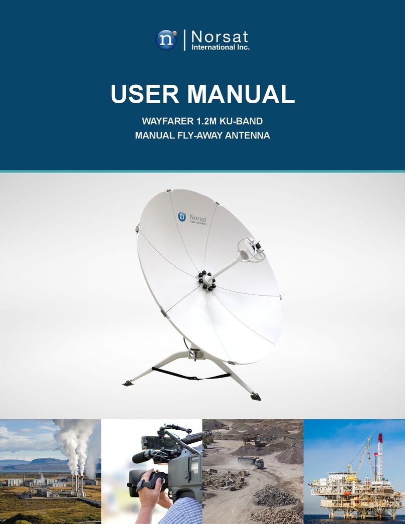
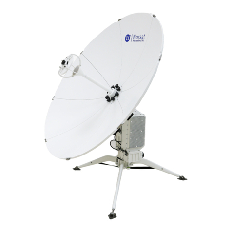
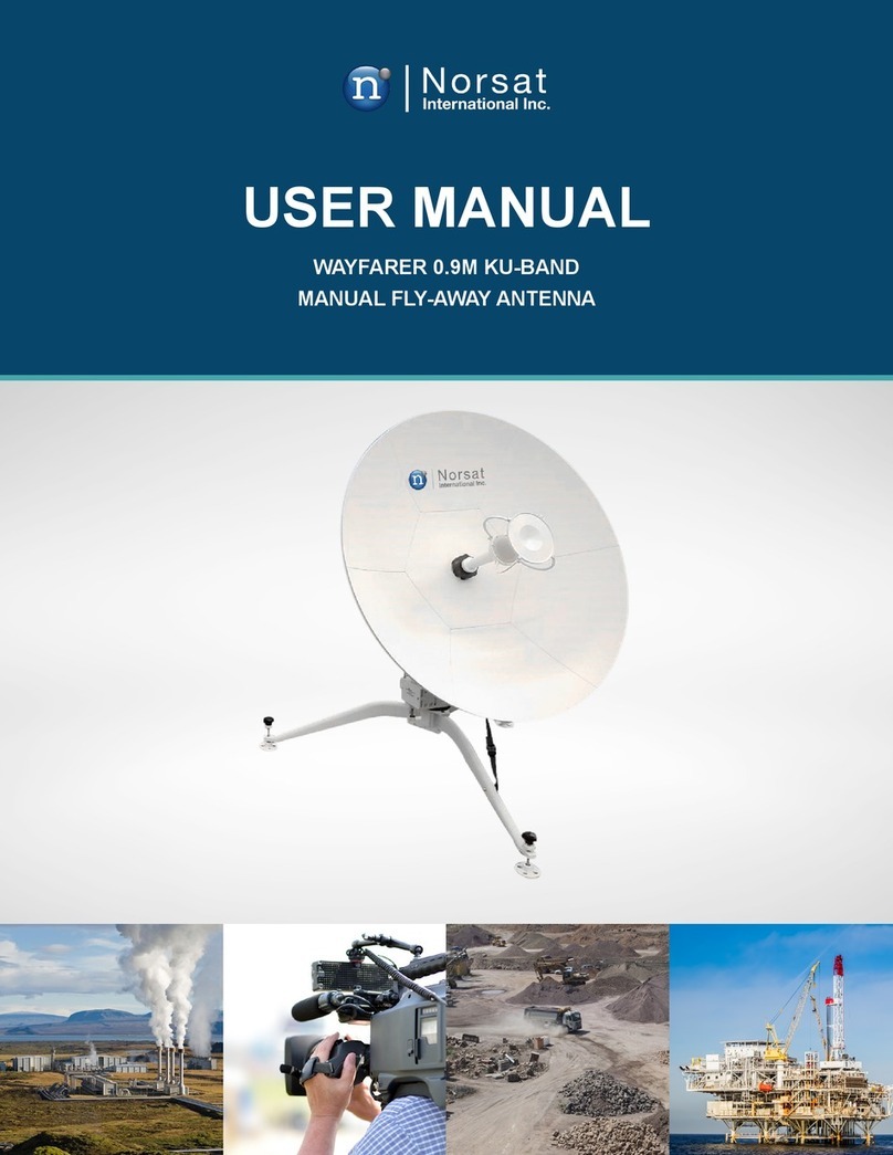
Norsat Wayfarer User manual

TROUBLESHOOTING GUIDE
WAYFARER 1.2M KU-BAND
MANUAL DRIVE AWAY ANTENNA

© Norsat International Inc. (“Norsat”) All Rights Reserved
YYYY-MM-DD DOC# Rev 2
TABLE OF CONTENTS
Contents
TROUBLESHOOTING GUIDE................................................................................................... 1
WAYFARER 1.2M KU-BAND MANUAL DRIVE AWAY ANTENNA............................................ 1
TABLE OF CONTENTS............................................................................................................. 2
1. Overview................................................................................................................................ 3
1.1 System Overview ............................................................................................................. 3
2 Antenna Components ............................................................................................................. 5
2.1 Outdoor Unit..................................................................................................................... 5
2.2 Turntable (Azimuth and Elevation) ................................................................................... 6
2.3 Feed Assembly ................................................................................................................ 6
2.4 GPS Receiver .................................................................................................................. 7
2.5 3D Compass .................................................................................................................... 7
2.6 Hand Crank...................................................................................................................... 8
2.7 Indoor Unit ACU............................................................................................................... 9
3 System Troubleshooting ........................................................................................................10
4 System Maintenance..............................................................................................................13
5 Technical Specifications.........................................................................................................14
................................................................................................ Error! Bookmark not defined.

© Norsat International Inc. (“Norsat”) All Rights Reserved
YYYY-MM-DD DOC# Rev 3
1. Overview
The Norsat Wayfarer is an industrial strength transportable satellite communication system built
strong for the most demanding users working with the most challenging applications and
environments. The Wayfarer is fully automated, integrated, and versatile enough for deployment
virtually anywhere, including mobile field offices, field vehicles, or directly on the ground. A
complete satellite solution, the Wayfarer includes everything to meet your communication needs.
1.1 System Overview
System consists of antenna feedback system, servo mechanism and control system.
Antenna feedback system is the core of the system and consists of reflector, feed horn, LNB,
BUC, OMT and waveguides etc.
Servo mechanism consists of gears, timing belt, gear box, worm gear
Control system has two parts:
•Outdoor unit: Motor driver.
•Indoor unit: ACU controller.

© Norsat International Inc. (“Norsat”) All Rights Reserved
YYYY-MM-DD DOC# Rev 4
Motor driver of outdoor unit connects to ACU controller through RS-422 M&C cable.

© Norsat International Inc. (“Norsat”) All Rights Reserved
YYYY-MM-DD DOC# Rev 5
2. Antenna Components
2.1 Outdoor Unit
1-Reflector 2-Feed 3-Turntable 4-Boom arm 5-Roof Mount 6-Controller Box

© Norsat International Inc. (“Norsat”) All Rights Reserved
YYYY-MM-DD DOC# Rev 6
2.2 Turntable (Azimuth and Elevation)
Turntable consists of two main structures: Azimuth module and Elevation module
Azimuth module: Azimuth motor, planetary gearbox and worm gear. The Azimuth transmission is
self-locking in case of power loss.
Elevation module: Elevation motor, planetary gearbox and worm gear. The Elevation transmission
is self-locking in case of power loss.
1-Elevation worm gear 2-Elevation motor 3-Azimuth motor 4-Azimuth worm gear
2.3 Feed Assembly
Polarization modules consist of polarization motor, feed, polarization transmission gear, OMT,
filter and LNB. It can adjust polarization angle and isolate Tx/Rx signals.
The installation location of feed assembly onto boom arm is adjusted in factory. In case of
maintenance, please mark the locations of the feed assembly so that it can be re-installed into
same location.

© Norsat International Inc. (“Norsat”) All Rights Reserved
YYYY-MM-DD DOC# Rev 7
1-Feed horn 2-OMT 3-LNB 4-Rotary Joint
2.4 GPS Receiver
GPS is installed on the side of the antenna turntable. It collects the latitude and longitude of the
current location for use of ACU and external Modem
GPS transmits lat/log information through serial connection. In order to check the working
condition of the GPS, the enclosure needs to be removed and the indicator lights can be read as
below:
-Indicator blinking: GPS searching signal
-Indicator on: GPS has locked
GPS needs to be locked in auto-acquire when used in a different location than last operation.
2.5 3D Compass
GPS
location

© Norsat International Inc. (“Norsat”) All Rights Reserved
YYYY-MM-DD DOC# Rev 8
3D compass is mounted on back of the reflector to reflect the real time heading, pitch and roll
information.
The compass is calibrated from factory and can provide accurate heading information with hard
iron and soft iron compensation.
Position data is transmitted to antenna through serial connection. The antenna control unit reads
the heading information upon antenna reset and heading information is used for auto-acquire.
Removing two pan head screws and the enclosure gives access to the 3D compass for
maintenance purpose.
2.6 Hand Crank
Hand crank is used to manually drive the antenna in case of emergency.
Do not use hand crank when antenna is powered on
1-Elevation crank 2-Azimuth crank
Back of Reflector
3D compass

© Norsat International Inc. (“Norsat”) All Rights Reserved
YYYY-MM-DD DOC# Rev 9
2.7 Indoor Unit ACU
Indoor Unit ACU is a 1RU rack mount unit which includes power supply, microcontroller with
screen and control buttons, On/Off switch, beacon receiver, DVB receiver, Wifi module and fans.

© Norsat International Inc. (“Norsat”) All Rights Reserved
YYYY-MM-DD DOC# Rev 10
3. System Troubleshooting
Error codes are identified from INFO –Alarm from Indoor Unit ACU or State info page from
Android app. User may use the troubleshooting information to identify the issue and contact
manufacturer when necessary.
Code
Description
Troubleshooting
E0
Azimuth drive exception
Check connection of motor control and power
cables
Check whether the Azimuth drive is jammed or
overloaded
System reboot is required after troubleshooting
Contact manufacturer if alarm remains after reboot
E1
Elevation drive exception
Check connection of motor control and power
cables
Check whether the Elevation drive is jammed or
overloaded
System reboot is required after troubleshooting
Contact manufacturer if alarm remains after reboot
E2
Polarization drive exception
Check connection of motor control and power
cables
Check whether the Polarization drive is jammed or
overloaded
System reboot is required after troubleshooting
Contact manufacturer if alarm remains after reboot
E3
GPS not connected
Check M&C and power cable connection from
antenna to ACU
Restore to factory settings
System reboot is required after troubleshooting
Contact manufacturer if alarm remains after reboot
E4
Compass not connected
Check M&C and power cable connection from
antenna to ACU
Restore to factory settings
System reboot is required after troubleshooting
Contact manufacturer if alarm remains after reboot
E5
Beacon receiver not connected
Check cable connection inside ACU for Beacon
receiver
System reboot is required after troubleshooting
Contact manufacturer if alarm remains after reboot
E6
DVB receiver not connected
Check cable connection inside ACU for DVB
receiver
System reboot is required after troubleshooting
Contact manufacturer if alarm remains after reboot
E7
Polarization zeroing failure
Check whether the polarization limit switch is
functional
Check whether the polarization drive is jammed on
range of motion
System reboot is required after troubleshooting

© Norsat International Inc. (“Norsat”) All Rights Reserved
YYYY-MM-DD DOC# Rev 11
Contact manufacturer if alarm remains after reboot
E8
Azimuth zeroing failure
Manually Stow antenna and reboot system
Check whether Azimuth limit switch is functional
Contact manufacturer if alarm remains
W1
GPS not locked
Wait for a couple minutes to capture GPS signal
Ensure sight to GPS satellites
E9
CAN communication exception
Check M&C and power cable connection from
antenna to ACU
W2
Limited Elevation motion
Move elevation away from limit
E10
Azimuth Tracking Error
Contact manufacturer
E11
Elevation Tracking Error
Contact manufacturer
E12
Data out of Bounds 1
Check the targeted satellite information entered is
correct and satellite is within sight
Check latitude and longitude settings
Check antenna calibration is within reasonable
range from user manual
Check azimuth angle is within reasonable range
from user manual
E13
Data out of Bounds 2
Check GPS coordinates entered manually is
correct
E14
Hardware Error 1
Restore factory settings
Contact manufacturer if alarm remains after reboot
E15
Reset antenna angles
Stow antenna manually
Check readings from compass
Check Azimuth, Elevation and Polarization motions
System reboot is required after troubleshooting
E16
Limit switch error
Check M&C and power cable connection from
antenna to ACU
Check limit switch functionality
E17
Communication exception
Check M&C and power cable connection from
antenna to ACU
Contact manufacturer

© Norsat International Inc. (“Norsat”) All Rights Reserved
YYYY-MM-DD DOC# Rev 12
E18
Stow error
Check M&C and power cable connection from
antenna to ACU
Check limit switch functionality

© Norsat International Inc. (“Norsat”) All Rights Reserved
YYYY-MM-DD DOC# Rev 13
4. System Maintenance
Regular maintenance is recommended per the schedule below:
No.
Description
Frequency
1
Inspect and clean integrity of feed horn cover, replace
when damaged
Once per month
2
Inspect OMT and waveguide sealing, if there is a leakage,
dry out the components and seal with RTV or replace
damaged parts.
Once per month
3
Inspect screws and nuts, tighten or replace screws upon
loosening or rusting
Once per month
4
Inspect system for any noise during operation, clean up
the transmission and lubricate when necessary
Once per month
5
Inspect paint integrity of the antenna, touch up when
Once per month
6
Inspect wear and tear of timing belt and lubricate gears
and transmissions. Replace
Once per year
7
Calibrate compass to ensure correct heading
Once per year
8
Clean the reflector surface
Every 3 months

© Norsat International Inc. (“Norsat”) All Rights Reserved
YYYY-MM-DD DOC# Rev 14
5. Technical Specifications
Reflector aperture
1.2m
Reflector type
Offset
Tx frequency
13.75~14.5 GHz
Rx frequency
10.95~12.75 GHz
Tx gain
42.6+20lg(f/14.25) dBi
Rx gain
41.5+20lg(f/12.5) dBi
Polarization feature
Linear
Cross polarization
≥35 dB (Axial)
Rx/Tx isolation
Rx≥40dB Tx≥85 dB
Sidelobe
≤-14 dB (first side lobe)
Weight
≤85 Kg
Stowed size
1760mm×1210mm×420mm (length×width×height)
Slewing
area
Azimuth
± 200°
Elevation
10°~90°
Polarization
± 90°
Rotate
speed
Azimuth
0.1° /S ~6° /S
Elevation
0. 1° /S ~6° /S
Pol
0. 1° /S ~6° /S
Work wind load
20m/s
Survival wind load
25m/s
Temperature
-40℃~+55℃(outdoor); -20℃~+55℃(indoor)
Humidity
5-95%
Other manuals for Wayfarer
3
Table of contents
Other Norsat Antenna manuals

Norsat
Norsat GLOBETrekker User manual

Norsat
Norsat WAYFARER KU-BAND WFA120KU-EU User manual

Norsat
Norsat Sinclair StealthWave SHA211 User manual

Norsat
Norsat Wayfarer User manual

Norsat
Norsat Wayfarer User manual

Norsat
Norsat WAYFARER 1.0M KU-BAND User manual

Norsat
Norsat WFM180KU User manual

Norsat
Norsat WAYFARER 1.2M KA-BAND User manual
Norsat
Norsat Wayfarer User manual

Norsat
Norsat WAYFARER WFM090KU-RC User manual