Norsat WAYFARER WFM090KU-RC User manual

WAYFARER 0.9M KU-BAND
MANUAL FLY-AWAY ANTENNA
USER MANUAL


TABLE OF CONTENTS
Revision History........................................................................................................................................ 5
Acronyms.................................................................................................................................................. 5
Safety ....................................................................................................................................................... 6
List of Contents......................................................................................................................................... 8
1. Overview.............................................................................................................................................. 9
2. System Overview................................................................................................................................ 9
3. Hardware ............................................................................................................................................. 10
3.1. Case Dimensions ......................................................................................................................... 10
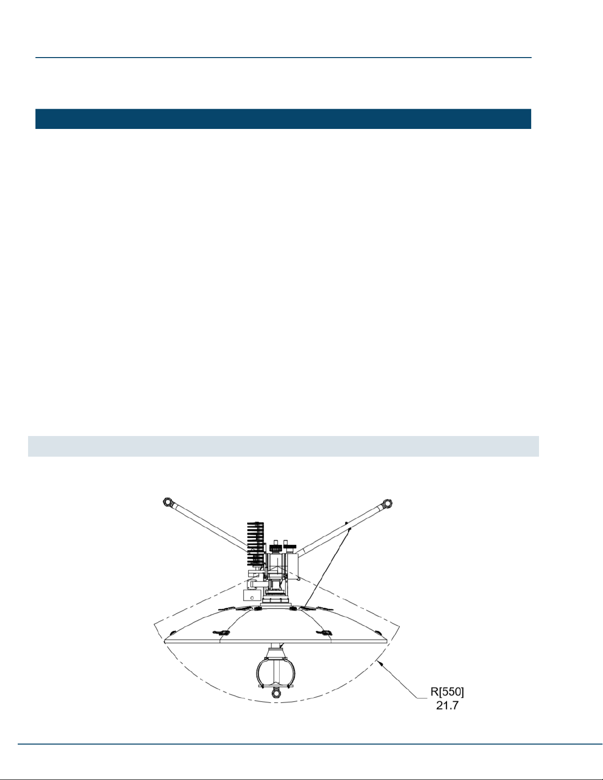
3.2. Antenna Dimensions ..................................................................................................................... 10
3.3. Introduction to System Components ............................................................................................. 12
4. Assembly............................................................................................................................................. 13
4.1. Site Selection ................................................................................................................................ 13
4.2. High Wind Setup ........................................................................................................................... 13
4.3. Antenna Assembly......................................................................................................................... 13
4.3.1. Tripod Base ................................................................................................................................ 13
4.3.2.Reector..................................................................................................................................... 15
4.3.3.Feed ............................................................................................................................................ 16
4.4. Cable Connection.......................................................................................................................... 17
5. Operation............................................................................................................................................. 18
5.1. Levelling ........................................................................................................................................ 18
5.2. Zeroing the Azimuth Dial ............................................................................................................... 19
5.3. Adjusting Antenna Position............................................................................................................ 20
5.3.1 Azimuth Adjustment..................................................................................................................... 20
5.3.2. Elevation Adjustment.................................................................................................................. 20
5.3.3. Polarization Adjustment ............................................................................................................. 21
5.4. Manual Acquisition ........................................................................................................................ 22
6. Disassembly........................................................................................................................................ 23
6.1. Preparation.................................................................................................................................... 23
6.2. Feed .............................................................................................................................................. 23
6.3.Reector........................................................................................................................................ 24
6.4. Tripod Base ................................................................................................................................... 25
7. System Troubleshooting ................................................................................................................... 27
8. System Maintenance.......................................................................................................................... 28
8.1. Maintenance Schedule.................................................................................................................. 28
8.2.ReectorClipReplacement .......................................................................................................... 28
9. Technical Specications.................................................................................................................... 30
Appendix A – Magnetic Declination Map.............................................................................................. 31

4
cDOC-000898 Rev B 07/2020
Copyright Notice
NOTICE: Norsat International Inc. (“Norsat”) assumes no responsibility for errors or omissions that may
appear in this publication. Norsat reserves the right to change this publication at any time, without notice.
Copyright © 2019. Norsat International Inc. All rights reserved.
All materials contained in this user guide are the property of Norsat International Inc. except as noted here below:
All materials in this user guide are protected by United States and international copyright laws. The
compilation of all content in this user guide is the exclusive property of Norsat.
RUGGED, ULTRA-
PORTABLE HIGH-
PERFORMANCE
SATELLITE TERMINALS
FOR COMMERCIAL
APPLICATIONS

5
© 2020 Norsat International Incorporated (“Norsat”) All Rights Reserved DOC-000898 Rev B 07/2020
REVISION DESCRIPTION Date YYYY/MM/DD
ARelease 2019/04/16
BRelease 2020/07/29
Revision History
Acronyms
AZ Azimuth
BUC Block Upconverter
CCW Counter-clockwise
CW Clockwise
EL Elevation
IFL Interfacility Link
LNB Low-noise Block Downconverter
OMT Orthomode Transducer
POL Polarization
RF Radio Frequency
SSPA Solid-SatePowerAmplier
TRF Transmit Reject Filter

6
cDOC-000898 Rev B 07/2020
Safety
Caution Grounding the Terminal
In urban areas, ground the terminal with a grounding conductor in accordance to
national and local electrical codes.
Danger FCC Radio Frequency Exposure Information for Mobile Transmitting Devices
When the power is on, maintain an off-axis safety distance of 0.7 meters (2.3 feet),
where “off axis” means 0.9 meters (3 feet) from the center of the beam, and maintain
an on-axis safety distance of 7 meters (23 feet).
Danger Electrical Hazards in Wet and Windy Conditions
While the terminal is designed for outdoor use (e.g. optional waterproof power supply),
observe the following safety precautions during windy and wet weather conditions.
SomestepsmaynotapplydependingontheBUCconguration.
1. Check cable connectors and power cords for damage or tears. Replace cables and
cords as needed.
2. Disconnect the terminal from its power source before you move it.
3. Disconnect the terminal from its power source if you suspect a power malfunction.
Warning Hot Surfaces
When transmitting, do not touch the BUC as it may result in burns or injury.

7
© 2020 Norsat International Incorporated (“Norsat”) All Rights Reserved DOC-000898 Rev B 07/2020
Danger Hazards of Microwave Radiation in Electromagnetic Fields
When the power is on, the area directly in front of the antenna is an Area of Restricted
Occupancy. Observe the following safety precautions:
1. Limit human exposure time to the area directly in front of the main antenna assembly.
2. Never place any part of your body between the antenna and the Feed Horn assembly.
3. Never place any part of your body in line with the direction of the antenna transmission path.
4. Locate the terminal as far as possible from ungrounded metal.
Dielectric Heating
Dielectric heating is the heating of an insulating material caused by placing it in a high
frequencyelectriceld.WhenahumanentersaRadioFrequency(RF)eld,thebody
actsasdielectric.IfthepowerintheRFeldexceeds10milliwattspercentimeter,the
individual will have a noticeable rise in body temperature.
The severity of burns may vary from minor to major. Burns or other damage may result
in long term injury or even death.
The vital organs of the body are highly susceptible to dielectric heating.
The eyes are also highly susceptible to dielectric heating. Do not look directly into
devices radiating RF energy.
You must not stand directly in the path of RF radiating devices
Warning Unintentional Radio Interference
This equipment generates, uses, and radiates radio frequency energy. If you install and
use the device according to the instruction manual, the device will not cause harmful
interference to radio communications.
If you operate the device in a residential area, it is likely to cause harmful interference
to radio communications; you will correct the interference at your own expense.
Warning Changes or Modications to Equipment
Changesormodicationstothisequipment,notexpresslyapprovedbythemanufacturer
could void the user’s authority to operate the equipment.
Accessories and Devices
Use of non-approved accessories or devices may lead to a degradation in performance,
damage to equipment, or potential hazards
Servicing the Equipment
Donotservicetheequipmentaloneunlessanotherpersonispresenttoadministerrst-aid

8
cDOC-000898 Rev B 07/2020
List of Contents - Case 1
NAME QUANTITY DESCRIPTION
Leg Assembly 1 Pedestal mounting base
Pedestal Assembly (ODU) 1Antenna main pedestal optionally integrated with BUC and LNB
ReectorHub 1Reectorpetalmountingbase
ReectorPetals 6Disassembledantennareector
Feed Horn 1 Horn antenna with waveguide
Mounting Pegs 3 Stake for leg assembly
IFL Cable (optional) 1 Interfacility link cable for Tx/Rx transmission
BUC M&C Cable (optional) 1 Monitor and control cable for ATOM BUC option
BUC Power Supply (optional) 1 Power supply for ATOM BUC option
ReectorPetals
ATOM BUC
Power Supply
Pedestal
ReectorHub
Leg Assembly
Mounting Pegs
IFL Cable and/or
BUC M&C Cable

9
© 2020 Norsat International Incorporated (“Norsat”) All Rights Reserved DOC-000898 Rev B 07/2020
1. Overview
The Norsat Wayfarer is an industrial strength transportable satellite communication system built strong for the most
demanding users working with the most challenging applications and environments. The Wayfarer is manually
operated,integrated,andversatileenoughfordeploymentvirtuallyanywhere,includingmobileeldofces,eld
vehicles, or directly on the ground. A complete satellite solution, the Wayfarer includes everything to meet your
communication needs.
2. System Overview
The system consists of the terminal, the BUC, the LNB, and no other electronics. The antenna is equipped with two
dials and an inclinometer to read its azimuth, polarization, and elevation position.
On the transmit side, the terminal contains a BUC and SSPA to convert the L-Band Tx signals from the modem to
Ku-BandRFsignalsandamplifythemtothespeciedpowerlevels.Theampliedsignalsarepassedthroughthe
outputwaveguidetotheOMTbeforeenteringthefeed.ThefeedprojectstheRFenergyontotheparabolicreector
up to a satellite.
Onthe receiveside, the receive RFenergy is gathered bythe reector and focused onthe feed, which directs
the energy to the OMT. The OMT is connected between two waveguide rotary joints to enable adjustment of the
polarization. The OMT then splits the receive signal and passes it to the TRF and then the LNB, which outputs
L-Band Rx signals to the modem.
Refer to the gure below for the system block diagram and the RF chain of the antenna when connected to a
modem.Thecomputerisoptionaldependingonthemodemconguration.

10
cDOC-000898 Rev B 07/2020
3. Hardware
3.1. Case Dimensions
CASE NUMBER DIMENSIONS WEIGHT
Case 1 (Pelican iM 2975) 31.30 in x 20.40 in x 15.50 in
[795 mm x 518 mm x 394 mm]
≤66lb[30kg]
3.2. Antenna Dimensions
Note: Pictures within the user manual may differ from the product.
Top view of antenna (mm):

11
© 2020 Norsat International Incorporated (“Norsat”) All Rights Reserved DOC-000898 Rev B 07/2020
Front view of antenna (in [mm]):
Side view of antenna (in [mm]):

12
cDOC-000898 Rev B 07/2020
3.3. Introduction to System Components
The Pedestal Assembly consists of three main modules: The Azimuth, Elevation, and Polarization modules. Please
refer to Section 5.3 for the operation of each module.
The azimuth module consists of the azimuth handwheel, planetary gearbox, worm gearbox, internal gear and azimuth
base. The azimuth movement is mechanically self-locking and can be manually controlled through the lower knob
on pedestal. Meanwhile, the elevation module consists of the elevation handwheel, elevation gearbox and elevation
base. The elevation movement is mechanically self-locking and can be manually controlled through the upper knob on
pedestal. Both the azimuth and elevation modules are controlled by two handwheels on the Pedestal.
The polarization module consists of the LNB and TRF attached to the OMT. Its main functionality is to isolate the
Tx and Rx signals. The polarization module can be rotated by hand to adjust the polarization and its position is
locked into place by the polarization lock knob. Installation of polarization module is optimized from factory to
ensure best performance. If the polarization module was to be removed, please mark the location of mounting
screws on the slot beforehand
Inaddition,theFeed,ReectorAssembly,andBUCmountontothePedestalAssembly.TheReectorAssemblyis
segmentedintosix(6)outerpetalsandthecentralreectorhubforcompactstorage.
The Pedestal Assembly mounts onto the Leg Assembly, which allows for leveling and angle compensation on
uneven and inclined surfaces.
Refer to the image below for the location of the system components.
ReectorPetals
Feed Horn
ReectorHub
Leg Assembly
Pedestal Assembly
LNB
BUC

13
© 2020 Norsat International Incorporated (“Norsat”) All Rights Reserved DOC-000898 Rev B 07/2020
4. Assembly
Please follow the procedure below to set up the antenna for a typical satellite acquisition.
4.1. Site Selection
Followtheguidelinesbelowtoensureoptimalperformanceoftheyawayterminal:
1. Find a clear level area. The terminal can handle up to 2.5° offset.
2. Ensure that there is line of sight towards the target satellite.
3. Ensure that you can provide a safe clearance area or prevent people from walking in the way of transmission.
4.2. High Wind Setup
Ifthesystemistobeusedinahighwindsituation,followtheguidelinesbelowtoensureyouhavesufcientballast
or equivalent tie downs to secure the base of the terminal.
WIND SPEED (km/h) 50 70 100
BALLAST (kg) 20 65 95
Note: The specied ballasts are per leg. Ballast should be located directly over footpad if possible.
4.3. Antenna Assembly
Fully read each step and any accompanying notes before performing the step.
4.3.1. Tripod Base
1. Take out the Leg Assembly from Case 1 and disengage the buckle strap
2. Unfold the Legs to the limit and re-engage up the buckle strap.
3. Disengage the Lock Handle on the Leg Assembly by rotating it upwards.
Strap Lock Handle

14
cDOC-000898 Rev B 07/2020
4. Take out the Pedestal Assembly from Case 1
5. Lift the Pedestal by the top handle and insert the Azimuth Connector into the Leg Assembly.
Note: The Pedestal Assembly can be installed in any orientation on the Leg Assembly at this step.
Lock Handle Disengaged
Azimuth Connector
Handle
6. Then lock the Pedestal into place by rotating the Lock Handle downwards. There will noticeable amount of
resistance while engaging followed by an immediate drop in resistance after engaging.
7. Refer to Section 5.2 to zero the azimuth dial.

15
© 2020 Norsat International Incorporated (“Norsat”) All Rights Reserved DOC-000898 Rev B 07/2020
4.3.2.Reector
1. Set the EL angle to 10 degrees for ease of assembly. Refer to Section 5.3.2. for elevation adjustment.
2.TakeouttheCenterReectorHubfromCase1.
3.InstalltheCenterReectorHubbyaligningthematingcentralHubpetalsonthePedestalAssemblyandthen
lock the Hub into place by rotating it clockwise.
4. Take out the Petals from Case 1.
Note: Each petal is labeled with a matching number to indicated where it is installed on the Reector Hub.
5.FirstinstallPetal1byrstinsertingthelocatingstubsonthepetalintotheReectorHub.Thenengagethehub-
side latches.
Note: Exercise caution when installing the rst two petals because petals are not self-supporting until 1 set
of petal-side latches have been engaged.
Petal-Side Latch
Hub-Side Latch

16
cDOC-000898 Rev B 07/2020
6. Install the remaining petals in increasing order by performing the steps below:
a. Adjust the elevation angle as needed to access the hub-side latches.
b.InsertthelocatingstubonthepetalintothematingslotintheReectorHubandanyadjacentpetals.
c. Engage all petal-side latches.
d. Engage all hub-side latches.
Note: If the polarization assembly is blocking the hub-side latches, refer to Section 5.3.3 to adjust the
position of the polarization assembly.
4.3.3.Feed
1. Take out the Feed Horn from Case 1
2. Install onto the Pedestal by rotating the Feed Collar along the threads on the Pedestal
Note: Feed Horn can be installed onto the Pedestal in any orientation.
Feed Collar

17
© 2020 Norsat International Incorporated (“Norsat”) All Rights Reserved DOC-000898 Rev B 07/2020
3. Antenna assembly is now complete.
4.4. Cable Connection
1. Connect the cables according to the table and diagram below:
Warning: Connect the Modem Tx Coax Cable last and ensure user is clear of the antenna to avoid accidental
transmission.

18
cDOC-000898 Rev B 07/2020
5. Operation
5.1. Levelling
1. Loosen the locking nut on the foot to be adjusted
Foot Adjustment Knob
Locking Nut
2. Examine the location of the bubble in the Bubble Level on the Pedestal.
3. Decrease the height of the footpad(s) closest to the bubble and/or increase the height of the footpad(s) farthest
to center the bubble. Turn the foot adjustment screw CW or CCW to elevate or lower the foot respectively.
Bubble Level
4. Continue adjusting the footpad heights until the bubble in the Bubble Level is centered.
5. Once the system is leveled, ensure the locking nuts are tightened on all feet.

19
© 2020 Norsat International Incorporated (“Norsat”) All Rights Reserved DOC-000898 Rev B 07/2020
5.2. Zeroing the Azimuth Dial
1. Set the Azimuth to 360 degrees if the terminal is set in the northern hemisphere. Otherwise, set the Azimuth to
180 degrees for use in the southern hemisphere. Refer to Section 5.3 for azimuth adjustment information.
2. Unlock the Lock Handle of the Leg Assembly and rotate the Pedestal Assembly until the Pedestal’s engraved
arrow points towards the equator.
3. Re-engage the Lock Handle of the Leg Assembly.
Engraved Arrow

20
cDOC-000898 Rev B 07/2020
5.3. Adjusting Antenna Position
5.3.1 Azimuth Adjustment
1. Use the lower handwheel to control the azimuth position of the terminal.
a. Rotate the handwheel CW to move the azimuth to the left
b. Rotate the handwheel CCW to move the azimuth to the right
2. Use the azimuth scale on the bottom of the pedestal to read the current azimuth position
5.3.2. Elevation Adjustment
1. Use the upper handwheel to control the elevation position of the terminal.
• Rotate the handwheel CW to move the elevation to the down
• Rotate the handwheel CCW to move the elevation to the up
2. Use the inclinometer on the side of the pedestal to read the current elevation position
Elevation Handwheel
Inclinometer
Azimuth Handwheel
Azimuth Dial
Table of contents
Other Norsat Antenna manuals

Norsat
Norsat Wayfarer User manual

Norsat
Norsat Wayfarer User manual

Norsat
Norsat WAYFARER 1.0M KU-BAND User manual

Norsat
Norsat Wayfarer User manual

Norsat
Norsat WFM180KU User manual

Norsat
Norsat Wayfarer User manual

Norsat
Norsat WAYFARER KU-BAND WFA120KU-EU User manual

Norsat
Norsat WAYFARER 1.2M KA-BAND User manual

Norsat
Norsat GLOBETrekker User manual

Norsat
Norsat Sinclair StealthWave SHA211 User manual