Norsat Element C-Band BUC User manual

Operator Manual for Element
C-Band 10W BUC

©Norsat International Inc. (“Norsat”) All Rights Reserved
2022-06-01 DOC-001803 Rev A 2
TABLE OF CONTENTS
1.1 Overview.................................................................................................................. 5
Introduction of BUC........................................................................................... 5
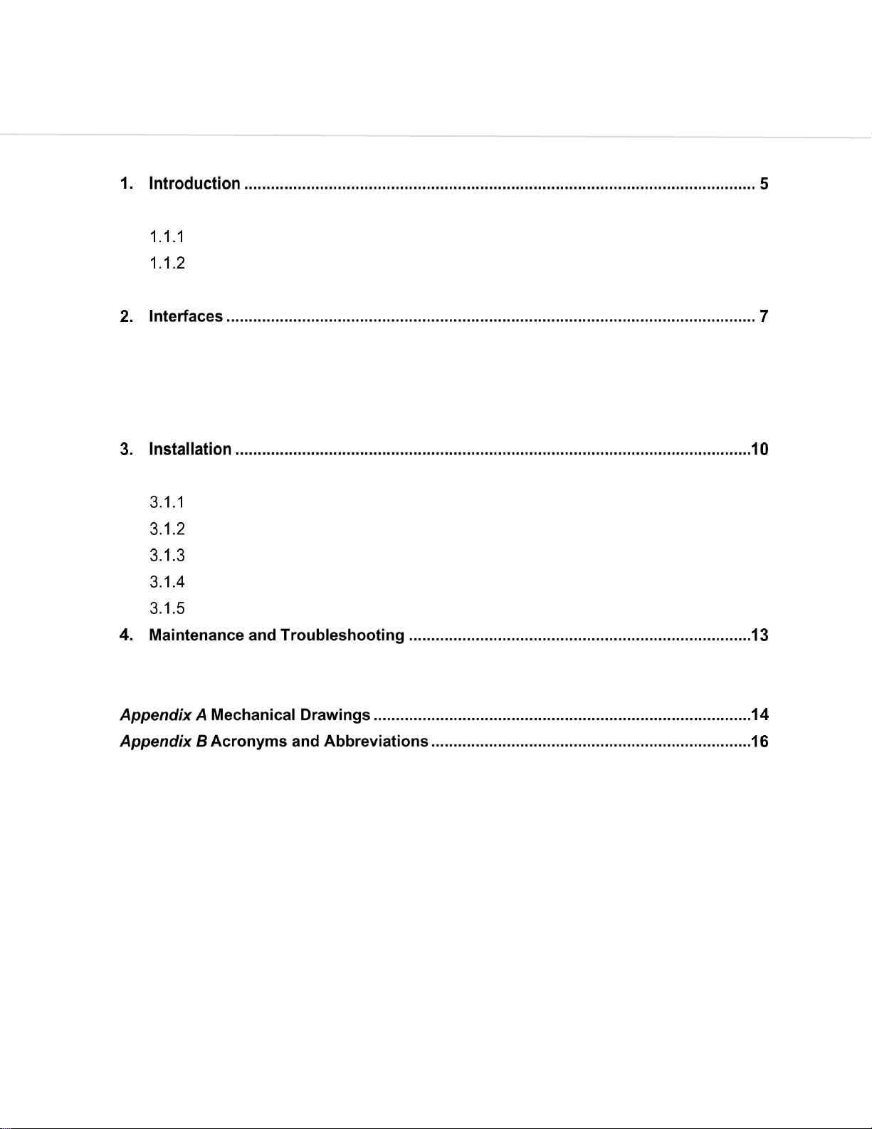
Physical Description.......................................................................................... 5
1.2 Safety....................................................................................................................... 6
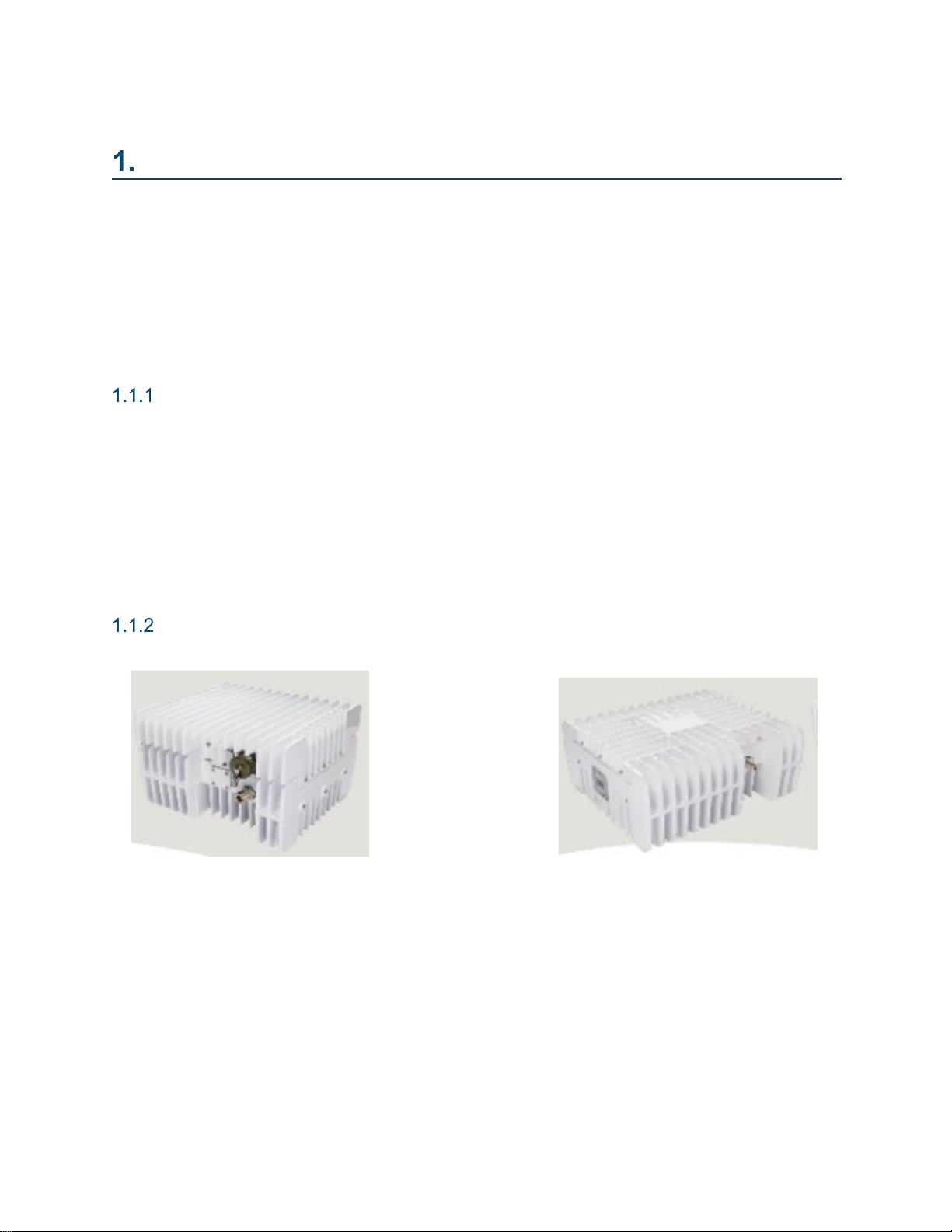
2.1 Intermediate Frequency (IF)/ 10MHz Reference Input.............................................. 7
2.2 Torque Value............................................................................................................ 8
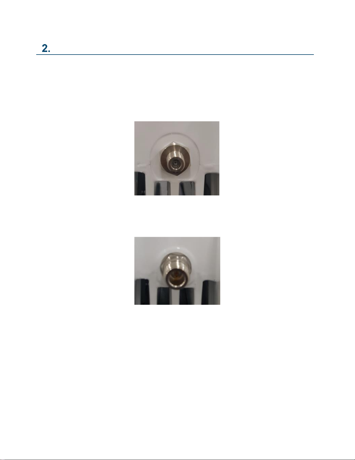
2.3 RF Output................................................................................................................. 8
2.4 AC/DC Connector..................................................................................................... 8
3.1 Element BUC Installation.........................................................................................10
Check packing list ............................................................................................10
Installation of mounting bracket........................................................................10
Connecting coaxial cable and DC.....................................................................11
Installation of OMT to CPR137G......................................................................11
Waterproof .......................................................................................................11
4.1 Maintenance............................................................................................................13
4.2 Troubleshooting.......................................................................................................13

©Norsat International Inc. (“Norsat”) All Rights Reserved
2022-06-01 DOC-001803 Rev A 3
LIST OF FIGURES
Figure 2-1: F-Type female connector.............................................................................................................................7
Figure 2-2: N-Type female connector.............................................................................................................................7
Figure 2-3: CPR137G RF Output Port ...........................................................................................................................8
Figure 2-4: MS 5pin for AC ............................................................................................................................................9
Figure 2-5: MS 2pin for DC ............................................................................................................................................9
Figure 3-1: Location of mounting bracket holes ...........................................................................................................10
Figure A-4- 1: Element 10W BUC (DC Power).............................................................................................................14
Figure A-4- 2: Element 10W BUC (AC Power).............................................................................................................15

©Norsat International Inc. (“Norsat”) All Rights Reserved
2022-06-01 DOC-001803 Rev A 4
LIST OF TABLES
Table 2-1: Torque Value ................................................................................................................................................8
Table 3-1: Torque Value ..............................................................................................................................................11
Table 3-4: Torque Value ..............................................................................................................................................11
Table B-4- 1: Acronyms and Abbreviations..................................................................................................................16

©Norsat International Inc. (“Norsat”) All Rights Reserved
2022-06-01 DOC-001803 Rev A 5
Introduction
1.1 Overview
The purpose of this document is to provide instruction for installation, operation, and maintenance of the
10W C-band Block Upconverter (BUC).
We recommend that the users familiarize themselves with the product by reading through this manual
before installation to reduce the possibility of incorrect installation and operation.
Introduction of BUC
The BUC is designed to use for VSAT application. Norsat BUC has high linearity and gain stability over the
full operating temperature range. The standard output operating frequency range is 5.850GHz to 6.425GHz.
Other frequency options are also available ranging from 5.850GHz to 7.025GHz. The BUC requires a
reference signal (10MHz) either externally or internally to maintain the correct transmit frequency. The BUC
has either a F-type or N-type female connector for input and CPR137G waveguide with a grooved flange
for output.
Physical Description
AC Picture DC Picture

©Norsat International Inc. (“Norsat”) All Rights Reserved
2022-06-01 DOC-001803 Rev A 6
1.2 Safety
The BUC should be handled with care to avoid potential safety risks. Read the following instructions prior
to using the BUC. Norsat is not responsible for damages occurred by unsafe handling of the product.
1. Do not disassemble the BUC. It may cause malfunction and electrical shock.
2. Input a voltage within the range indicated in the specification.
3. Do not operate the BUC without a load or termination attached to the RF signal output.
4. Do not expose the BUC to standing water. Failure to follow this precaution could result in electric
shock and injury to persons.
5. The BUC should be installed in an electrically stable situation because it may cause serious
injuries to persons as well as damage to the BUC.
6. Do not perform maintenance to the BUC when the power supply is connected.
7. Do not look into the waveguide opening when the BUC is powered on.
8. Do not touch the body during operation of the BUC.
9. Do not operate the BUC out of the operating temperature range, -40C to +55C.

©Norsat International Inc. (“Norsat”) All Rights Reserved
2022-06-01 DOC-001803 Rev A 7
Interfaces
2.1 Intermediate Frequency (IF)/ 10MHz Reference Input
Intermediate Frequency (IF) and 10MHz reference signal are provided through F or N type connector. F or
N type connector is used for the input port as shown in Figure 2-1 and Figure 2-2.
Figure 2-1: F-Type female connector
Figure 2-2: N-Type female connector

CONFIDENTIAL AND PROPRIETARY
©Norsat International Incorporated (“Norsat”) All Rights Reserved
2022-06-01 DOC-001803 Rev A 8
2.2 Torque Value
The torque value to connect the coaxial cable is shown in Table 2-1.
Table 2-1: Torque Value
Connector
Torque value (N/m)
F-type
0.39 - 0.49
N-type
0.68 - 1.13
*1 [kg f/cm] = 0.0980 [N/m]
2.3 RF Output
CPR137G waveguide (Grooved) is used for the RF output port as shown in Figure 2-3.
2.4 AC/DC Connector
MS 5pin connector is used for AC and MS 2pin connector is used for DC as shown in Figure 2-4 and Figure
2-5.
Figure 2-3: CPR137G RF Output Port

CONFIDENTIAL AND PROPRIETARY
©Norsat International Incorporated (“Norsat”) All Rights Reserved
2022-06-01 DOC-001803 Rev A 9
Figure 2-4: MS 5pin for AC
Figure 2-5: MS 2pin for DC

CONFIDENTIAL AND PROPRIETARY
©Norsat International Incorporated (“Norsat”) All Rights Reserved
2022-06-01 DOC-001803 Rev A 10
Installation
3.1 Element BUC Installation
The BUC must be attached to some form of a mounting structure which is usually the antenna feed horn or
the antenna support structure. Specific mounting procedures will depend on the antenna used. The BUC is
designed to be easily mounted on most of antenna produced by manufacturer. Locate and install the
antenna according to the antenna manufacturer’s instructions. Choose an area that is free of interference
from motors and electronic equipment.
Check packing list
Perform an initial inspection upon receiving the BUC as per the following instruction:
•Check that the shipping container is not damaged.
•Check that all items in the packing list are not damaged.
•Check that all items in the packing list are present.
Installation of mounting bracket
Install the mounting bracket using the two (2) M6 mounting holes at each side of BUC as shown in Figure
3-1. The BUC requires a steady flow of air. To provide sufficient airflow, the BUC shall be properly oriented
with the deepest heat sink fins facing up. The BUC has body and cover heat sinks with numerous radiator
fins for cooling. Please do not block the fins so that heat sinks are open to fresh air. Adequate cooling for
the BUC is important in providing years of top performance.
Figure 3-1: Location of mounting bracket holes

CONFIDENTIAL AND PROPRIETARY
©Norsat International Incorporated (“Norsat”) All Rights Reserved
2022-06-01 DOC-001803 Rev A 11
The torque value to install mounting bracket is shown in Table 3-1.
Table 3-1: Torque Value
Bolt
Torque value (N/m)
M6X10MM
12
*1 [kg f/cm] = 0.0980 [N/m]
Connecting coaxial cable and DC
The length (and associated RF losses) of the interconnecting cables must be considered when determining
the installing location of the BUC. An inappropriate choice of cable may result in a reduction of output power
or even no voltage applied to the BUC. Connect the cable at each side tightly. Make sure that the external
connectors are waterproof.
Installation of OMT to CPR137G
BUC can be mounted with waveguide filter or OMT of antenna. Do not block fins and air opening of the fan.
Please follow the guidelines below.
1. Clean the gasket groove on the waveguide flange.
2. Insert the enclosed gasket to the groove.
3. Use the enclosed bolts and washers (8pcs) to install OMT.
4. The torque value to install OMT is shown in Table 3-2.
Table 3-2: Torque Value
Bolt
Torque value (N/m)
#10-32UNF
7
*1 [kg f/cm] = 0.0980 [N/m]
Waterproof
The application of self-amalgamating tape is strongly recommended. Ensure the waveguide joints are
properly sealed with the gasket supplied. Use the self-amalgamating tape provided to seal the junction
between the connector and coaxial cable. Detail instruction to use the self-amalgamating tape is as
following:
1. Connect the coaxial cable to BUC connector.

CONFIDENTIAL AND PROPRIETARY
©Norsat International Incorporated (“Norsat”) All Rights Reserved
2022-06-01 DOC-001803 Rev A 12
2. Tighten connector and coaxial cable all the way to the end.
3. Tightly wrap the connector and coaxial cable with the self-amalgamating tape.
4. Tightly wrap the waveguide filter or OMT with the self-amalgamating tape.

CONFIDENTIAL AND PROPRIETARY
©Norsat International Incorporated (“Norsat”) All Rights Reserved
2022-06-01 DOC-001803 Rev A 13
Maintenance and Troubleshooting
4.1 Maintenance
Norsat BUC is reliable, requiring little maintenance or repair. This contains technical information to help
diagnose basic failures.
Maintenance is limited to check the performance of the BUC. No electrical or mechanical adjustment is
required for normal operation. Periodic cleaning of the heat sink fins will ensure adequate ambient cooling.
Not to cover the fan, which may increase the heat sink temperature.
4.2 Troubleshooting
The recommended action below provides some help to quickly isolate a fault within the BUC module. If the
BUC module is defective, notify Norsat of a written description of the problem encountered, the part number
and serial number of the unit in question.
Symptom: Fails performance test
1. Check power source
2. RF source
3. 10MHz source
4. Cabling and connectors
5. Check debris in the fan and heat sink fins (clean thoroughly)

CONFIDENTIAL AND PROPRIETARY
©Norsat International Incorporated (“Norsat”) All Rights Reserved
2022-06-01 DOC-001803 Rev A 14
Appendix A Mechanical Drawings
Figure A-4- 1: Element 10W BUC (DC Power)

CONFIDENTIAL AND PROPRIETARY
©Norsat International Incorporated (“Norsat”) All Rights Reserved
2022-06-01 DOC-001803 Rev A 15
Figure A-4- 2: Element 10W BUC (AC Power)

CONFIDENTIAL AND PROPRIETARY
©Norsat International Incorporated (“Norsat”) All Rights Reserved
2022-06-01 DOC-001803 Rev A 16
Appendix B Acronyms and Abbreviations
The following is a list of acronyms and abbreviations referenced in this document.
Table B-4- 1: Acronyms and Abbreviations
Acronym
Definition
BUC
Block Upconverter
IF
Intermediate Frequency
DC
Direct Current
GHz
Gigahertz
GND
Ground
M&C
Monitor and Control
MHz
Megahertz
mm
Millimeter
RF
Radio Frequency
RX
Receive
TX
Transmit
V
Volt
VDC
Volts Direct Current

CONFIDENTIAL AND PROPRIETARY
©Norsat International Incorporated (“Norsat”) All Rights Reserved
2022-06-01 DOC-001803 Rev A 17
ABOUT NORSAT
Norsat International Inc., founded in
1977, is a leading provider of innovative
communication solutions that enable the
transmission of data, audio and video
for remote and challenging applications.
Norsat’s products and services include
customizable satellite components,
portable satellite terminals, maritime
solutions and satellite networks. The
company’s products and services are
used extensively by
telecommunications services providers,
emergency services and homeland
security agencies, military
organizations, health care providers and
Fortune 1000 companies.
110 –4020 Viking Way | Richmond | British Columbia | Canada
V6V 2L4 | support@norsat.com
www.norsat.com
Table of contents
Other Norsat Industrial Equipment manuals
Popular Industrial Equipment manuals by other brands

Wilo
Wilo Wilo-Flumen OPTI-TR 28-1 Installation and operating instructions

Nidec
Nidec Leroy-Somer TAL 047 Installation and Maintenance

Durlum
Durlum LOOP TYPE 3 installation manual

Lennox
Lennox EL195UHNE Series manual

Nexen
Nexen Air Champ B275 user manual

ATI Technologies
ATI Technologies 39-0214 quick start guide

Festo
Festo MPS 8049013 Getting started

SMC Networks
SMC Networks AS Series manual

Precision Rated Optics
Precision Rated Optics OFS-943V Operation guide

Regulus
Regulus PS 400 K+ Installation and operation manual

SCHUNK
SCHUNK EGS Series Assembly and operating manual

Baby Lock
Baby Lock EMP6 Technical training