Norsat ATOM Ku GaN Series User manual

ATOM Ku GaN 20-40-80W BUC &
SSPA
052910
1
052910_rA - Operator Manual for ATOM Ku
GaN Series 20-40-80W
ATOM Ku GaN 20-
40-80W BUC &
SSPA
Operator’s Manual
Document Number: 052910
Revision A
Norsat International Inc.
110 –4020 Viking Way
Richmond, British Columbia
Canada V6V 2L4

ATOM Ku GaN 20-40-80W BUC &
SSPA
052910
2
052910_rA - Operator Manual for ATOM Ku
GaN Series 20-40-80W
ATOM Ku GaN 20-40-80W BUC & SSPA
OPERATOR’S MANUAL
The information in this document has been fully reviewed and is believed to be entirely reliable. However,
Norsat International Inc., hereinafter referred to as Norsat, reserves the right to modify any products to
improve reliability, function, or design. Norsat does not assume any liability arising out of the application
or use of any product or circuit described herein. Norsat does not convey any license under its patent
rights or the rights of others.
TECHNICAL SUPPORT
This manual provides engineers with information necessary to operate the applicable system. Technical
support is available from Norsat.
Norsat International Inc.
Attn: Technical Support
110 –4020 Viking Way
Richmond, BC
Main: 1 (604) 821-2800
Support: 1 800 644 4562

ATOM Ku GaN 20-40-80W BUC &
SSPA
052910
3
052910_rA - Operator Manual for ATOM Ku
GaN Series 20-40-80W
REVISION HISTORY
Rev
CO #
Reason for Change
Reviewed
By
Author
Date
mm/dd/yyyy
A
CN-1023
Initial Release
SL
FY, TK
03/20/2020
Non-Digital Approval (Only if required)
Scan this page with signature and attach to Change Order if this section used
Approver Name:
Approver Signature:
Date:

ATOM Ku GaN 20-40-80W BUC &
SSPA
052910
4
052910_rA - Operator Manual for ATOM Ku
GaN Series 20-40-80W
TABLE OF CONTENTS
Operator’s Manual................................................................................................................................................2
Technical Support................................................................................................................................................2
Revision History...................................................................................................................................................3
Table of Contents.................................................................................................................................................4
List of Figures.......................................................................................................................................................5
List of Tables........................................................................................................................................................5
CHAPTER 1 INTRODUCTION.....................................................................................................................6
SECTION 1.1 OVERVIEW.............................................................................................................................6
SSPA –Solid State Power Amplifier....................................................................................................................6
BUC - Block Up Converter and Amplifier .............................................................................................................6
SECTION 1.2 FEATURES .............................................................................................................................7
Inputs and Outputs...............................................................................................................................................7
Electrical Interface................................................................................................................................................7
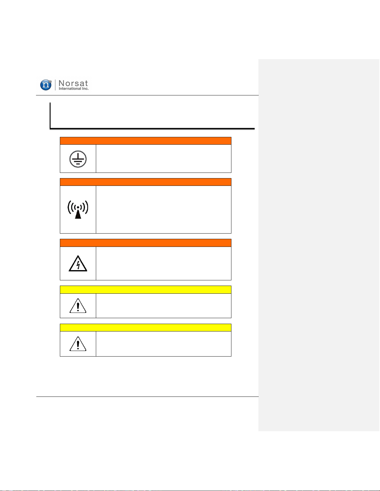
SECTION 1.3 SAFETY .................................................................................................................................8
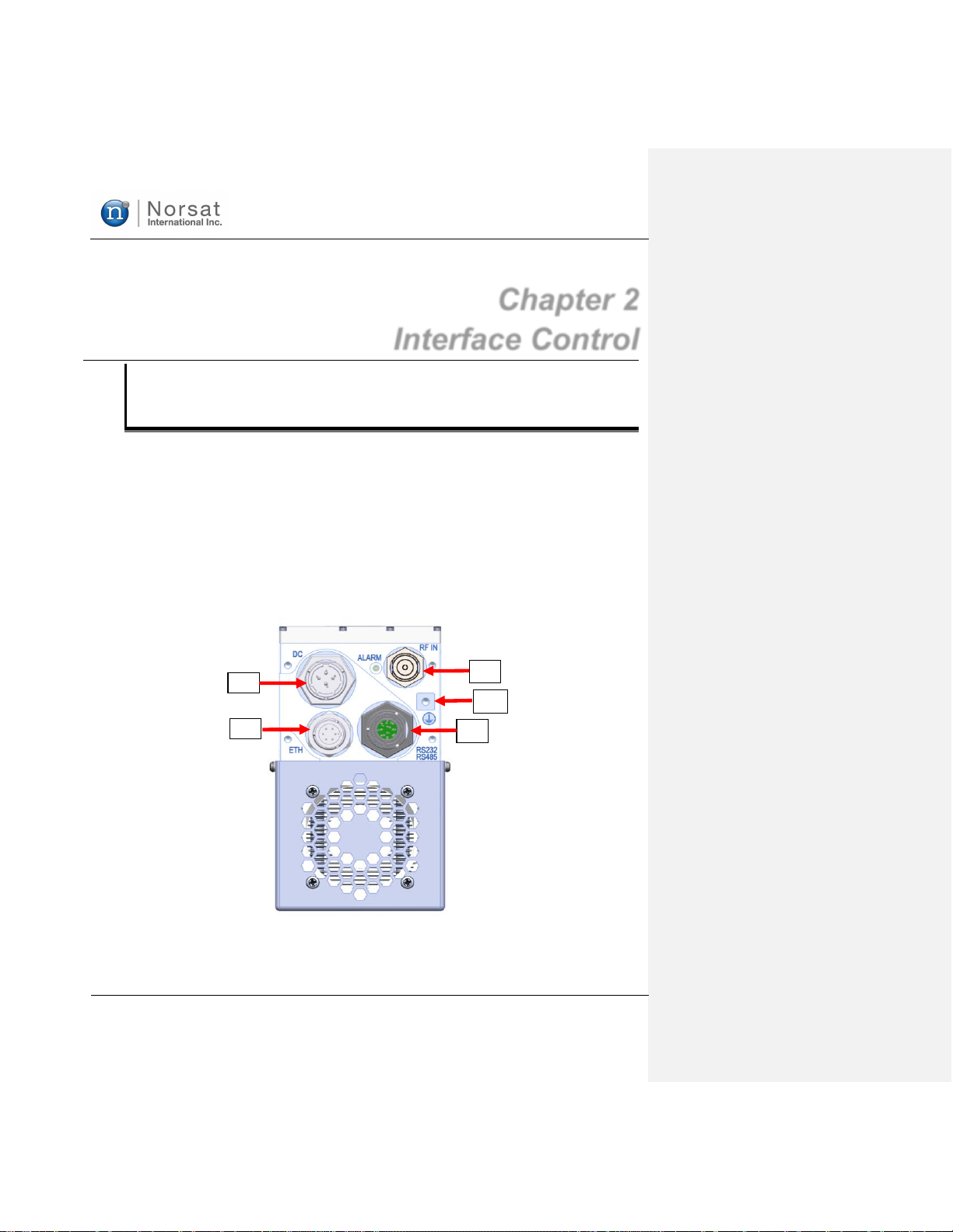
CHAPTER 2 INTERFACE CONTROL .........................................................................................................9
SECTION 2.1 INTRODUCTION.......................................................................................................................9
SECTION 2.2 J1 –IF/RF INPUTS...............................................................................................................11
J1 –IF/RF Input .................................................................................................................................................11
SECTION 2.3 J2 –MONITOR AND CONTROL INTERFACE..............................................................................12
Monitor and Control Interface Pinout..................................................................................................................12
SECTION 2.4 J3 –ETHERNET PORT ..........................................................................................................14
ETHERNET PORT PINOUT ............................................................................................................................14
SECTION 2.5 PERFORMING FIRMWARE UPDATE..........................................................................................15
SECTION 2.6 J4 –DC POWER ..................................................................................................................19
SECTION 2.7 SERIAL PORT SOFTWARE INTERFACE....................................................................................20
Controller Responses.........................................................................................................................................20
Message Definitions...........................................................................................................................................20
Command Response .........................................................................................................................................22
Mute Logic .........................................................................................................................................................23
SECTION 2.8 ETHERNET INTERFACE (ATOMCONTROL™WEB INTERFACE &ATOM SNMP AGENT)...........25
Default IP Address.............................................................................................................................................25
Changing the ATOM-Series Device’s IP Address ..............................................................................................25
Recovering the ATOM-Series Device’s IP Address ...........................................................................................26
Accessing ATOMControl™ Web Interface .........................................................................................................26
Using ATOMControl™ Web Interface ................................................................................................................27
Accessing ATOM SNMP Agent..........................................................................................................................27
Configuring ATOM SNMP Agent........................................................................................................................27
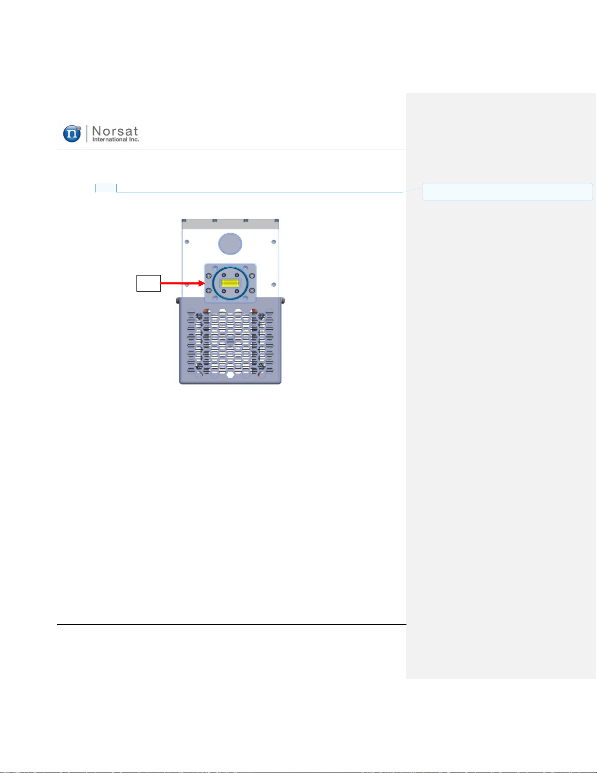
SECTION 2.9 J5 –RF OUTPUT ..................................................................................................................31
SECTION 2.10 GROUND CONNECTION.......................................................................................................31
SECTION 2.11 FAULT INDICATOR /LED.....................................................................................................32
Description of Operation ...................................................................................................................................32
Modes of Operation...........................................................................................................................................32
Starting with No Faults Status...........................................................................................................................32
Fault and No Faults............................................................................................................................................32
CHAPTER 3 MISC. INFO ...........................................................................................................................33
SECTION 3.1 ATOM INSTALLATION...........................................................................................................33
Mounting............................................................................................................................................................33
Outdoor Use.......................................................................................................................................................33
SECTION 3.2 FANS &BASEPLATE COOLING...............................................................................................33
SECTION 3.3 ACCESSORIES......................................................................................................................34
SECTION 3.4 GENERAL SPECIFICATIONS ...................................................................................................34

ATOM Ku GaN 20-40-80W BUC &
SSPA
052910
5
052910_rA - Operator Manual for ATOM Ku
GaN Series 20-40-80W
SECTION 3.5 STANDARD WARRANTY.........................................................................................................35
APPENDIX A MECHANICAL DRAWINGS ........................................................................................36
APPENDIX B ACRONYMS AND ABBREVIATIONS.........................................................................38
LIST OF FIGURES
Figure 2-1 Input Connections for ATOM Ku GaN BUC Unit (N-Type Jack Shown)..........................................................
Figure 2-2 Standard Waveguide WR75 Output for ATOM Ku GaN Unit..........................................................................
Figure 2-3: J2 M&C Connector Pin Arrangement........................................................................................................12
Figure 2-4 J3 Ethernet Connector Pin Arrangement....................................................................................................14
Figure 2-5: Firmware Version from ATOMControl FW Update Tab..............................................................................15
Figure 2-6: FW Image Browse Function.......................................................................................................................16
Figure 2-7: Image File Selection Dialog.......................................................................................................................16
Figure 2-8: Image File Confirmation and Start Update Function..................................................................................17
Figure 2-9: Progress Bar Indicates Firmware Update Progress...................................................................................17
Figure 2-10: Confirmation of Updated Firmware Version.............................................................................................18
Figure 2-11: DC Unit J4 Connector Pinout...................................................................................................................19
Figure 2-12: Setup Serial Port......................................................................................................................................20
Figure 2-13: Command getident (Ref Only) ................................................................................................................20
Figure 2-14: Command getstatus................................................................................................................................21
Figure 2-15: Command getfaults.................................................................................................................................21
Figure 2-16: Command setmute - mute unit................................................................................................................22
Figure 2-17: Command setmute - unmute unit............................................................................................................22
Figure 2-18: The Mute Logic Diagram..........................................................................................................................24
Figure A-3-1: 20-40-80W Ku GaN BUC/SSPA, Fan Cooled........................................................................................36
Figure A-3-2: 20-40-80W Ku GaN BUC/SSPA, Baseplate Cooled...............................................................................37
LIST OF TABLES
Table 1-1: Input and Outputs ........................................................................................................................................7
Table 2-1: J2 Pinouts for ATOM Configurations...........................................................................................................12
Table 2-2: ATOM Mute Control Behavior.....................................................................................................................13
Table 2-3 J3 Pinouts for Ethernet Port.........................................................................................................................14
Table 2-4: DC Unit J4 Connector Pinout.....................................................................................................................19
Table 2-5: Command Summary..................................................................................................................................23
Table 3-1: General 20-40-80W ATOM Ku GaN Specifications ....................................................................................34
Table B-3-2: Acronyms and Abbreviations...................................................................................................................38

ATOM Ku GaN 20-40-80W BUC &
SSPA
052910
6
052910_rA - Operator Manual for ATOM Ku
GaN Series 20-40-80W
Chapter 1
Introduction
Section 1.1
OVERVIEW
This operator’s manual applies to all ATOM SSPAs and BUCs with the following marketing numbers:
ATOMBKUGxxx (020/040/080W)
ATOMSKUGxxx (020/040/080W)
SSPA –SOLID STATE POWER AMPLIFIER
If this unit is a SSPA, the RF input signal is amplified to the specified power.
BUC -BLOCK UP CONVERTER AND AMPLIFIER
If this unit is a BUC, the IF input signal is upconverted to Ku-Band RF frequencies and then amplified to
the specified power.

ATOM Ku GaN 20-40-80W BUC &
SSPA
052910
7
052910_rA - Operator Manual for ATOM Ku
GaN Series 20-40-80W
Section 1.2
FEATURES
INPUTS AND OUTPUTS
Table 1-1: Input and Outputs
20W / 40W / 80W
Input Type
Female N-Type Connector (BUC)
Output Type
Waveguide WR75 (Standard)
Waveguide WR62 (Wide Band Option)
Adaptors are available to convert output type to SMA, TNC, or N-Type connectors. Please
contact Norsat for more information.)
ELECTRICAL INTERFACE
•M&C Connector –a ten-pin connector is used to interface with a host computer. See Section 2.3
J2 –Monitor and Control Interface for detailed description of the pinouts.
•Ethernet Connector –a six-pin connector is used to update the firmware and communicate with
the BUC/SSPA through the web-based ATOMControl interface. See Section 2.4 J3 –Ethernet
port for detailed description of pinouts.
•Power Connector –DC Units use a four-pin connector to provide power to the ATOM. See
Section 2.5 J4 –DC Power for detailed description of pinouts.
•Ground Terminal –a #10-32 screw is used to ground the chassis during use.

ATOM Ku GaN 20-40-80W BUC &
SSPA
052910
8
052910_rA - Operator Manual for ATOM Ku
GaN Series 20-40-80W
Section 1.3
SAFETY
W A R N I N G
Leakage Current
The ATOM may exhibit high leakage current during use.
Ensure that the ground terminal is grounded according to local
electrical codes prior to powering on the ATOM.
W A R N I N G
RF Radiation Hazard
The ATOM emits high power RF energy which is harmful to
the human body. Do not operate ATOM unless the RF output
flange is either terminated in an RF load (100W min) or
connected to the feed of a terminal.
Do not obstruct the RF output or feed output with any body
part.
W A R N I N G
Do not allow equipment to be standing in water.
While the BUC/SSPA is designed to be used outdoors, the
equipment is not designed to operate in standing water.
Failure to follow this precaution could result in electric shock
and injury to persons.
C A U T I O N
Do not allow any items to fall into the unit from the waveguide
opening.
C A U T I O N
Apply voltage to the AC/DC input connector only as specified
in the original configuration of this unit. Application of a voltage
outside the specified range may cause the unit to become
damaged or non-functional.

ATOM Ku GaN 20-40-80W BUC &
SSPA
052910
9
052910_rA - Operator Manual for ATOM Ku
GaN Series 20-40-80W
Chapter 2
Interface Control
Section 2.1
INTRODUCTION
The unit has four connectors on the input side of the housing and one waveguide port on the output side.
The interface for these connectors is detailed in this document.
On the input side, there are the following connectors:
•J1 –IF or RF Input; N-Type Jack
•J2 –Ten-pin circular shell size 12 Amphenol connector for M&C (RS232/RS485)
•J3 –Six-pin circular shell size 10 Amphenol connector for Ethernet
•J4 –Four-pin circular shell size 12 Amphenol DC power connector
•J6 –Ground terminal
Figure 2-1 Input Connections for ATOM Ku GaN BUC Unit
(N-Type Jack Shown)
J2
J1
J3
J4
J6

ATOM Ku GaN 20-40-80W BUC &
SSPA
052910
10
052910_rA - Operator Manual for ATOM Ku
GaN Series 20-40-80W
On the output side, there is one connector:
•J5 –WR75 waveguide RF output
•J5 Option: WR62 waveguide RF output for wide band
J5
Figure 2-2 Standard Waveguide WR75 Output for ATOM Ku GaN Unit
Commented [WP1]: Please add wide band WR62 flange
output

ATOM Ku GaN 20-40-80W BUC &
SSPA
052910
11
052910_rA - Operator Manual for ATOM Ku
GaN Series 20-40-80W
Section 2.2
J1 –IF/RF INPUTS
J1 –IF/RF INPUT
BUC
The IF input is a 50 ohm type-N connector. The input is to be applied here (950-1700 MHz for Extended
Band; 950-1450 MHz for Standard Band). Also, the 10 MHz signal input is diplexed onto this line.
Therefore, the IF signal and 10 MHz reference are both traveling on this line. The connector is DC-
blocked. Do not exceed +/- 50VDC on this port.
The 10-MHz signal should be accurate within +/- 1ppm, otherwise the BUC may have difficulty phase
locking to it. The 10-MHz should be free of sideband spurs, particularly close-in (under 100 kHz), as these
may also cause failure to lock. Power level of the 10 MHz reference signal should be +/-5 dBm.
SSPA
In the SSPA-only configuration, this is the RF input. It is a precision type-N connector, with performance
to 18GHz. No 10 MHz reference is required for SSPA-only operation.

ATOM Ku GaN 20-40-80W BUC &
SSPA
052910
12
052910_rA - Operator Manual for ATOM Ku
GaN Series 20-40-80W
Section 2.3
J2 –MONITOR AND CONTROL INTERFACE
The M&C interface is used to control the unit with a host computer. All on-board sensors are accessed
through this interface. Use of this connection is optional. Each ATOM is supplied with a mating
connector for the M&C interface.
MONITOR AND CONTROL INTERFACE PINOUT
The M&C interface is a ten-pin miniature circular connector. This connector is a MIL-C-26482 Series 1
receptacle, shell size 12, 10 pin (Amphenol® part number 93-533723-10P). A mating connector is
Amphenol® part number PT06E-12-10S-476. A range of compatible part numbers for the mating
connector may be used to add options to the plug such as right-angle, stress relief clamp, metal
color/finish, etc. Please contact the connector manufacturer for more information and/or refer to
Amphenol® catalog 12-070.
Figure 2-3: J2 M&C Connector Pin Arrangement
Table 2-1 summarizes the various pinout for the 20-40-80W ATOM Ku GaN.
Table 2-1: J2 Pinouts for ATOM Configurations
Connector
Pin
Standard
Configuration
Connector
Pin
Standard
Configuration
A
RS-485 Rx-
F
RS-232 Rx
B
RS-485 Rx+
G
GND
C
RS-485 Tx+
H
Open
D
Mute
J
RS-485 Tx-
E
RS-232 Tx
K
Open
Ground Pin(s): Pin G
Ground/shield for Ethernet, RS-485, RS-232 & Mute signals. This is internally connected to the case
ground. Do not exceed 100mA.

ATOM Ku GaN 20-40-80W BUC &
SSPA
052910
13
052910_rA - Operator Manual for ATOM Ku
GaN Series 20-40-80W
Mute Control: Pin D
This pin controls the hardware mute state of the ATOM. When muted, the power transistors are turned
off, reducing power consumption and providing an RF output noise close to the thermal noise floor.
The operation of this pin is fully configurable through the M&C Interface. Pin D can be biased with either
an internal Pull-Down (to 0V) or an internal Pull-Up (to 4V). Pin D is also configurable to be either active
high (3-5V on Pin D will mute the unit) or active low (0-0.8V on Pin D will mute the unit). All voltages are
relative to Pin G or the Case Ground.
Because of the configurable pull-down / pull-up resistor, the unit can be configured to be active (i.e. not
muted) when Pin D is left floating. Therefore, it is possible to operate the unit with no connection pin D.
The ATOM mute control behavior is shown below in Table 2-2. Note that the ATOM may be factory
ordered with alternate configurations, so the Default configuration shown in the table is not reflective of all
ATOM units.
Table 2-2: ATOM Mute Control Behavior
Configuration
Mute Line
Polarity
Mute Line
Bias
Sample
Input 1
Sample Mute
State 1
Sample
Input 2
Sample Mute
State 2
Sample
Input 3
Sample Mute
State 3
Default
0V = Unmute
Pull-Down
0V
Unmuted
5V
Muted
Floating
Unmuted
Sample 1
0V = Unmute
Pull-Up
0V
Unmuted
5V
Muted
Floating
Muted
Sample 2
5V = Unmute
Pull-Down
0V
Muted
5V
Unmuted
Floating
Muted
Sample 3
5V = Unmute
Pull-Up
0V
Muted
5V
Unmuted
Floating
Unmuted
Note that the ATOM mute state can also be controlled through the M&C interface. The software mute
setting takes priority over the hardware pin. Refer to Section 2.6 for details.
RS-485 Port: Pins A, B, C, J, G
These five pins form a standard four-wire RS-485 serial port, with Rx+, Rx-, Tx+, Tx-, and serial port
ground. Since communication with the ATOM is only half duplex, it is possible to deploy the ATOM on a
two-wire RS-485 network by connecting the Tx+ & Rx+ and Tx- & Rx- wires together.
Tx+ and Tx- are the differential pair which carries a signal from the host computer to the unit. Rx+ and
Rx- are the differential pair which carries a signal from the unit to the host computer. Connect these to
the host computer RS-485 port accordingly.
RS-232 Port: Pins E, F, & G
These pins form a standard RS-232 serial port. Pin F carries a signal from the host computer to the unit
and Pin E carries a signal from the unit to the host computer. Pin G must be connected to the ground pin
on the host computer.

ATOM Ku GaN 20-40-80W BUC &
SSPA
052910
14
052910_rA - Operator Manual for ATOM Ku
GaN Series 20-40-80W
Section 2.4
J3 –ETHERNET PORT
ETHERNET PORT PINOUT
The Ethernet port is a six-pin circular connector. The connector is a MIL-C-26482 Series1 receptable,
shell size 10, 6 pin (Amphenol® part number 93-533722-06P). A mating connector is Amphenol® part
number PT06E-10-6S-476. A range of compatible part numbers for the mating connector may be used to
add options to the plug such as right-angle, stress relief clamp, metal color/finish, etc. Please contact the
connector manufacturer for more information and/or refer to Amphenol® catalog 12-070.
Figure 2-4 J3 Ethernet Connector Pin Arrangement
Table 2-3 J3 Pinouts for Ethernet Port
Connector Pin
Standard Configuration
A
Ethernet Tx-
B
Ethernet Tx+
C
Open
D
Ethernet Rx+
E
Ground
F
Ethernet Rx-
Commented [WP2]: Add a paragraph regarding provided
mating connector

ATOM Ku GaN 20-40-80W BUC &
SSPA
052910
15
052910_rA - Operator Manual for ATOM Ku
GaN Series 20-40-80W
Section 2.5
PERFORMING FIRMWARE UPDATE
Firmware Update Using ATOMControl
When supported by the firmware on the BUC or SSPA, through the M&C interface or Ethernet port, the
FW update tab contains controls for performing a firmware update. All of the firmware version will be
displayed once the BUC is communicated with ATOMControl and being initialized.
ATOMControl is a program designed for monitoring and controlling Norsat’s ATOM Series of BUCs and
SSPAs. This software and user manual are available on the Norsat ATOM Series website.
Figure 2-5: Firmware Version from ATOMControl FW Update Tab
Click the Browse button to show the find the Image File Selection Dialog.

ATOM Ku GaN 20-40-80W BUC &
SSPA
052910
16
052910_rA - Operator Manual for ATOM Ku
GaN Series 20-40-80W
Figure 2-6: FW Image Browse Function
Select the firmware image file from the Image File Selection Dialog for updating on the ATOM Ku GaN
device. Click Open to confirm the selection.
Figure 2-7: Image File Selection Dialog
Figure 2-8 shows the confirmation of the selected firmware image file and the availability of the Start
Update function. Click the Start Update button to start the firmware update process.

ATOM Ku GaN 20-40-80W BUC &
SSPA
052910
17
052910_rA - Operator Manual for ATOM Ku
GaN Series 20-40-80W
Figure 2-8: Image File Confirmation and Start Update Function
Figure 2-9 shows the firmware update is in progress. firmware update process takes about one
minute. Do not switch off the ATOM-series device while firmware update is in progress.
Figure 2-9: Progress Bar Indicates Firmware Update Progress

ATOM Ku GaN 20-40-80W BUC &
SSPA
052910
18
052910_rA - Operator Manual for ATOM Ku
GaN Series 20-40-80W
When the firmware update process is complete, the Atom device automatically resets and
reconnect to ATOMControl. The status shows the new version of the firmware is running on the
ATOM device as shown below in Figure 2-10.
Figure 2-10: Confirmation of Updated Firmware Version

ATOM Ku GaN 20-40-80W BUC &
SSPA
052910
19
052910_rA - Operator Manual for ATOM Ku
GaN Series 20-40-80W
Section 2.6
J4 –DC POWER
The 20W, 40W & 80W ATOM Ku GaN power input requires 18V to 56V DC power. Each ATOM is
supplied with a mating connector for the power interface.
The DC unit typically requires 18V to 56V DC power. Refer to specific configuration of the unit for the
exact voltage range. Power is supplied through a four-pin type cylindrical connector. Two pins are used to
deliver the positive connection and two pins are used for the negative connection in order to reduce
resistance. The negative connection is internally connected to case ground. The negative power
connection may alternatively be applied directly to the ground screw terminal on the aluminum housing.
Connector Type
The J4 connector for the DC input is a four-pin miniature circular connector. This connector is a MIL-C-
26482 Series 1 receptacle, shell size 12, 4 pin (Amphenol®93-533723-04P). The connector is a
receptacle with pins and requires the mating connector to be a plug with sockets (e.g Amphenol®PT06E-
12-4S-476). A range of plug-compatible mating connectors may be used to add options to the plug such
as right-angle, stress relief clamp, metal color/finish, etc. Please contact the connector manufacturer for
more information and/or refer to the Amphenol®catalog 12-070.
DC Unit J3 Connector Pinouts
Figure 2-11: DC Unit J4 Connector Pinout
Table 2-4: DC Unit J4 Connector Pinout
Pin
Name
A
V-/Ground
B
V+
C
V+
D
V-/Ground
For the DC input, the positive terminals are pins B/C and the negative terminals are pins A/D. Pins A and
D are connected to case ground internally; pins B and C are connected together internally. It is
recommended to apply the supply voltage evenly to both pairs of pins to evenly share the current among
both sets of wires/pins.
The internal capacitance between the V+ and V- terminals is approximately 120 microfarads.
A
B
D
C

ATOM Ku GaN 20-40-80W BUC &
SSPA
052910
20
052910_rA - Operator Manual for ATOM Ku
GaN Series 20-40-80W
Section 2.7
SERIAL PORT SOFTWARE INTERFACE
Communications to and from the serial interface is character based. To setup serial port, use any
standard “Terminal” program with setup parameters, bits per second: 9600, data bits:8, parity: none, stop
bits:1, flow control: none.
Figure 2-12: Setup Serial Port
CONTROLLER RESPONSES
The unit will only generate messages in response to a command. Each command received will result in a
single message reply, which may simply be an Acknowledge message.
In general, command responses are returned immediately, though the precise command-response delay
varies slightly based on the specific command.
MESSAGE DEFINITIONS
getident
This command returns the part number, software revision and serial number of the unit.
Figure 2-13: Command getident (Ref Only)
This manual suits for next models
10
Table of contents
Other Norsat Media Converter manuals
Popular Media Converter manuals by other brands

Hagstrom
Hagstrom KE18 user manual

Sygonix
Sygonix 2336872 operating instructions

BerryBak
BerryBak BEA1 user manual

Baumer
Baumer HOG 16 M + DSL Installation and operating instructions

Connective Peripherals
Connective Peripherals ES-U Series manual

Omnitron Systems Technology
Omnitron Systems Technology OmniConverter GPoE+/S user manual