Norsat 7005STC-O3B Series User manual

P/N 034839 Rev. 1.0 © 2010 Norsat International Inc. Page 1 of 27
Manual
7005STC-O3B Series

Rev. 2.0
7005STC-O3B Series
DES007565
_____________________________________________________________________________________
2
This page is intentionally blank.

Rev. 2.0
7005STC-O3B Series
DES007565
_____________________________________________________________________________________
3
Table of Contents
CHAPTER 1. INTRODUCTION ------------------------------------------------------------------------------------------4
1.1 OVERVIEW---------------------------------------------------------------------------------------------------- 4
1.2 GENERAL DESCRIPTION--------------------------------------------------------------------------------- 4
1.3 IMPORTANT PRECAUTIONS ---------------------------------------------------------------------------- 5
CHAPTER 2.
INTERFACES --------------------------------------------------------------------------------------------------
6
2.1 J1 / IF IN -----------------------------------------------------------------------------------------------------------6
2.2 J2 / RF OUT --------------------------------------------------------------------------------------------------- 7
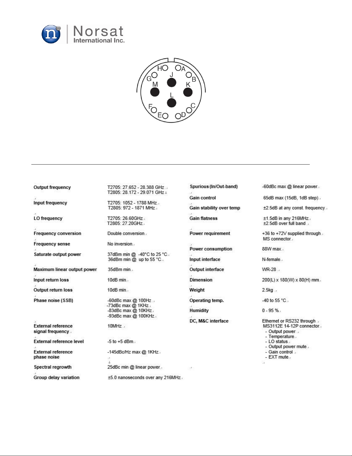
2.3 J3 / DC, M&C-------------------------------------------------------------------------------------------------- 7
CHAPTER 3. TECHNICAL SPECIFICATIONS-------------------------------------------------------------------- 8
3.1 SPECIFICATIONS SHEET--------------------------------------------------------------------------------- 8
3.2 OUTLINE DRAWING---------------------------------------------------------------------------------------- 9
CHAPTER 4. INSTALLATION--------------------------------------------------------------------------------------------10
4.1
UNPACKING ----------------------------------------------------------------------------------------------------------
10
4.2 INSTALLATION ON ANTENNA--------------------------------------------------------------------------- 10
4.3 CABLE INSTALLATION ------------------------------------------------------------------------------------ 11
4.4 WATERTIGHT SEALING UP OF CABLES AND CONNECTORS-------------------------------- 11
CHAPTER 5. EQUIPMENT OPERATION-------------------------------------------------------------------------- 12
5.1 USER SOFTWARE INSTALLATION-----------------------------------------------------------------------12
5.1.1 INSTALLATION REQUIREMENTS ----------------------------------------------------------- 12
5.1.2 INSTALLATION OF USER SOFTWARE----------------------------------------------------- 13
5.2 EQUIPMENT OPERATION-------------------------------------------------------------------------------- 15
5.2.1 DESCRIPTION OF THE USER SOFTWARE WINDOW --------------------------------- 15
5.2.2 SERIAL COMMANDS LIST--------------------------------------------------------------------- 18
5.2.3 SERIAL MODE OPERATION--------------------------------------------------------------------- 19
5.2.4 ETHERNET MODE OPERATION --------------------------------------------------------------- 21
5.2.5 BUC TURN-ON/OFF SEQUENCE------------------------------------------------------------ 23
CHAPTER 6. MAINTENANCE AND TROUBLESHOOTING -----------------------------------------------------24
6.1 MAINTENANCE--------------------------------------------------------------------------------------------------24
6.2 TROUBLE SHOOTING-----------------------------------------------------------------------------------------24
CHAPTER 7. WARRATY AND SERVICE INFORMATION------------------------------------------------------- 25
CHAPTER 8. CUSTOMER SERVICE----------------------------------------------------------------------------------26
APPENDIX ------------------------------------------------------------------------------------------------------------------ 27
A1. ACRONYMS ------------------------------------------------------------------------------------------------------27

Rev. 2.0
7005STC-O3B Series
DES007565
_____________________________________________________________________________________
4
1. INTRODUCTION
1.1 OVERVIEW
7005STC-O3B-A and 7005STC-O3B-B are highly reliable and innovative Block Up-converters (BUC)
specially designed for O3B satellite communication uplink system. This equipment converts the IF
signal (7005STC-O3B-A:1052-1788 MHz, 7005STC-O3B-B: 972-1871 MHz) to RF signal (7005STC-
O3B-A: 27.652-28.388 GHz, 7005STC-O3B-B: 28.172-29.071 GHz) with maximum linear output
power of 35dBm and saturated output power of 37dBm.
This manual provides the instructions necessary for operation and maintenance of 7005STC-O3B-A
and 7005STC-O3B-B. All user interfaces present in the BUC, as well as an exact description of the
diverse signals in the connectors of the BUC, will be described in this document. This manual also
explains the RS-232 and Ethernet communication interfaces for 7005STC-O3B-A and 7005STC-
O3B-B.
1.2 GENERAL DESCRIPTION
7005STC-O3B-A and 7005STC-O3B-B are comprised of IF, LO, Up-Converter, SSPA, and DC M&C as
shown Fig. 1.
IF Unit Converter Unit SSPA Unit
DC M&C Unit
Figure 1. Functional Block Diagram of Ka-band 5W BUC
DC/DCConverter
M&CProcessor
Filte
r
Filter
Filte
r
1st
LO
LO
Unit
2nd
LO

Rev. 2.0
7005STC-O3B Series
DES007565
_____________________________________________________________________________________
5
1.2.1 IF unit
IF unit amplifies the transmission signal from a remote modem and delivers it to the up-converter unit.
1.2.2 LO unit
LO unit generates two local signals to drive two LO ports of the up-converter using double conversion
structure.
1.2.3 Up-converter unit
Up-Converter converts the IF signal (7005STC-O3B-A:1052-1788 MHz, 7005STC-O3B-B: 972-1871 MHz)
to RF signal (7005STC-O3B-A: 27.652-28.388 GHz, 7005STC-O3B-B: 28.172-29.071 GHz) and also
filters out unwanted spurious and harmonics in front of SSPA. The BUC uses a double-conversion
technology to achieve better performance and cost-effective design.
1.2.4 SSPA unit
The main function of SSPA is to boost up the transmit power of the input signal to an expected level.
1.2.5 DC M&C unit
This board includes a DC/DC converter, regulators, and a EMI/EMC filter to make all kinds of DC voltages
required in the BUC. It also contains a Monitor and Control (M&C) function to monitor and control the
BUC, and communicate with a remote modem unit. The key parts for the M&C function are a
microprocessor and communication ICs for RS-232 and Ethernet.
1.3 IMPORTANT PRECAUTIONS
Read all the following instructions prior to using the BUC.
1.3.1 Reading Introduction
There is a potential safety risk unless appropriate precautions are taken while working with the BUC. All
the precaution and danger notes must be carefully read before using the BUC.
1.3.2 ESD Protection
The BUC contains elements sensitive to electrostatic discharges (ESD). It is important that the staff is
ground- connected while they are working with them.
1.3.3 Washing
Do not use liquid washing products or aerosols. Only use a damp cloth for cleaning.
1.3.4 Water and Humidity
Do not expose the BUC to standing water. Failure to follow this precaution could result in electric shock
and injury to persons.

Rev. 2.0
7005STC-O3B Series
DES007565
_____________________________________________________________________________________
6
1.3.5 Installation of the BUC
The BUC described in this manual should not be installed in an unstable situation because it may
cause serious injuries to the staff as well as a severe damage to the BUC.
1.3.6 Power Supply
An external power supply is necessary to convert the input AC 230V to +48V DC, and the internal
DC/DC converter within the BUC generates appropriate DC voltages for IF, LO, Up-converter, SSPA,
and DC M&C units.
1.3.7 Equipment Working Conditions
Never perform maintenance or make adjustments to the BUC when the power supply is connected.
1.3.8 Important Safety Information
Read the chapters on Installation and System Operation before attempting to switch on the BUC.
Do not connect the power port to a power source until all the other connections have been made.
Precautions
1.Do not operate the BUC without a cable or a RF load connected to the RF OUTPUT waveguide port.
2.Never look into the waveguide opening when the BUC is powered on.
2.INTERFACES
2.1 J1 / IF IN
N-type connector is used for the input port as shown in Fig. 2.
Figure 2. N-type IF and MS 12-pin connectors for Ka-band 5W BUC
MS 12-PIN
Connector
N-type IF
Connector
(Input)

Rev. 2.0
7005STC-O3B Series
DES007565
_____________________________________________________________________________________
7
2.2 J2 / RF OUT
WR28 waveguide is used for the output port as shown in Fig. 3.
Figure 3. WR28 RF output port for Ka-band 5W BUC
2.3 J3 / DC, M&C
MS 12-pin connector is used for the DC and M&C port as shown in Fig. 2, and its pin map and
interface are indicated in Table 1 and Fig. 4, respectively.
Table 1 Pin description for IF, RF, M&C connectors
Connector
Parameter
Description
J1
IF input connector
N-female, panel-mounted
Impedance
50 ohm
10MHz reference input
J2
RF output connector
WR28
J3
DC / M&C(Ethernet
or RS232)
Panel-mount (MS3112e14-12P)
J3-A
Ethernet Tx-
J3-B
Ethernet Tx+
J3-C
Ethernet Rx+
J3-D
Ethernet Rx-
J3-E
J3-F
RS-232 GND
J3-G
RS-232 TxD
J3-H
RS-232 RxD
J3-J
DC Power (+36 to +72V)
J3-K
DC Power return
J3-L
Mute @ High-Z or +5V
J3-M
Mute return (=RS-232 GND)
WR28 RF port
(Output)

Rev. 2.0
7005STC-O3B Series
DES007565
_____________________________________________________________________________________
8
Figure 4. Physical interface of MS 12-pin connector
3.TECHNICAL SPECIFICATIONS
3.1 SPECIFICATIONS SHEET

Rev. 2.0
7005STC-O3B Series
DES007565
_____________________________________________________________________________________
9
3.2 OUTLINE DRAWING
Figure 5. Mechanical outline for Ka band 5W BUC

Rev. 2.0
7005STC-O3B Series
DES007565
_____________________________________________________________________________________
10
4.INSTALLATION
This section of the manual is intended to provide aid in BUC installation.
4.1 UNPACKING
Perform an initial inspection upon receiving the BUC. You are advised to ensure the following:
•Check that the shipping container is not opened or damaged.
Have a representative from the shipping company present if you suspect that the
shipment is damaged or tempered with before opening the container.
•Check that all items in the packing list are present and undamaged.
•If any loss or damage is discovered, contact Norsat or a local representative before
proceeding.
•The shipping container and packing materials should be retained for possible reshipment.
Accessories for 7005STC-O3B-A or 7005STC-O3B-B are four waveguide adapter fixing screws,
an O-ring for the waveguide adapter.
4.2 INSTALLATION ON ANTENNA
7005STC-O3B-A and 7005STC-O3B-B have two M4 threaded holes at each side of BUC as shown
in Fig. 6 and these holes are used to fix the mounting bracket when used as stand-alone unit.
Please fix proper brackets to four fixing holes on the BUC before mounting the BUC to the antenna.
One of these fixing holes can be used to connect the BUC housing to the earth for grounding.
Fixing holes for mounting brackets
Figure 6. Location of fixing holes on Ka 5W BUC

Rev. 2.0
7005STC-O3B Series
DES007565
_____________________________________________________________________________________
11
The BUC has body and cover heat sinks with lots of air cooling fins for cooling. Therefore, to achieve
an optimal function of the BUC, it should be mounted upside down so that fins of the body heat sink
are open to fresh air as shown in Fig. 7. Ensure that there are no objects that obstruct a flow of fresh
air into the fins of the body heat sink.
Figure 7. Mounting position of Ka band 5W BUC
4.3 CABLE INSTALLATION
The connections of 7005STC-O3B-A or 7005STC-O3B-B must be done through a waveguide or
coaxial cables. The length of them must be adjusted depending on the installation. An inappropriate
choice of the interface waveguide or cable may result in either a reduction of output power at the
external unit or an excessive distortion of the signal.
Some guidelines to install the interface cables between the internal units (Power supply and
Modem) and the external unit (BUC) are as follows:
a) Make a plan with the minimal route to be followed by the cables. It is recommended
that 2m of additional cable is added for ease of maintenance.
b) Secure the cables at each end of the connection.
c) Ensure that the external connectors are waterproof as well as resistant to other agents.
4.4 WATERTIGHT SEALING UP OF CABLES AND CONNECTORS
The application of moisture-resistant tape over all the connectors is always recommended in every
type of outdoor installations because this ensures an appropriate waterproofing. The application
procedure of this tape is the following:
a) The application of moisture-resistant tape over the connectors is always recommended in
outdoor installations to ensure appropriate waterproofing. The application procedure of this
tape is the following: Ensure that all the connectors are correctly tightened. Cut a piece of
moisture-resistant tape with the desired size and remove the protector plastic of the tape.

Rev. 2.0
7005STC-O3B Series
DES007565
_____________________________________________________________________________________
12
b) Centre an end of the tape over the connector you want to protect and wrap tape tightly
and evenly over entire connector.
c) Repeat the steps above for all the connectors
5.EQUIPMENT OPERATION
5.1 USER SOFTWARE INSTALLATION
The user software is a Windows based Graphical User Interface (GUI) to monitor and control the
BUC (7005STC-O3B-A). It requires a dedicated LAN port or a PC serial port (COM port) to
communicate with the BUC. If your PC has no serial port, an USB to RS232 adaptor is necessary to
establish the connection (sold separately).
5.1.1 Installation Requirements
The user software installation requires Window XP or later versions with .NET Framework 4.0 pre-
installed on your PC. The following list shows the minimum system requirements for installation:
•PC with an available RS-232 serial communication port
•PC with an available RJ-45 LAN communication port
•Microsoft Windows XP or later versions with .NET Framework 4.0 installed
•1000MHz Processor
•RAM of 1024 MB
•Free hard disk space of at least 10 MB
•Monitor with 1024 x 768 screen resolution
•USB drive

Rev. 2.0
7005STC-O3B Series
DES007565
_____________________________________________________________________________________
13
5.1.2 Installation of the User Software
This GUI program is made up of just one executable file, ‘Ka 5W BUC GUI.exe’ but requires pre-
installed .NET 4.0 Framework. If .NET Framework is missing from your system, it can be
installed by running “dotnetfx40.exe”. After successful installation of the .NET 4.0 Framework, run
GUI program.
Figure 8. User software installation starting window.
Click on NEXT to continue.
You can accept the default settings for this installation.
Figure 9. (1) User software installation proceeding window

Rev. 2.0
7005STC-O3B Series
DES007565
_____________________________________________________________________________________
14
Figure 9. (2) User software installation proceeding window
Figure 9. (3) User software installation proceeding window

Rev. 2.0
7005STC-O3B Series
DES007565
_____________________________________________________________________________________
15
Figure 9. (4) User software installation completion window
Once the user software installation on your PC is completed, BUC GUI icon appears on
Windows START Menu and Desktop of your PC.
5.2 EQUIPMENT OPERATION ON USER SOFTWARE
5.2.1 Description of BUC GUI Window
When the BUC GUI icon is clicked, a BUC GUI window like Fig.10 pops up. Brief description of the
BUC GUI is as follows:
Figure 10. BUC GUI window for Ka band 5W BUC

Rev. 2.0
7005STC-O3B Series
DES007565
_____________________________________________________________________________________
16
①Serial Communication setting
You can set up serial communication
parameters. (Usable serial port number, baud
rate: 57600)
②UDP Communication setting
You can set up UDP communication
parameters. IP text box : BUC IP
TX : BUC UDP(Ethernet) Port
RX : Master UDP(Ethernet)
port
③Gain setting
This button is used to change the gain of the BUC.
④SSPA On function
This button is used to turn on the SSPA of the BUC.
⑤SSPA Off function (Mute)
This button is used to turn off the SSPA of the BUC.
⑥UDP Command
This text box is used to control the BUC with commands via UDP (Ethernet) communication. If
you click command list button(⑨), You can see the command list. (Refer to the serial
Commands list in 5.2.2)
⑦Serial Command
This text box is used to control the BUC with commands via serial communication. If you click
command list button(⑨), You can see the command list. (Refer to the serial Commands list in
5.2.2)
⑧DebugMode
This button is used to debug the BUC. It’s not used for operation.
⑨Command List
This button shows the command list. (Refer to the serial Commands list in 5.2.2)
⑩BUC Monitoring
This window shows the current status of BUC output power, temperature, LO lock status, over
temperature, over RF power, external mute.

Rev. 2.0
7005STC-O3B Series
DES007565
_____________________________________________________________________________________
17
⑪Status display window
This window shows the command processing result
⑫Clear
This button is used to clear status display window
⑬Firmware Version Display
Firmware major version number must match that of GUI. For example, if the firmware version
is 2.X, GUI program version should be 2.X.
⑭GUI Program Version Display.
.

Rev. 2.0
7005STC-O3B Series
DES007565
_____________________________________________________________________________________
18
5.2.2 Serial Commands List
Table 2. Serial Commands List
Item
Command
Example
Explanation
1
gst
gst
Get BUC status
2
sspaon
sspaon
Turn on SSPA
3
sspaoff
sspaoff
Turn off SSPA
4
sendipwr
sendipwr 192 168 100 3
Write master(PC) ip
5
sendiprd
sendiprd
Read master ip
6
sendportwr
Sendportwr 4001
Write master port
7
sendportrd
sendportrd
Read master port
8
ipwr
ipwr 192 168 100 15
Write BUC ip
9
iprd
iprd
Read BUC ip
10
portwr
portwr 4001
Write BUC port
11
portrd
portrd
Read BUC port
12
gwwr
gwwr 192 168 100 1
Write BUC gateway
13
gwrd
gwrd
Read BUC gateway
14
macwr
macwr 00 11 22 33 44 55
Write BUC MAC address
15
macrd
macrd
Read BUC MAC address
16
smwr
smwr 255 255 255 0
Write subnet mask
17
smrd
smwr
Read subnet mask

Rev. 2.0
7005STC-O3B Series
DES007565
_____________________________________________________________________________________
19
5.2.3 Serial Mode Operation
For serial mode operation, connect a prepared RS232 cable between the MS 12-pin connector on the
BUC and the PC serial port as shown in Fig. 11. Refer to Table1 and Fig. 4 for RS232 connection.
Figure 11. RS 232 connection between BUC and PC
Click BUC GUI icon on your PC and a BUC GUI window as shown in Figure 12 shows up, where you
can monitor and control the BUC. In this case, you can select only usable communication (COM) port
on BUC GUI window for connection.
Figure 12. BUC GUI window for operation

Rev. 2.0
7005STC-O3B Series
DES007565
_____________________________________________________________________________________
20
Select a usable COM port and the baud rate of 57,600 and click the open button. If the COM port is
open, BUC GUI will show a serial number (SERIAL NO), and the LED color for SERIAL changes from
red into green and Enable is marked as shown in Figure 13. BUC GUI starts reading status information
of the BUC periodically. And you can send control commands you want to the BUC by clicking proper
tabs such as MAX GAIN or SSPA ON or entering serial commands into the serial command text box
shown in Fig. 13.
Figure 13. BUC GUI window for RS 232 operation
This manual suits for next models
2
Table of contents
Other Norsat Media Converter manuals