Norsk Data ND-5000 ES C Series Owner's manual

Scanned by Jonny Oddene for Sintran Data © 2011
.
swung?
5
000
ES
1
EN
ND-
ND-
Moa’
[
C
Hardware
Mam/Manual
830
02.

Scanned by Jonny Oddene for Sintran Data © 2011
Scanned
by
Jonny
Oddene
for
Sintran
Data
©
2011

Scanned by Jonny Oddene for Sintran Data © 2011
ND—5
000
ES
Model
C
Hardware
MaintManua/
[VD-830102.]
EN
Scanned
bv
Jonnv
Oddene
for
Sintran
Data
©
2011
Scanned by Jonny Oddene for Sintran Data © 2011
NO
TE:
The
numbering
systemfor
Nors/e
Data
’s
documentation
changed
in
September
1988.
All
numbers
now
start
with
an
8.
The
numbering
structure
is
therefore
:\"D-8xxxxx..\'x
xx.
Example:
[VD-863018.314
EN.
Existing
manuals
will
receive
a
new
number
ifand
when
they
are
updated
or
revised.
The
information
in
this
manual
is
subject
to
change
without
notice.
Norsk
Data
A.S
assumes
no
responsibility/or
any
errors
that
may
appear
in
this
manual,
orfor
the
use
or
reliability
ofits
software
on
equipment
that
is
notfurnished
or
supported
by
Nors/e
Data
AS.
Copyright
1989
by
Nors/e
Data
AS
Send
all
documentation
requests
to
.'
Non/e
Data
A.S
Publication
Department
P.O.
Box
25
-
Bogerud
N—0621
Oslo
6
NOR
WA
Y
Scanned
by
Jonny
Oddene
for
Sintran
Data
©
2011

Scanned by Jonny Oddene for Sintran Data © 2011
(iii)
Preface
THE
PRODUCT
The
new
ND—SOOO
ES
Model
C
replaces
the
current
ND-SOOO
Oonpacts.
It
covers
the
low/medium
end
of
the
ND-SOOO
systems
and
is
meant
to
be
used
as
general
departemental
systems
and
servers
for
installations
that
are
not too
large.
THE
MANUEL
This
manual
covers
the
ND-SOOO
ES
Nbdel
C.
It
is
meant
to
be
a
helping
hand
for
the
service
staff.
The
manual
is
a
physical
description
and
does
NOT
cover
the
handling
of
system
errors,
test
program
descriptions
etc.,
as
these
are
described
in
other
manuals.
The
illustration
below
shows
which
manual
to
use
for
the
different
tasks:
<
ND—SOOO
ES
model
C)
(ND—5000.1'nodel
L
) (
ND—5000
ES
model
5
l
Physical
description
Physical
description
Physical
description
Test
programs
and
error
handling
MANUAL
ND—5000
Hardware
Maintenance
ND-805017
VANUAL
ND-SOOO
ES
Node]
C
MANUAL
ND—5000
as
Models
Hardware
Maintenance
Hardware
Maintenance
ND—
830102
ND—830103
MANUAL
ND—
100
Hardware
Maintenance
ND-SSOOOB
Scanned
bv‘Jonnv
Oddene
for
Sintran
Data
©
2011
Scanned by Jonny Oddene for Sintran Data © 2011
(iV)
'n-IE
READER
The
readers
of
this
manualsl'nuld
be
field
sewice
engineers
and
technical
personnel
directly
involved
in
maintaining
the
ND-SOOO
ES
Model
C.
RELATED
WINS
ND-lOO
Hardware
Maintenance
Manual
I‘D-830008
ND-SOOO
Hardware
Maintenance
DID-805017
Test
Program
Description
for
ND-lOO
NED-830005
ND—SOOO
Hardware
Description
ND—BOSOZO
'
dene
for
Sintran
Data
©
2011
Scanned by Jonny Oddene for Sintran Data © 2011
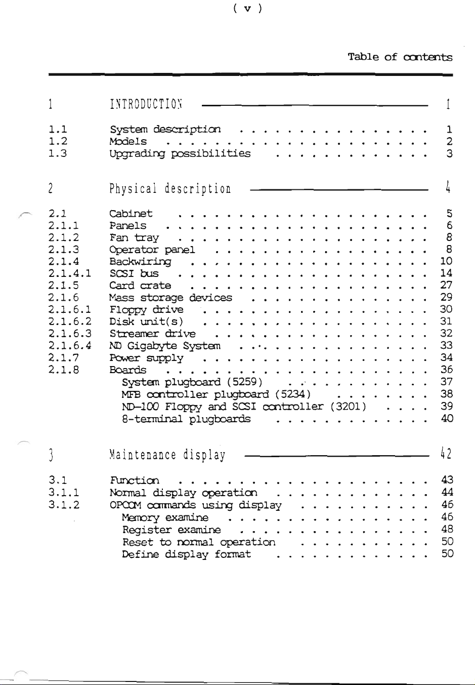
Table
of
0:11t
1
INTRODUCTION
1
1.1
Systemdesa‘iptiml
1.2
Models
.
.
.......
.
.
. . . . . . . .
.
2
1.3
Upgrading
possibilities
.
.
.
.
3
2
Physical
description
A
2.1
Cabinet
.
.....
.
..........
. . . .
5
2.1.1
Panels
.
.
.....
. .
.
...
.
.
.
. .
. .
. .
6
2.1.2
Fan
tray
. .
. .
.......
.
.
.......
.
8
2.1.3
Operator
panel
...
.
.
.
.
.......
...
.
8
2.1.4
Backwiring
.
..........
. .
. .
.
. .
.
.
10
2.1.4.1
SCSI
bus
.
.
.
.
.
............
. . . .
14
2.1.5
Cardcrate
. .
.......
....
. .
. .
.
. .
27
2.1.6
Massstoragedevices...............29
2.1.6.1
Floppy
drive
.
.......
.
.....
.
.
. . .
30
2.1.6.2
Disk
unit(s)
......
.
.
...
.
.
.
.
. . . .
31
2.1.6.3
Streamer
drive
.
.
. . . .
.
. . . . . .
.
.
.
. .
32
2.1.6.4
ND
Gigabyte
System
.
.‘
........
.....
.
33
2.1.7
Power
supply
.........
...
.
. . . .
.
.
34
2.1.8
Boards..............
......
..36
Systemplugboard(5259)
.........37
MFBoontroller
plugboard
(5234)
.
. .
. .
. .
38
ND-lOO
Floppy
and
SCSI
oautmller
(3201)
.
.
. .
39
8-terminalplugboards
.....4O
3
Maintenance
display
1:2
3.1
Function”
.....
..............43
3.1.1
Normaldisplayoperaticn
44
3.1.2
OPCINoannandsusing
display
. .
.....
. .
. .
46
Mermryexamine
.....
............46
Registerexamine..
............48
Resettommaloperation
50
Definedisplayfonnat
.............SO
,
'
nData©2011

Scanned by Jonny Oddene for Sintran Data © 2011
(vii)
Table
of
appendices
Appendix
A:
Part
numbers
32
Index
33
Scanned
by
Jonny
Oddene
for
Sintran
Data
©
2011
Scanned by Jonny Oddene for Sintran Data © 2011
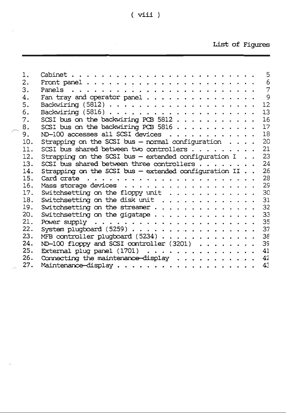
(viii)
Listof
Figures
\OEDQO‘UIIDOONl—l
Cabinet...............
Prontpanel..
......
Panels.
......
Fantrayandooperatorpanel...
Backwiring(5812).
Backwiring
(5816)..
.
SCSI
bus
on
the
backwiring
P03
5812
.
SSI
bus
on
the
backwiring
PS
5816
.....
.
ND—lOO
accesses
all
SS1
devices
. .
.
Strapping
on
the
SS1
bus-
normal
configuration
SS1
bus
shared
between
two
controllers
.
Strapping
on
the
SSI
bus—
extended
configuration
I.
SSI
bus
shared
between
three
controllers
.
Strapping
on
the
SSI
bus-
extended
configuration
II
Card
crate
.
. .
. .
. .
Mass
storage
devices
.
. . .
Switchsetting
on
the
floppy
unit.
. .
Switchsettingontnedisk
unit
. .
.
Switchsetting
on
the
streamer
.
.
Switchsetting
on
the
gigatape
.
Power
supply
......
.
. .
System
plugboard
(5259).
. . . .
MFB
controller
plugboard
(5234)..
.
ND—lOO
floppy
and
SS1
controller
(3201)
External
plug
panel
(1701)
...
.
Cormectingthemaintenance—display
.
...
Maintenance—display
.........
a
Scanned
by
Jonny
Oddene
for
Sintran
Data
©
2011

Scanned by Jonny Oddene for Sintran Data © 2011
List
of
Tabla
Modeloverview.....................2
Upgradingpossibilities.................
3
Scanned
by
Jenny
Oddene
for
Sintran
Data
©
2011
Scanned by Jonny Oddene for Sintran Data © 2011
Chapter
1
INTRODUCTION
This
chapter
gives
an
introduction
to
the
ND-SOOO
ES
C
models.
1.1
System
description
The
new
ND—SOOO
ES
Model
C
replaces
the
current
ND-SOOO
Compact.
It
covers
the
low/medium
end
of
theND—SOOO
systemsandismeanttobeusedas
general
departmental
systems
and
servers
for
installations
that
are
not too
large.
It
has
the
same
cabinet
as
the
previous
version,
except
for
the
front
cover.
The
interior,
however,
is
completely
new.
It
consists
of
a
large
card
crate,
into
which
all
cards
and
devices
(including
the
new
power
supply,
the
fan
unit,
disks,
floppy
units
and
streamer
units)
can
be
plugged.
The
backwiring
is
located
in
the
middle
of
the
card
crate,
and
cards
and
devices
are
plugged
in
from
both
the
front
and
the
rear
sides.
The
new
ND-SOOO
ES
Nbdel
C
is
available
with
all
ND-SOOO
CPU
versions,
including
NIB-5800.
Seethetablempageoranoverviewofthe
various
systems
available.
Scanned
by
Jonny
Oddene
for
Sintran
Data
©
2011
Scanned by Jonny Oddene for Sintran Data © 2011
2
adapter
1
INTRODUCTION
-1.2
Models
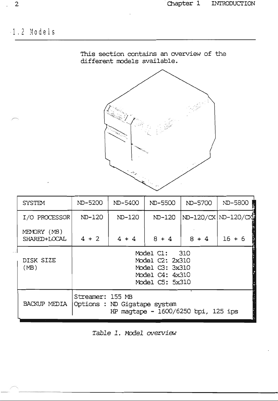
This
section
contains
an
overview
of
the
different
models
available.
SYSTEM
ND-SZOO
ND—54OO
ND-SSOO
ND-S7OO
ND-SBOO
.-
I/O
PROCESSOR
ND-lZO
ND—lZO
ND-lZO
ND-lZO/CX
ND-lZO/o
:
MEMORY
(MB)
SHARED+LOCAL
4+2 4+4
8+4
8+4
l6+6
Model
Cl:
310
DISK
SIZE
Model
C2:
2x310
(MB)
Model
C3:
3x310
Model
CA:
4x310
Model
CS:
5x3lO
Streamer:
155
MB
BACKUP
MEDIA
Options
:
ND
Gigatape
system
HP
mag-tape
-
1600/6250
bpi,
12S
ips
Table
1.
Model
overview
Scanned
by
Jonny
Oddene
for
Sintran
Data
©
2011

Scanned by Jonny Oddene for Sintran Data © 2011
-
>.flr-
Chapter
1
INTRODUCTION
.
3
1.3
Upgrading
possibilities
Full
upgrading
is
possible
between
the
ND-SOOO
ES
Nbdel
C
systems:
0
Upgrading
between
models,
for
example
upgrading
an
ND—SZOO
Model
C1
to
an
ND-SZOO
Model
C5.
'
o
Upgrading
between
systems,
for
example
upgrading
an
NIB-5200
to
an
MID—5700.
Note
that
extra
memory
boards
are
not
included
in
the
upgrading
kits,
and
must
therefore
be
ordered
separately.
ND-SZOO
NIB-5400
ND-SSOO
ND—57OO
NIB-5800
Model
Cl——o
Model
Cl—
Model
Cl—
Model
Cl——-
Model
c1
'
Model
c2—
Model
cz—
Model
cz—o
Model
c2—~
Model
(:2
‘1;
Model
cs—o
Model
c2—
Model
c3—
Model
c3—
Model
c3
f
Model
04—.
Model
04—.
Model
c4—
Model
c4—
Modél
c4
."-c
15"
"an!
at“
.
‘L
Model
c5—.
Model
c5—
Nbdel
c5—
Model
c5—.
Model
c5
‘
a"
Table
2.
Upgrading
possibilities
Scanned
by
Jonny
Oddene
for
Sintran
Data
©
2011
Scanned by Jonny Oddene for Sintran Data © 2011
ChapterZ
Nwsicaldescflption
This
chapter
describes
the
different
parts
of
the
hardware
in
the
new
ND—SOOO
ES
Model
C.
This
is
a
physical
description,
and
will
not
cover
functional
descriptions
of
the
different
parts
described
in
this
chapter:
Cabinet
Panels
Power
switch
Backwiring
Fan
tray
Operator
panel
Card
crate
Plug-in
modules
i_'
'
nD
©2m1
“

Scanned by Jonny Oddene for Sintran Data © 2011
Chapter
2
Physical
description
5
2.1
Cabinet
This
section
describes
the
cabinet,
including
the
card
crate,
the
power
supply
and
the
devices.
...“V
-4
‘
It
is
easy
to
replace
defective
devices
and
nodules,
as
the
parts
that
normally
need
service
are
plugged
directly
into
the
backwiring
and
the
cabinet
is
practically
free
from
internal
cables.
Figure
1
.
Cabinet
m
Scanned
by
Jonny
Oddene
for
Sintran
Data
©
2011

Scanned by Jonny Oddene for Sintran Data © 2011
6
Chapter
2
Physical
description
2.1.1
Panels
This
section
shows
how
to
remove
the
panels.
Front
panel
Remove
the
screw
located
at
the
top
of
the
panel.
Lift
the
panel
slightly
and
pull
it
away.
Figure
2.
Front
panel
7*
'
e
7
,,
—$canned_by_Jonny_Oddenn
fnr
Qintmn
Data
©
2011
Scanned by Jonny Oddene for Sintran Data © 2011
Chapter
2
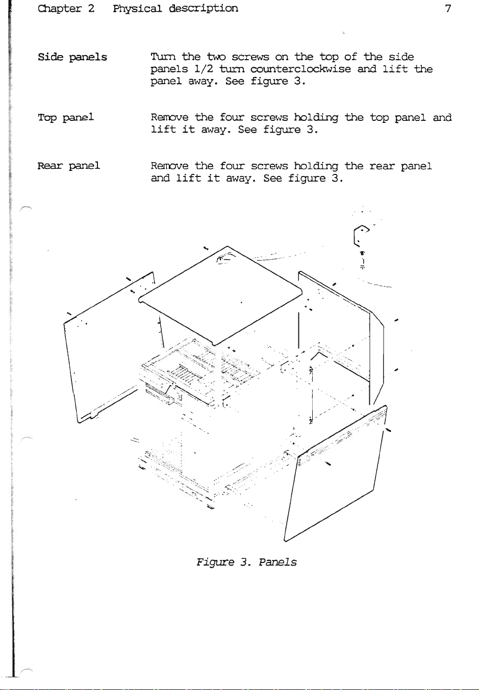
Side
panels
Toppanel
Rear
panel
Physical
description
7
'I‘urn
the
two
screws
on
the top
of
the
side
panels
1/2
turn
counterclockwise
and
lift
the
panel
away.
See
figure
3.
Remove
the
four
screws
holding
the top
panel
and
lift
it
away.
See
figure
3.
Remove
the
four
screws
holding
the
rear
panel
and
lift
it
away.
See
figure
3.
Figure
3
.
Panels
Scanned
by
Jonny
Oddene
for
Sintran
Data
©
2011

Scanned by Jonny Oddene for Sintran Data © 2011
8
'
Chapter
2
Physical
description
2.1.2
Fan
tray
The
cooling
is
based
on
the
same
principle
as
the
previous
ND-SOOO
Ccmpact.
The
fans
are
located
in
a
fan
tray
plugable
from
the
bottom
of
the
front
into
the
backwiring
(see
figure
4).
The
fans
are
the
DC
type,
with
an
extra
wire
for
indicating
the
rotation
speed.
The
power
for
the
fans
is
supplied
by
the
DC
500
power
supply,
and
the
voltage
is
controlled
by
software
and
the
ambient
temperature.
The
input
to
the
fan
speed
control
canes
from
an
NTC
resistor
which
senses
the
roan
temperature.
This
sensor
is
mounted
at
the
top
of
the
backwiring,
close
to
the
air
inlet.
NOTE
Note
that
you
must
turn
the
power
off
before
removing
or
inserting
the
fan
tray.
2.1.3
Operator
panel
The
operator
panel
and
key
switch
are
located
at
the
top
of
the
front
(see
figure
4).
It
is
similar
to
the
operator
panels
on
previous
ND
computers,
but
the
display
has
been
removed.
The
information
that
earlier
could
be
read
frcm
the
display
is
still
available,
but
you
must
connect
a
maintenance
display
to
get
it
(see
page
42).
The
operator
panel
is
connected
to
the
backwirihg
via
a
flat
cable
along
the
top
of
the
cabinet.
Scanned
by
Jonny
Oddene
for
Sintran
Data
©
2011

Scanned by Jonny Oddene for Sintran Data © 2011
.-.
4
‘V._....._'..._.
chapter
2
Physical
description
Figure
4.
Fan
tray
and
operator
panel
Scanned
by
Jonny
Oddene
for
Sintran
Data
©
2011
Scanned by Jonny Oddene for Sintran Data © 2011
10
Chapter
2
Physical
description
I
‘
. .
2.1.4Bacnw1r1ng
The
backwiring
acts
as
the
main
connection
between
all
internal
modules.
All
cards
and
devices
are
plugged
directly
into
the
backwiring,
including
the
power
supply
and
the
fan
tray.
The
backwiring
also
contains:
0
Temperature
sensor
(regulating
the
fan
Speed)
0
Connector
for
the
operator
panel
0
An
area
where
it
is
possible
to
measure
the
voltages
o
Terminator/strap
fields
for
the
SCSI
bus
0
Switches
for
splitting
the
SCSI
bus
The
backwiring
is
prepared
for
taking
care
of
the
internal
SCSI
bus.
This
bus
has
been
routed
to
all
internal
SCSI
devices,
and
it
ends
up
on
the
plugboard
in
position
14.
Here
the
bus
can
be
terminated,
or
one
external
single-
ended
SCSI
device
can
be
connected.
This
could,
for
example,
be
a
magtape
unit
used
for
backup.
bkmmally
all
devices
on
the
SCSI
bus
can
be
accessed
from
ND-lOO,
but
the
strap/terminator
fields
and
the
split
switches
on
the
backwiring
make
it
possible
to
split
the
SCSI
bus.
See
the
description
in
the
section
"SCSI
bus"
on
page
14.
Two
different
versions
of
the
backwiring
are
used:
0
PCB
number
5812
for
early
versions
0
PCB
number
5816
for
later
versions
The
difference
between
these
two
backwirings
is
the
possibility
to
split
the
bus
with
Scanned
by
Jonny
Oddene
for
Sintran
Data
©
2011
This manual suits for next models
25
Other Norsk Data Desktop manuals


