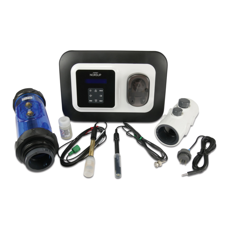
Norsup NORSUPONE Operation instructions

CONTROLLER & LOW
SALT ELECTROLYSE UNIT
TYPE NORSUPONE
ORIGINAL MANUAL
Item nr. 7028001 / 7028005

23
Alterations which serve the technological progress as well as errors excepted! ORIGINAL MANUAL NORSUPWWW.NORSUP.EU Alterations which serve the technological progress as well as errors excepted!
CONTROLLER & LOW SALT ELECTROLYSE UNIT TYPE NORSUPONECONTROLLER & LOW SALT ELECTROLYSE UNIT TYPE NORSUPONE
EN
TABLE OF CONTENTS
Google Play Store Apple Appstore
DOWNLOAD NORSUPONE APP: www.norsup.eu
Errors and technical modifications subject
to change, reproduction as well as electronic
duplication only with our written permission.
© NORSUP
Edition: 11.2020
E. CHEMICAL SUBSCRIPTION 32
E.1 Accessing the system 32
E.2 work flow 32
E.3 Staff login 32
E.3.1 Staff dashboard 32
E.3.2 To add products 32
E.3.3 To view the product details 33
E.3.4 To edit product details 33
E.3.5 To delete a product 34
E.3.6 To view the installer list 34
E.3.7 To view staff 34
E.3.8 To view the subscription 35
E.3.9 To confirm the invoice of the order 35
E.3.10 To view purchase order 35
E.3.10.1 To view orders from customers 35
E.3.10.2 To view orders to Megagroup 36
E.3.11 To view device purchase order 36
E.3.12 To add device purchase order 36
E.4 Installer login 37
E.4.1 Dashboard 37
E.4.2 To view customer list 37
E.4.3 To invite customer 37
E.4.4 To view subscriptions 38
E.4.5 To view orders 38
E.4.6 Purchase order 38
E.4.6.1 Orders from customers 38
E.4.6.2 Orders to customers 38
E.4.7 To generate order 1 39
E.4.7.1 To automatically generate the
purchase order 40
E.5 Customer login 40
E.5.1 Customer dashboard 40
E.5.2 To view pools list 40
E.5.3 To add pool 41
E.5.3.1 To view pool details 41
E.5.3.2 To edit pool 42
E.5.3.3 To delete pool 42
E.5.4 To add subscription 42
E.5.4.1 To view subscription 43
E.5.4.2 To edit subscription 44
E.5.4.3 To cancel subscription 44
E.5.5 To shop 44
E.5.6 Orders 45
E.5.7 Devices 46
E.6 mobile application login 46
E.6.1 To add pool 46
E.6.2 To edit pool 47
E.6.3 To delete pool 48
E.6.4 To add subscription 48
E.6.5 To edit subscription 49
E.6.6 To unsubscribe 50
E.6.7 To shop 50
E.6.8 Orders 52
F. MAINTENANCE 52
F.1 Maintenance of the hydraulic circuit 52
F.2 Probe maintenance 52
F.3 Lifespan of the prob 52
F.4 Maintenance of other probes 52
F.5 Special cases 52
F.6 Troubleshooting guide 53
F.6.1 Calibration
53
F.6.2 Flow detection 53
F.6.3 Tank level 53
F.6.4 Smart mode 53
F.6.5 Leds mother board switch off 53
F.6.6 Reset wifi 53
F.6.7 Dustomer service 53
F.7 Terms of use 53
F.7.1 Object
53
F.7.2 The instructions 53
F.7.3 Updates
54
F.7.4 Sensors 54
F.7.5 Garanties
54
F.7.6 Nomadic mode 54
F.7.7 Intellectual property 54
F.7.7 Personal data 54
F.7.8 Archiving – proof 54
F.7.9 User acceptance 55
F.7.10 Litigation 55
A. HARDWARE INFORMATION 4
1 GENERAL INFORMATION 4
A.1.1 Overview 4
A.1.2 Warnings 4
2 INSTALLATION 5
A.2.1 Description 5
A.2.2 Control box 5
A.2.3 Relay box 5
A.2.4 Electrical installation and wiring 5
A.2.4.1 Powering the controller 5
A.2.4.2 Connections of sensors to control box 5
A.2.4.3 Connection of heat pump 6
A.2.4.3.1 Heat pump parameters 6
A.2.4.4 Connection of variable speed pump 7
A.2.4.4.1 Variable speed pump parameters 7
A.2.4.5 Connection of a chlorinator /
acid dose pump (modbus) 8
A.2.4.6 Connection of pool lamp 8
A.2.5 Connecting control box and relay box 8
A.2.6 Chemical water balance 9
A.2.7 Reset wi-fi/putting controller to ap mode 9
B. USER CREATION 10
B.1 To invite staff 10
B.2 To invite installer 11
B.3 To invite supplier 12
B.4 To invite customers 13
C. NORSUPONE IOT APPLICATION 14
C.1 Installer login 14
C.2 Dashboard 14
C.3 Customer 14
C.3.1 To add controllers under a customer in
installer login 14
C.3.2 To view the controller details (devices
and sensors under the controller) 16
C.4 Critical alarms 16
C.4.1 To view the customer contact detail 16
C.4.2 To filter the alarm list 16
C.4.3 To view the regions where
the alarms triggered 17
C.4.4 Resolved alarms 17
C.5 Customer login 17
C.6 To customize the dashboard 18
C.7 To add sensors and devices under a controller 18
C.7.1 To add smart light 18
C.7.2 Controlling the smart light 19
C.7.2.1 To add timer slot 19
C.7.3 To add heat pump 21
C.7.4 Controlling the heat pump 21
C.7.5 To add variable speed pump 21
C.7.6 Controlling the variable speed pump 21
C.7.7 To add salt chlorinator 21
C.7.8 To reset acid level volume for
salt chlorinator 21
C.7.9 Controlling the salt chlorinator 22
C.7.10 To add temperature sensor 22
C.7.11 To add ph electrode 24
C.7.12 To calibrate the ph sensor 24
C.7.13 To add orp/ec electrode 24
C.7.14 To calibrate the orp/ec sensor 24
C.8 Alarms 25
C.9 To invite guest 25
C.10 Reset wi-fi 25
C.11 Sign out 26
D. WARRANTY INFORMATION 26
D.1 Process flows 26
D.2 Work flow 26
D.3 Staff login 26
D.3.1 Add device purchase order 26
D.3.2 Edit purchase order 27
D.3.3 Delete device purchase order 27
D.4 Supplier sign in 28
D.4.1 Generate qr code 28
D.4.2 Download excel template 29
D.5 Customer login 29
D.5.1 To add products by a customer 29
D.5.2 To add products by an installer 30
D.5.3 To add bill through web application
by customer 31

45
Alterations which serve the technological progress as well as errors excepted! ORIGINAL MANUAL NORSUPWWW.NORSUP.EU Alterations which serve the technological progress as well as errors excepted!
CONTROLLER & LOW SALT ELECTROLYSE UNIT TYPE NORSUPONECONTROLLER & LOW SALT ELECTROLYSE UNIT TYPE NORSUPONE
EN
2 INSTALLATION
A.2.1 DESCRIPTION
The NorsupOne kit can be delivered with
• Control box
• Relay box
A.2.2 CONTROL BOX
All the connectors are in this box, it allows you to
connect the probes and the relay box or boxes. Wifi,
ethernet, a 4 GB hard drive and 512 MB of memory are
installed by default. It offers total autonomy even
without internet with its own interface, onboard
software and all pool and spa automation.
Fig. 1: Control Box
A.2.3 RELAY BOX
It is made up of 8 numbers of 8A relays, and a
connector to connect it to the control box. These
relays can supply small equipment, metering pumps,
lights, dry contacts or supply power contactors for
larger equipment (filtration, heating, jet ...)
Fig. 2: Relay box
A.2.4 ELECTRICAL INSTALLATION AND WIRING
A 2.4.1 POWERING THE CONTROLLER
Two ports on top right of the controller are for the
powering (Neutral and Live)
Fig. 3: Powering of control box
A.2.4.2 CONNECTIONS OF SENSORS TO
CONTROL BOX
Here we are connecting pH, ORP, Electrical
conductivity and temperature probe to control box
• Connect 3 wires of PT100 temperature sensor to the
U26 connector (Port 4 from right), red wire on the
left, the other 2 on the right whatever the direction.
• Connect flow detector on terminal block 7 to 12.
• Connect the BNC Connectors of ORP, pH and Electrical
conductivity probe respectively to the BNC input on
the control station as given in the below image.
Fig. 4: Connection of ORP, pH, EC and Temperature
sensor to the control box
You can also connect the sensors to Salt chlorinator
(If you are using) as shown in the figure below.
Fig. 5: Connection of ORP, pH, EC and Temperature
sensor in the accessory holder
A. HARDWARE INFORMATION
A.1 GENERAL INFORMATION
A.1.1 OVERVIEW
NorsupOne is an intelligent controller, equipped with
sensors and actuators around software specifically
developed for swimming pools and spas. NorsupOne
manages all types of treatment and water balance,
filtration, heating, roller shutters, lighting, led pulsed
lighting. A total of 15 actuators are possible.
The registration date corresponds to the creation of
the customer account on the NorsupOne registration
platform. The use of a NorsupOne home automation
controller implies the acceptance of the general
conditions of use.
When powering up, all relays light up to verify that all
of the signal wiring is correct. In case of doubt put all
devices in the OFF position on the user interface and
replug the relays, then carry out an ignition test of
each device and check that each relay triggers the
connected equipment.
During installation you must ensure that you comply
with the following points, to guarantee a correct
installation.
• A relay cannot control a power higher than 8A (1500 W)
• For higher powers, a power contactor is installed.
• Scrupulously respect the polarities of the Modbus
sensors, probes and buses.
• Respect the electrical standards for protection and
power of the circuit breakers.
• Connect an equipotential bonding to the hydraulic
circuit before filtration, in series with the earth
intended for the devices.
(If in doubt, contact your service representative or
your licensed electrician)
The mobile application of NorsupOne will enable the
installer and the customer to control devices and
sensors using IoT Flowers via IoT Flowers cloud service
and the web application enables the installer to
monitor the activities.
A.1.2 WARNINGS
Failure to follow these instructions may result in
serious injury or death
• The appliance is intended for swimming pools and
spas only the installation of the appliance must be
carried out by a person with proven and certain skills
in electricity and hydraulics
• Disconnect the appliance from the mains supply
before carrying out any work.
• All electrical connections must be made by a qualified
professional electrician and in accordance with the
standards in force in the country of installation.
• Make sure that the appliance is connected to an outlet
protected against short-circuits. The device must also
be supplied via an isolation transformer or a residual
current differential device (DDR) whose nominal
residual operating current does not exceed 30 mA.
• Ensure that children cannot play with the device. Keep
your hands and all foreign objects away from openings
and moving parts. In particular, make sure there is no
contact with electronic cards and power cables.
• Check that the supply voltage required by the
product corresponds to that of the distribution
network and that the supply cables are suitable for
the current supply of the product.
• Chemicals can cause internal and external burns. To
avoid death, serious injury and / or property damage:
Wear personal protective equipment (gloves, glasses,
mask ...) when servicing or maintaining this device.
This device must be installed in a sufficiently ventilated
room, protected from humidity and without contact
with splashes of water or other liquid.
• To reduce the risk of electric shock, do not use an
extension cord to connect the appliance to the
mains. Use a wall outlet.
• Read the instructions in this manual and the
instructions on the device carefully. Failure to comply
with the instructions and recommendations could
cause damage. This document must be given to any
end user, who will keep it in a safe place.
• This device can only be used by children under 18
years of age or by people with reduced physical,
sensory or mental capacities or lack of experience or
knowledge, only if they (if they) are properly
supervised (e) s or if instructions relating to the safe
use of the device have been given to them and if the
risks involved have been understood. Children should
not play with the device. Cleaning and user
maintenance must not be carried out by children
without supervision.
• If the power cable is damaged, it must be replaced
by the service provider originally installed, its after-
sales service or by persons of similar qualifications,
in order to avoid danger. Electric shock may occur.
ELECTRICAL CONNECTION STANDARDS
• F NF C 15-100
• GB BS7671:1992
• D DIN VDE 0100-702
• EW SIST HD 384-7-702.S2
• A ÖVE 8001-4-702
• H MSZ 2364-702:1994 / MSZ 10-533 1/1990
• E UNE 20460-7-702 1993, REBT ITC-BT-31 2002
• M MSA HD 384-7-702.S2
• IRL IS HD 384-7-702
• PL TS IEC 60364-7-702
• I CEI 64-8/7
• CZ CSN 33 2000 7-702
• LUX 384-7.702 S2
• SK STN 33 2000-7-702
• NL NEN 1010-7-702
• SLO SIST HD 384-7-702.S2
• P RSIUEE
• TR TS IEC 60364-7-702

67
Alterations which serve the technological progress as well as errors excepted! ORIGINAL MANUAL NORSUPWWW.NORSUP.EU Alterations which serve the technological progress as well as errors excepted!
CONTROLLER & LOW SALT ELECTROLYSE UNIT TYPE NORSUPONECONTROLLER & LOW SALT ELECTROLYSE UNIT TYPE NORSUPONE
EN
A.2.4.3 CONNECTION OF HEAT PUMP
Only 2 wires are needed to do the Modbus connection
between the Heat Pump and the controller: A and B
(Black and Blue as shown in the image) on the port
2-3 of the RS485 connector on the controller(U12). The
heat pump will automatically stop if the temperature
goes below 10ºC.
Fig. 6: Connection of heat pump from heat pump
board to the Control box
• For a length of less than 20 meters, use a crossover
cable of telecom type, strip a pair and connect one of
the pairs to A and the other to B on port U12.
• On the NorsupOne app, the port number 16 (In
Modbus) is booked for the NorsupOne heater.
A.2.4.3.1 HEAT PUMP PARAMETERS
• Press on the Settings icon on the screen, number
pad will be displayed
• Enter the password 066 and tap on the Enter icon,
System Parameters will be displayed
• Tap on the next arrow till it reach parameter H37, tap
on the Unit address, number pad will be shown
• Enter 50 and tap on the enter icon
• Tap on the back arrow at the left top of the screen to
go back to the normal screen
Fig. 7: Shows parameters setting process
Fig. 8: Shows the Back arrow
A.2.4.4 CONNECTION OF VARIABLE SPEED PUMP
• The ports 13 to 15 of controller (refer figure 10)
corresponds to speed 1, 2 and 3 of variable speed
pump and must be linked to the relay box to any
of the 8 ports (+ the power wire which is port 16)
Fig. 9: Connecting wires of Variable speed pump
Fig. 10: Variable speed pump connection to relay board
• Bridge the red on the 3 NC ports of the 3 selected relays.
Bridge black on the 3 COMMON ports of the 3 relays.
Insert each colour into one of the NO ports, respecting
the numbers of the start connector on the control board.
• Connect the pump power to a suitable power
contactor with START / STOP trigger.
• On the NorsupOne app, the port number 13 (U20) is
booked for the Variable Speed Pump.
A.2.4.4.1 VARIABLE SPEED PUMP PARAMETERS
Once we connected the variable speed pump to the
replay box and controller, we need to change the
mode of the variable speed pump as given below.
• Press on the SET button until the SET UP shows on
the screen.
• Use set till the screen shows E.
• Press on the down arrow to change that to On.
• Press SET and then on the down arrow.
• Press set twice, the STORE option will be shown on
the screen.
Fig. 11: Variable speed pump parameter setting steps
PAC Description Norsup
One
Type
A3 RS485 - A+ signal Acrossed
B3 RS485 - B- signal Bcrossed
GND common ground - 0V GND nc
NC 12 volts +12v do not
connect
NOM Description Bor-
nes
Color
V1 Low pump speed (V1) 13 Brown (Br)
V2 Average pump speed (V2) 14 Green (V)
V3 High pump speed (V3) 15 White (BI)
CCommon COM Black (N)
D Start/Stop NC Red (R)

89
Alterations which serve the technological progress as well as errors excepted! ORIGINAL MANUAL NORSUPWWW.NORSUP.EU Alterations which serve the technological progress as well as errors excepted!
CONTROLLER & LOW SALT ELECTROLYSE UNIT TYPE NORSUPONECONTROLLER & LOW SALT ELECTROLYSE UNIT TYPE NORSUPONE
EN
A.2.4.5 CONNECTION OF A CHLORINATOR ACID
DOSE PUMP MODBUS
If you have Modbus intelligent chlorinator, with its
own algorithms, connect it to the ModBus U12 port
(Red and Green wires, as given in the image). Your
controller will carry out the security checks (flow, min
and max of the PH and ORP sensors, commissioning
of the filtration). Apart from these points, Chlorinator/
acid pumps duo device will define its own course.
Fig. 12: Connection of Salt Chlorinator to the Control box
Fig. 13: Shows the Salt Chlorinator
If one or more devices are being connected to the
Modbus RS485 the then the connection should be in
series as shown in the below diagram.
A.2.4.6 CONNECTION OF POOL LAMP
Connect two cables of light into NO and COM ports of
relay box as shown in the image below. And connect
the corresponding communication cable from relay
box to control box (port number 12).
Fig. 14: Connection of Pool Lamp to the Relay box
A.2.5 CONNECTING CONTROL BOX AND RELAY BOX
Fig. 15: Connection between Control box and Relay box
Fig. 16: Control box and relay box in the actual set up
A.2.6 CHEMICAL WATER BALANCE
The water must be balanced manually BEFORE the
device is started up. The following table summarizes
the concentrations recommended by NorsupOne.
Your water should be checked regularly to maintain
these concentrations and minimize surface corrosion
or deterioration.
A.2.7 RESET WIFIPUTTING CONTROLLER TO AP MODE
• Click for 12 seconds on the R-WIFI push button (S1).
• led D2 flashes quickly
RELAY BOXCONTROL BOX
CHEMISTRY Recommended
CONCENTRATIONS
Free chlorine 1.0 to 3.0 ppm
pH 7.2 to 7.6
Cyanuric acid
(Stabilizer)
20 to 30 ppm max.
(Add stabilizer only if
necessary) 0 ppm in
indoor pool
Total alkalinity 80 to 120 ppm
Water hardness 200 to 300 ppm
Metals 0 ppm.

10 11
Alterations which serve the technological progress as well as errors excepted! ORIGINAL MANUAL NORSUPWWW.NORSUP.EU Alterations which serve the technological progress as well as errors excepted!
CONTROLLER & LOW SALT ELECTROLYSE UNIT TYPE NORSUPONECONTROLLER & LOW SALT ELECTROLYSE UNIT TYPE NORSUPONE
EN
B.2 TO INVITE INSTALLER
The installers will be added in the
AX and all the installers have an AX
id. The staff should enter the email
id (Used to create AX id), AX id and
the shop id on the respective fields
to invite the installer.
B. USER CREATION
Staff, Installer, Supplier and
Customers are main users come
under the NorsupOne application.
The staff will be from the Megagroup
and staff has authority to invite the
Installer and the Supplier. Installer is
the person who invites the Customer.
B.1 TO INVITE STAFF
The Megagroup admin can invite
the Staff.
• Click on the Customer option,
choose Staffs
• Click on Invite Staff and enter the
staff’s email address
• Click on Invite
B.2 TO INVITE INSTALLER
The installers will be added in the
AX and all the installers have an AX
id. The staff should enter the email
id (Used to create AX id), AX id and
the shop id on the respective fields
to invite the installer.
Fig. 17: Shows the Customer option Fig. 21: Shows the Customer option
Fig. 18: Shows the Staff option Fig. 22: Shows the Installer option
Fig. 19: Shows the Invite Staff option Fig. 23: Shows the invite Installer option
Fig. 20: Shows the field to enter the email Id and the Invite option Fig. 24: Shows the field to enter the installer details and the invite option

12 13
Alterations which serve the technological progress as well as errors excepted! ORIGINAL MANUAL NORSUPWWW.NORSUP.EU Alterations which serve the technological progress as well as errors excepted!
CONTROLLER & LOW SALT ELECTROLYSE UNIT TYPE NORSUPONECONTROLLER & LOW SALT ELECTROLYSE UNIT TYPE NORSUPONE
EN
B.4 TO INVITE CUSTOMERS
The installer can invite the customer
by entering their email id on the
respective field. Installer can use
both mobile and web application
to invite the customers.
B.3 TO INVITE SUPPLIER
The staff can invite the supplier by
entering their email id and shop id
on the respective field.
Fig. 25: Shows the Supplier option Fig. 28: Shows the steps of inviting a customer
Fig. 26: Shows the Invite Supplier option Fig. 29: Shows the Customer option
Fig. 27: Shows the field to enter the Supplier details and Invite option Fig. 30: Shows Invite Customer option
Fig. 31: Shows Invite option

14 15
Alterations which serve the technological progress as well as errors excepted! ORIGINAL MANUAL NORSUPWWW.NORSUP.EU Alterations which serve the technological progress as well as errors excepted!
CONTROLLER & LOW SALT ELECTROLYSE UNIT TYPE NORSUPONECONTROLLER & LOW SALT ELECTROLYSE UNIT TYPE NORSUPONE
EN
To add pool
Fig. 35: Shows the steps of add a controller under a
customer
C. NORSUPONE IOT APPLICATION
NorsupOne is a common platform to manage IoT,
Warranty information and Chemical subscription.
The customer can control the devices and sensors
under the Smartpool option, they will get the
warranty information under the Product option and
can subscribe the chemicals need for the pools under
the Store option.
C.1 INSTALLER LOGIN
The installer can log into the application using their
Username and Password.
To create installer (Refer B.2)
Fig. 32: Shows the login page
C.2 DASHBOARD
Once the installer has logged in, the dashboard will be
displayed. The dashboard contains the following options.
• Customers
• Alarms
Fig. 33: Shows the Dashboard of installer
C.3 CUSTOMER
Under this option the list of customers will be shown. On
tapping the customer name, the details of the controllers,
products etc added under the customer, will be displayed.
Fig. 34: Shows the customer list and page come
under a customer
C.3.1 TO ADD CONTROLLERS UNDER A CUSTOMER
IN INSTALLER LOGIN
The installer can add controllers and products under a
specific customer. To add controller or products:
• Select the customer under whom you would like to
add new controller
• Tap on the add icon at the bottom
• Choose controller option, available controllers will be shown
• Select one controller from the given controllers
• Enter the Serial number, API key (find it on the control
box) and Pool. The installer should add at least one pool,
If he has not added the pool:
• Tap on the ADD icon given at the right side of
the select pool option, enter the pool details
• Tap on the ADD option at the bottom
• Tap on Start option at the bottom
• Activate the AP mode (refer 2.7) of the controller and
then tap on next option
• Connect to swimo access point Wi-Fi network on your
mobile phone, then tap on next option
• Enter the Wi-Fi SSID and Password (swimo000), then
tap on Connect option at the bottom
• Restart the controller (power off and power on) then
tap on next option
• Connect your phone with home Wi-Fi network, then
tap next
• The controller will be added

16 17
Alterations which serve the technological progress as well as errors excepted! ORIGINAL MANUAL NORSUPWWW.NORSUP.EU Alterations which serve the technological progress as well as errors excepted!
CONTROLLER & LOW SALT ELECTROLYSE UNIT TYPE NORSUPONECONTROLLER & LOW SALT ELECTROLYSE UNIT TYPE NORSUPONE
EN
C.4.3 TO VIEW THE REGIONS WHERE THE ALARMS
TRIGGERED
The installer can find the regions where the alarms
triggered by taping on the map option given at the
right top of the alarms screen.
C.4.4 RESOLVED ALARMS
Once the issue in the alarm has been resolved, the
installer can move it into resolved option.
To put the alarms under resolved option:
• Swipe right the alarms that you want to resolve
• Resolved option will be shown at the left side of the
respective alarm
• A pop-up window asking the issue resolved will be
displayed, tap on the Resolved option
Fig. 42: Shows the process of resolving alarms
C.5 CUSTOMER LOGIN
Customer can login to this application by using his
username and password. (To invite customers, refer B.4)
C.3.2 TO VIEW THE CONTROLLER DETAILS DEVICES
AND SENSORS UNDER THE CONTROLLER
The details of controller like whether it is on or off, the
sensors and devices under it, it’s Speed range, alarms
etc. will be displayed when you tap on the controller.
To view the controller details:
• Select the customer whose controller details you
would like to view
• Choose the controller you want to see
• The sensors and devices added under the controller
will be displayed
Fig. 36: Shows the steps to view the devices and
sensors under a customer
C.4 CRITICAL ALARMS
If the devices show any abnormality in its functioning
it shows as alarm list. To view the alarm details, tap on
the E.g. If the pump is overheating, an alarm
notification will be sent to the installer along with the
problem details, device info and customer name.
Or
The installer can go to the dashboard and tap on the
alarms to get more details.
The installer can follow the given steps:
• Go to the dashboard
• Tap on the Alarm option, alarm list will be displayed
• Tap on the alarm to view the alarm detail
Fig. 37: Shows the Alarm list
C.4.1 TO VIEW THE CUSTOMER CONTACT DETAIL
The installer can view the contact of the customer by
the tapping on the respective alarm.
Fig. 38: Shows the customer contact details
C.4.2 TO FILTER THE ALARM LIST
The installer can filter the alarms on the basis of its
emergency. The installer can filter as All, Critical, Major,
Minor and Info alarms.
Fig. 39: Shows the Filter icon and the alarm filtering options
Fig. 40: Shows the
map icon and the
selection of Device
Fig. 41: Shows the
Alarms selecting
procedure
Fig. 43: Shows the
login page of the
customer

18 19
Alterations which serve the technological progress as well as errors excepted! ORIGINAL MANUAL NORSUPWWW.NORSUP.EU Alterations which serve the technological progress as well as errors excepted!
CONTROLLER & LOW SALT ELECTROLYSE UNIT TYPE NORSUPONECONTROLLER & LOW SALT ELECTROLYSE UNIT TYPE NORSUPONE
EN
C.6 TO CUSTOMIZE THE DASHBOARD
The customer can add sensors and devices by
following the given steps:
• Login to the application, a blank dashboard screen
will be displayed
• Tap on the Navigation Drawer icon at the left top of
the screen, the Navigation drawer will be displayed
• Select the Smartpool option, an empty dashboard
will be displayed with an add icon at the right
bottom
• Click on the add icon and select the required sensors
or devices then tap on Save changes option at the
bottom of the screen
• Selected devices and sensors will be displayed on the
screen
• Tap on the back arrow to view the dashboard with
added sensors and devices
C.7 TO AD SENSORS AND DEVICES UNDER A
CONTROLLER
The customer can add sensors or devices under a
controller.
To add sensors or devices:
• Tap on the navigation drawer icon, Navigation
drawer will be displayed
• Select smart Pool option from the navigation drawer
To add devices
The customer can add devices under a controller.
Smart light, Heat pump, Variable speed pump and
Salt Chlorinator are the available devices. Customer
can add the devices by following the given steps:
• Choose Smart Pool from the navigation drawer,
new page will be opened
• Tap on the add icon, two options, Devices and
Sensors will be shown
• Choose Devices option, list of devices will be
displayed, select the one that you would like to add
C.7.1 TO ADD SMART LIGHT
• Tap on the add icon
• Choose Devices option
• Select Smart Light from the device list, the selected
device and port number will be shown
• Tap on the Connect option at the bottom of the
page, the device will be added
Fig. 44: Shows
the Navigation
Drawer icon
Fig. 45: Shows the
Smart Pool option
in Navigation
drawer
Fig. 46: Shows
the smart pool
page before
adding sensors
and devices
Fig. 50: Shows the
Added smart light
on the dashboard
Fig. 51: Shows Off
and on option of
the Smart Light
Fig. 48: Selecting
Smart light from
the device list
Fig. 49: Shows the
Connect/Add
option
Fig. 47: Shows the
Devices option
C.7.2 CONTROLLING THE SMART LIGHT
C.7.2.1 TO ADD TIMER SLOT
Customer can set time for the smart light by following
the given steps.
• Tap on the calendar icon at the right top of the screen.
• Tap on the Add icon, a screen to choose start time,
end time and days will be displayed.
• After selecting the time and days tap on the Add
time slot option at the bottom of the page. The slot
will be added.
• To delete the time slot, swipe right on the time slot
and tap delete option.
• Confirmation pop-up will be displayed choose Delete.

20 21
Alterations which serve the technological progress as well as errors excepted! ORIGINAL MANUAL NORSUPWWW.NORSUP.EU Alterations which serve the technological progress as well as errors excepted!
CONTROLLER & LOW SALT ELECTROLYSE UNIT TYPE NORSUPONECONTROLLER & LOW SALT ELECTROLYSE UNIT TYPE NORSUPONE
EN
C.7.3 TO ADD HEAT PUMP
You can follow the same procedure as in smart light
to add heat pump (Refer C.7.1). Choose heat pump
after taping on the devices option. (Connect heat
pump to port: 19, The heat pump will automatically
stop if the temperature goes below 10ºC)
C.7.4 CONTROLLING THE HEAT PUMP
C.7.5 TO ADD VARIABLE SPEED PUMP
You can follow the same procedure as in smart light
(Refer C.7.1) to add variable speed pump. Choose
variable speed pump after taping on the devices
option. (Connect variable speed pump to port: 13).
C.7.6 CONTROLLING THE VARIABLE SPEED PUMP
Fig. 59: Shows the controlling options of
Variable Speed Pump
C.7.7 TO ADD SALT CHLORINATOR
You can follow the same procedure as in smart light
(Refer C.7.1) to add Salt Chlorinator. Choose Salt
Chlorinator after taping on the devices option.
(Connect Salt Chlorinator to port: 17. The salt chlorinator
should be connected with either VS pump or flow
switch to work).
C.7.8 TO RESET ACID LEVEL VOLUME FOR SALT
CHLORINATOR
• Reset option has been given at the bottom of the
screen, tap on that
• Confirmation pop-up will be displayed, tap on Confirm
• Enter the value on the respective field and tap on Submit
Fig. 53: Shows the
Add icon
Fig. 54: Shows choosing the start and end time
Fig. 52: Shows the
calendar
Fig. 55: Shows the
Add time slot
option
Fig. 56: Shows the
added time slot
Fig. 58: Shows the
On and Off of Heat
Pump
Fig. 57: Shows the
steps to delete a
time slot
Fig. 60: Shows the
Reset option

22 23
Alterations which serve the technological progress as well as errors excepted! ORIGINAL MANUAL NORSUPWWW.NORSUP.EU Alterations which serve the technological progress as well as errors excepted!
CONTROLLER & LOW SALT ELECTROLYSE UNIT TYPE NORSUPONECONTROLLER & LOW SALT ELECTROLYSE UNIT TYPE NORSUPONE
EN
C.7.9 CONTROLLING THE SALT CHLORINATOR
To control the ORP and pH of slide on the respective
options after turning the salt chlorinator ON. Boost option
has also given on the same screen. You cannot control
the ORP and Ph values if the salt chlorinator is OFF or it is
in BOOST mode. The pH and ORP value range that we
can control using app is 6.8 to 7.8 and 500-900.
Fig. 63: Shows the Controlling of ORP & PH
Fig. 64: Shows the Boost mode
To add sensors
The customer can add sensors under a controller.
Temperature sensor, PH electrode, ORP sensor and
EC electrode are the available sensors. To add
sensors, follow the given steps:
• Choose Smart Pool from the navigation drawer,
new page will be opened
• Tap on the add icon, two options, Devices and
Sensors will be shown
• Choose Sensors option, list of devices will be
displayed, select the one that you would like to add
C.7.10 TO ADD TEMPERATURE SENSOR
• Tap on the add icon
• Choose Sensors option
• Select Temperature Sensor from the device list, the
selected device and port number will be shown
• Tap on the Connect option at the bottom of the
page, the sensor will be added
Fig. 61: Shows the
confirmation
pop-up
Fig. 62: Shows the
field to enter the
value and the
Submit option
Fig. 68: Shows the
added Tempera-
ture Sensor under
the Smartpool
controller
Fig. 66: Selecting
Temperature
Sensor from the
sensor list
Fig. 67: Shows the
Connect/Add option
Fig. 65: Shows the
Sensors option

24 25
Alterations which serve the technological progress as well as errors excepted! ORIGINAL MANUAL NORSUPWWW.NORSUP.EU Alterations which serve the technological progress as well as errors excepted!
CONTROLLER & LOW SALT ELECTROLYSE UNIT TYPE NORSUPONECONTROLLER & LOW SALT ELECTROLYSE UNIT TYPE NORSUPONE
EN
C.8 ALARMS
If there is any misfunctioning in the devices the
customer will get an alarm as push notification. To
view the details of alarm, tap on the notification.
Fig. 71: Shows the steps to view the alarm details
To filter the alarm list, you can follow the same steps
as in installer, please refer C.4.2
C.9 TO INVITE GUEST
The customer can invite a guest to add and control
the devices and sensors in his absence. The guest also
has access to view the products but he/she cannot
add or delete the controller or products.
To invite a guest, follow the given steps:
• Go to navigation drawer
• Select the Guest option, a blank page will be opened
along with a Add icon
• Tap on the add icon, then enter the email address of
the guest and tap on the Invite option
• The guest can fill the profile details by log into the
link sent to their email id
C.10 RESET WIFI
The customer can reset the Wi-Fi password by,
• Go to navigation drawer, select settings
• Tap on the Reset controller Wi-Fi button
• Activate AP mode on your controller and click next
• Connect to swimo access point Wi-Fi network on
your mobile phone, then tap on next option
• Enter the Wi-Fi SSID and Password (swimo000),
then tap on Reset option at the bottom
• Restart the controller (power off and power on)
then tap on next option
• Connect your phone with home Wi-Fi network,
then tap next
(Refer steps in C.3.1 TO ADD CONTROLLERS
UNDER A CUSTOMER)
C.7.11 TO ADD PH ELECTRODE
Follow the same steps as in adding temperature
sensor (Refer C.7.10). Choose pH electrode option from
the sensors list. (Connect pH electrode to port: 1).
C.7.12TO CALIBRATE THE PH SENSOR
To calibrate the pH sensor:
• Tap on the pH sensor, a new screen will be opened
• At the bottom Calibrate sensor option has been
given, tap on that, a popup screen will be shown
• Enter the value of Buffer no.1 on the given field, then
tap on the Start option at the bottom. It takes 60
seconds to complete it
• Then enter the value of the Buffer no.2 and tap on
the Start option
• A popup showing the Calibration completed
message will be displayed, tap on the Ok option to
complete the calibration
Fig. 69: Shows the calibration process of pH sensor
C.7.13 TO ADD ORPEC ELECTRODE
You can follow the same steps as in adding temperature
sensor (Refer C.7.10) to add an ORP electrode. Choose
the ORP sensor from the sensors list to add the same
(connect your ORP electrode to port:2)
C.7.14 TO CALIBRATE THE ORPEC SENSOR
Tap on the ORP sensor in the dashboard, new screen
with Calibrate Sensor option will be displayed. You can
follow the same steps as in the pH sensor calibration
(Refer C.7.11) for ORP calibration. In ORP calibration
you need to enter only one buffer value.
Fig. 70: Shows
the Historic data
of pH sensor
Fig. 72: Shows the
steps to invite a guest
Fig. 73:
Shows the
process to
reset wi-fi

26 27
Alterations which serve the technological progress as well as errors excepted! ORIGINAL MANUAL NORSUPWWW.NORSUP.EU Alterations which serve the technological progress as well as errors excepted!
CONTROLLER & LOW SALT ELECTROLYSE UNIT TYPE NORSUPONECONTROLLER & LOW SALT ELECTROLYSE UNIT TYPE NORSUPONE
EN
C.11 SIGN OUT
In mobile application the customer can sign out from
the app by following the given step:
• Go to navigation drawer
• Tap on the customer name given at the top of the
navigation drawer, customer profile will be shown
(You can edit the profile by taping on the Edit icon
given at the right side)
• Tap on the sign out option given at the bottom of the
screen
Fig. 74: Shows the sign out process
D. WARRANTY INFORMATION
D.1 PROCESS FLOWS
Fig. 75: shows the process flow of Smart pool warranty
information
D.2 WORK FLOW
• Megagroup Staff creates new purchase order based
on the requirement from the installer (Refer D.3.1)
• Supplier receive the purchase order and generate
QR code for the same (Refer D.4.1)
• Customer or installer on behalf of customer can add
the bill details and other information to get the
warranty information (Refer D.5.1)
• Once the customer added the device and uploaded
the bill the staff will verify it. The warranty
information will be available to the customer
D.3 STAFF LOGIN
• Sign into the web page using user id and password
• Staff’s account page will be opened
Fig. 76: shows sign in option
D.3.1 ADD DEVICE PURCHASE ORDER
Staff creates new purchase order based on the
requirement from the installer. To add order:
• Click on ‘Device purchase order’ at the bottom left of
the page, the list will be displayed
• Click on ‘add device purchase order’ On the top right
of the screen New box will be opened asking the
details like, select supplier, item number, quantity,
purchase order number, expected date of delivery,
enter the details
• Click on the send button, the purchase order will be
sent to the supplier
Fig. 77: shows the add device purchase order option
Fig. 78: shows information box and send option
D.3.2 EDIT PURCHASE ORDER
The staff can edit the information of Device purchase
order.
• Click on the ‘Device purchase order’ option, Device
purchase list will be shown
• Click on the edit icon of the item in which the staff
wants to make changes, abox containing the
information will appear
• After entering the changes click on the ‘send’ option
Fig. 79: shows Device purchase order option
Fig. 80: shows edit icon
Fig. 81: shows field for edit and send option
D.3.3 DELETE DEVICE PURCHASE ORDER
The staff can delete the purchase order by clicking on
the Delete icon on the item.
For that follow the given steps
• Click on ‘Device purchase order’, Device purchase list
will be displayed
• Click the delete icon on the item which the staff
want to delete, Confirmationmessage will be
displayed on the screen
• Click on confirm to delete that order
Fig. 82: shows Device purchase order option
Fig. 83: shows the delete icon
Fig. 84: shows confirmation message

28 29
Alterations which serve the technological progress as well as errors excepted! ORIGINAL MANUAL NORSUPWWW.NORSUP.EU Alterations which serve the technological progress as well as errors excepted!
CONTROLLER & LOW SALT ELECTROLYSE UNIT TYPE NORSUPONECONTROLLER & LOW SALT ELECTROLYSE UNIT TYPE NORSUPONE
EN
D.4 SUPPLIER SIGN IN
Once the purchase order has been sent to the
supplier, he will get the purchase order request on
Email and as notification on ‘Device Purchase Order’
option. For seeing the request on the page supplier
should: (To invite supplier refer B.3)
• Login to supplier account with his username and
password
• Supplier account will be opened
Fig. 85: supplier login page
Fig. 86: shows the supplier account menu
D.4.1 GENERATE QR CODE
• Click on ‘Device Purchase Order’ option at the
bottom left, Device purchaseorder list will be shown
• Click on the ‘Purchase order number’ in which the
supplier wants to generatethe QR code
• List of items (will be equal to the quantity ordered)
will be shown
• The supplier can enter the ‘Expected date of delivery’
and ‘serial number’ ofeach item (the serial number
for each item should be different)
• Then click on ‘Generate QR code’ option. QR codes
will be generated for eachitem
• To take print click on ‘Print QR code’ option
Fig. 87: Shows Device purchase order option
Fig. 88: Shows Device purchase order list and
purchase order number
Fig. 89: Shows fields for entering the expected date
of delivery, serial number of the items and the
option for generate QR code
Fig. 90: Shows the generated QR codes and option for
Print QR code
Fig. 91: shows the print form of QR code of items
The supplier will send the product after sticking the
QR code on the items.
D.4.2 DOWNLOAD EXCEL TEMPLATE
• Select the Purchase Order Number
• Click on Download Excel Template option
• Enter the Serial number on the given field, Save it
• Click on Import from Excel option, select the file
• The serial number will be displayed on the list
Fig. 92: Shows the Device Purchase Order option and
purchase order number
Fig. 93: Shows the Download Excel Template
Fig. 94: Shows the Excel template and the field to
enter the serial number
Fig. 95: Shows the Import from Excel option
Fig. 96: Shows the Serial number
D.5 CUSTOMER LOGIN
Customer or installer on behalf of customer can add
the bill details and other information to get the
warranty information. (To invite customer, refer B.4)
• Log into account with the user id and password.
Fig. 97: shows the customer login page
D.5.1 TO ADD PRODUCTS BY A CUSTOMER
• Log into the application and go the navigation drawer
• Tap on the Products option
• Tap on the Add icon at the right bottom of the page,
add product page will bedisplayed
• Product page has an option to Scan the QR or Bar
code and a field to enter the serialnumber, choose one
If you choose to Scan
• Tap on the Scan option and scan the QR code or Bar code
• List of products will be shown, select the product
• Choose your device, the image and serial number of
the product will be displayed
• Tap on the Save option, the product will be added
and it will be shown in the Productspage
• Tap on Upload Bill copy option, a page with product
image will be displayed
• Tap on the Add purchase bill option at the bottom of
the page
• To produce the bill of the product, either use the
camera option or upload the bill from the device
• Enter the Purchase date and then tap on the Add
option, the bill will be added and the warranty of
the product will be shown

30 31
Alterations which serve the technological progress as well as errors excepted! ORIGINAL MANUAL NORSUPWWW.NORSUP.EU Alterations which serve the technological progress as well as errors excepted!
CONTROLLER & LOW SALT ELECTROLYSE UNIT TYPE NORSUPONECONTROLLER & LOW SALT ELECTROLYSE UNIT TYPE NORSUPONE
EN
D.5.3 TO ADD BILL THROUGH WEB APPLICATION
BY CUSTOMER
• Click on ‘Devices’ at the bottom left of the page,
device list will be displayed
• Click on the eye icon, to view, box containing
information regarding the order will appear
• Click on ‘add bill’ option at the bottom of the box
• Another box will be opened, click on ‘choose file’ option
at the bottom and select the file to be uploaded
• Then click on ‘update device’ option
• If the update is successful, ‘Device updated success-
fully’ message will be shown at the top of the page
• The bill will be added and on clicking the eye icon
Warranty details will be displayed
Fig. 100: shows the device option
Fig. 101: shows the device list and the eye icon
Fig. 102: shows the details of order and add bill option
Fig. 103: shows choose file option and update device option
Fig. 104: shows the Updation successful message
Figure 98:
Shows the pro-
cess of adding
product and bill
to get warranty
information
D.5.2 TO ADD PRODUCTS BY AN INSTALLER
The installer can add products under a customer by
following the given steps:
• Select the customer under whom the installer wants
to add the product
• Tap on the Add icon, Controllers and Products will be
displayed
• Choose Products option, the list of added products will
be shown
(Follow the same steps as in customers refer D.5.1)
99: Shows the
process of adding
product under
installer login

32 33
Alterations which serve the technological progress as well as errors excepted! ORIGINAL MANUAL NORSUPWWW.NORSUP.EU Alterations which serve the technological progress as well as errors excepted!
CONTROLLER & LOW SALT ELECTROLYSE UNIT TYPE NORSUPONECONTROLLER & LOW SALT ELECTROLYSE UNIT TYPE NORSUPONE
EN
E. CHEMICAL SUBSCRIPTION
E.1 ACCESSING THE SYSTEM
Smartpool Application : http://smartpool.
nuventuretech.com/
Smartpool is having a common interface for all
type of users.
E.2 WORK FLOW
• The staff can log into the application using the
username and Password
• Staff can invite the Installer (Refer B.2)
• Installer creates the Customers (Refer B.4)
• Customers can add pool by log into their account
(Refer E.5.3)
• Then the customer adds the subscription (Refer E.5.4)
• Once the customer added subscription, the Installer
can generate order (Refer E.4.6)
• Then the Staff will confirm the order and generate
invoice (Refer E.3.9)
E.3 STAFF LOGIN
• Staff can log into the application using the user name
and password
Fig. 105: - Login Page
Fig. 106: - Staff home page
E.3.1 STAFF DASHBOARD
On the dashboard the staff can view all the details
come under him.
Fig. 107: Shows the details in the Dashboard
E.3.2 TO ADD PRODUCTS
Only the Staff can add products and all the products
will be automatically fetched from the AX system.
NS: All the products will be automatically fetched from
the AX system
• From Home page click on Products
• Click Add Product button. Enter the details in Add
Product page
• Click ADD PRODUCT to save
Fig. 108: Shows the Product option
Fig. 109: Shows Add Product option
Fig. 110: Shows the field to enter the Product details
E.3.3 TO VIEW THE PRODUCT DETAILS
• From Home page click on Products
• The product list will be displayed
• At the right side of every product
‘View’ icon has been given, click on that
• The product details will be shown
Fig. 111: Shows the product option
Fig. 112: Shows the View icon
Fig. 113: Shows the View / Edit / Delete option
E.3.4 TO EDIT PRODUCT DETAILS
• From Home page click on Products, the product list
will be displayed
• At the right side of every product ‘Edit’ icon has been
given, click on that
• The product details will be shown, edit the details
• Click on Update Product
Fig. 114: Shows the Product option
Fig. 115: Shows the Edit icon
Fig. 116: Shows the product details
Fig. 117: Shows the Update Product option

34 35
Alterations which serve the technological progress as well as errors excepted! ORIGINAL MANUAL NORSUPWWW.NORSUP.EU Alterations which serve the technological progress as well as errors excepted!
CONTROLLER & LOW SALT ELECTROLYSE UNIT TYPE NORSUPONECONTROLLER & LOW SALT ELECTROLYSE UNIT TYPE NORSUPONE
EN
E.3.5 TO DELETE A PRODUCT
• From Home page click on Products, the product list
will be displayed
• At the right side of every product ‘Delete’ icon has
been given, click on that
• A confirmation popup will be displayed
• Click on Confirm to delete the product
Fig. 118: Shows the Product option
Fig. 119: Shows the delete icon
Fig. 120: Shows the confirmation popup
E.3.6TO VIEW THE INSTALLER LIST
• From the home page click on drop down arrow
given near to the customer option
• Choose the Installers option
• The list will be displayed
Fig. 121: Shows the Installer option
Fig. 122: Shows the Installer list
E.3.7 TO VIEW STAFF
• From the home page click on drop down arrow
given near to the customer option
• Choose the Staff option, staff list will be displayed
Fig. 123: Shows the Customers option
Fig. 124: Shows the Staff option
Fig. 125: Shows the Staff list
E.3.8 TO VIEW THE SUBSCRIPTION
• From Home page click on Subscriptions
• The Subscription list will be displayed
Fig. 126: Shows the Subscription option
Fig. 127: Shows the Subscription list
E.3.9 TO CONFIRM THE INVOICE OF THE ORDER
• From the home page click on subscription option
• Click on View order
• Click on View PO
• On clicking Confirm, the invoice will be generated
Fig. 128: Shows the View orders option
Fig. 129: Shows View PO option
Fig. 130: Shows the Confirm option
E.3.10 TO VIEW PURCHASE ORDER
We have two options available under the purchase
order: Orders from customers and Orders to customers.
E.3.10.1 TO VIEW ORDERS FROM CUSTOMERS
• From Home page click on Purchase order option
• Orders from customers and Order to Megagroup will
be displayed
• Choose Order from Customers option
Fig. 131: Shows the Purchase order
Fig. 132: Shows the Orders from customers options
Fig. 133: Shows the Orders from customers

36 37
Alterations which serve the technological progress as well as errors excepted! ORIGINAL MANUAL NORSUPWWW.NORSUP.EU Alterations which serve the technological progress as well as errors excepted!
CONTROLLER & LOW SALT ELECTROLYSE UNIT TYPE NORSUPONECONTROLLER & LOW SALT ELECTROLYSE UNIT TYPE NORSUPONE
EN
E.3.10.2 TO VIEW ORDERS TO MEGAGROUP
• From Home page click on Purchase order option
• Orders from customers and Order to Megagroup will
be displayed
• Choose Order to Megagroup
Fig. 134: Shows the Purchase order
Fig. 135: Shows Orders to Megagroup option
Fig. 136: Shows Orders to Megagroup
E.3.11 TO VIEW DEVICE PURCHASE ORDER
• From Home page click on Device Purchase order
option the list will be displayed
Fig. 137: Shows the Device Purchase order option
Fig. 138: Shows the Device Purchase order list
E.3.12TO ADD DEVICE PURCHASE ORDER
• From Home page click on Device Purchase order
option the list will be displayed
• At the right top of the list Add Device Purchase Order
option has been given, click on that
• Enter the details on the given field
• Click on Send option
Fig. 139: Shows the Device Purchase order option
Fig. 140: Shows the Add Device Purchase order option
Fig. 141: Shows the field to enter the details and the
Send option
Fig. 142: Shows the Device option
Fig. 143: Shows the Device list
E.4 INSTALLER LOGIN
The installer will get access to the application through
the link sent by the staff to his email id. The installer
can fill up the sign in details to login. (To invite
installer, Refer B.2)
Fig. 144: Shows the login page
Fig. 145: Shows the Installer home page
E.4.1 DASHBOARD
On the dash board the installer can view the statistical
information of customers, revenue, latest orders etc.
Fig. 146: Shows the Dashboard
E.4.2 TO VIEW CUSTOMER LIST
• From the home page click on the Customer option,
customer list will be displayed
Fig. 147: Shows the Customer option
Fig. 148: Shows the customer list
E.4.3 TO INVITE CUSTOMER
Installer can invite the customer by entering their
email id. To have a detailed view of the screens please
refer B.4.

38 39
Alterations which serve the technological progress as well as errors excepted! ORIGINAL MANUAL NORSUPWWW.NORSUP.EU Alterations which serve the technological progress as well as errors excepted!
CONTROLLER & LOW SALT ELECTROLYSE UNIT TYPE NORSUPONECONTROLLER & LOW SALT ELECTROLYSE UNIT TYPE NORSUPONE
EN
E.4.4 TO VIEW SUBSCRIPTIONS
• From the home page click on the Subscription
option, the list will be displayed
Fig. 149: Shows the Subscription option
Fig. 150: Shows the Subscription list
E.4.5 TO VIEW ORDERS
• From the home page click on the Orders option, the
list will be displayed with all the one-time purchase
order details.
Fig. 151: Shows the Order option
Fig. 152: Shows the Order list
E.4.6 PURCHASE ORDER
The installer has two options under Purchase order:
Orders from Customers and Orders to Megagroup.
E.4.6.1 ORDERS FROM CUSTOMERS
• Click on the Purchase order option
• Choose Orders from Customers
Fig. 153: Shows the Purchase Order option
Fig. 154: Shows the Orders from customers option
Fig. 155: Shows the Orders from customers
E.4.6.2 ORDERS TO CUSTOMERS
• Click on the Purchase order option
• Choose Orders to customers
Fig. 156: Shows the Purchase Order option
Fig. 157: Shows the Orders to Megagroup option
Fig. 158: Shows the Orders to Megagroup
E.4.7 TO GENERATE ORDER
• From the home page click on Subscription, the new
subscription will show at the top of the list
• Click on Generate order
• Click on View orders
• PO can be generated in two ways Manually and
Automatically. You can change this in Settings
option. If you choose automatic option the PO will be
automatically generated otherwise click on Generate
PO option
• The staff will be notified to confirm the invoice
Fig. 159: Shows the Subscription option
Fig. 160: Shows Generate order option
Fig. 161: Shows View Orders option
Fig. 162: Shows Generate PO option
Fig. 163: Shows the not Generated option
This manual suits for next models
1
Table of contents
Other Norsup Lighting Equipment manuals
