Unimotion MTJ Series User manual

www.unimotion.eu
MAINTENANCE- AND
ASSEMBLY INSTRUCTIONS
MTJ MRJ SERIES
Hypex d.o.o.
Alpska cesta 43, 4248 Lesce
Slovenia
Tel: +386 (0)4 531 8700 Fax: +386 (0)4 531 8740

MTJ MRJ Series MANUAL
NOTES
The specifications in order to improve the products in this catalogue are subject to change without notice.

MTJ MRJ Series
MANUAL
1.000.0
TABLE OF CONTENTS
CONTENTS PAGE
GENERAL INFORMATION _ _ _ _ _ 1.005.0
Used symbols _ _ _ _ _ 1.005.0
Tightening torques _ _ _ _ _ 1.005.0
General safety instructions _ _ _ _ _ 1.005.0
Safe operation _ _ _ _ _ 1.005.0
Modification of the linear unit _ _ _ _ _ 1.010.0
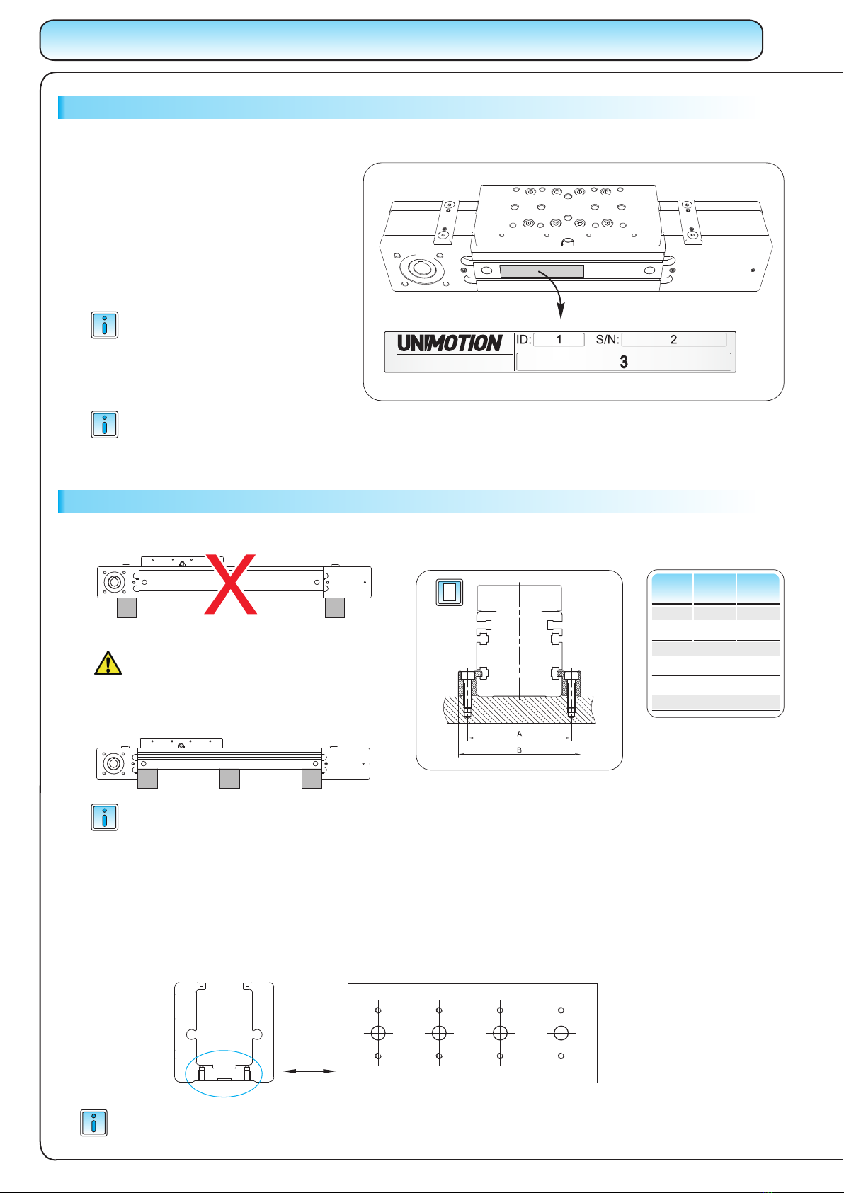
Lables and notices _ _ _ _ _ 1.010.0
Warranty _ _ _ _ _ 1.010.0
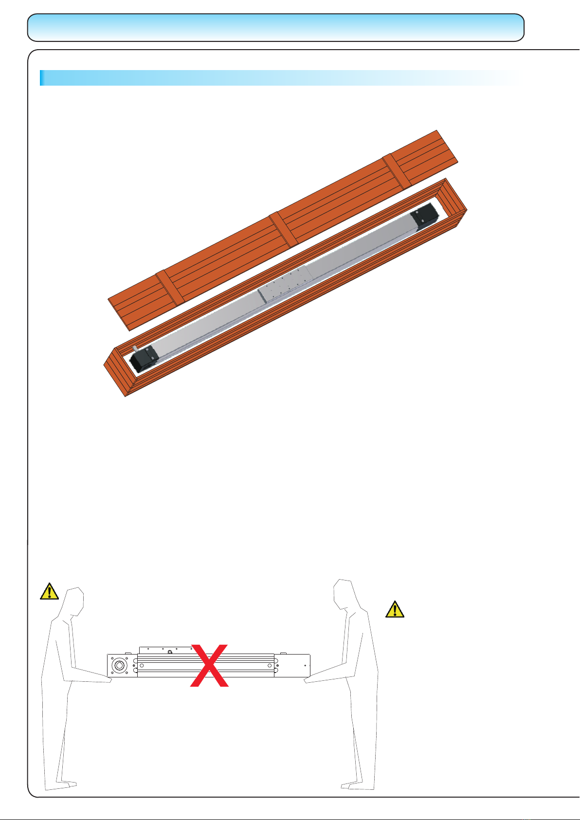
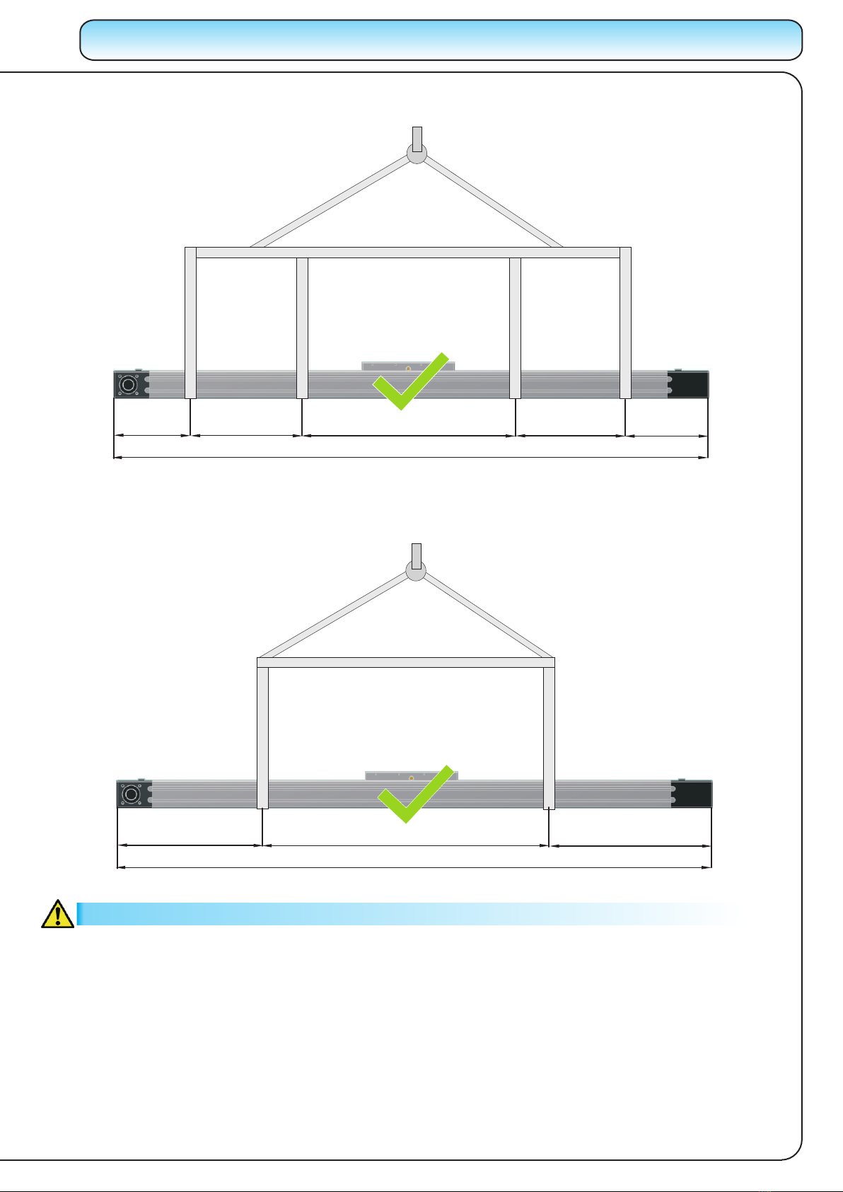
Handling the linear unit _ _ _ _ _ 1.015.0
Product description _ _ _ _ _ 1.025.0
Overview _ _ _ _ _ 1.035.0
MOUNTING _ _ _ _ _ 1.035.0
Fixing system _ _ _ _ _ 1.035.0
Magnetic field sensor _ _ _ _ _ 1.040.0
Mechanical and inductive switch_ _ _ _ _ 1.045.0
Motor with the coupling _ _ _ _ _ 1.050.0
MAINTENANCE _ _ _ _ _ 1.055.0
Lubrication of the carriage _ _ _ _ _ 1.055.0
Lubrication of the cover strip _ _ _ _ _ 1.055.0
Lubricant _ _ _ _ _ 1.055.0
Lubricant quantities and intervals_ _ _ _ _ 1.055.0
Normal operating conditions _ _ _ _ _ 1.060.0
ASSEMBLIES _ _ _ _ _ 1.065.0
MTJ 40 _ _ _ _ _ 1.065.0
MRJ 40 _ _ _ _ _ 1.070.0
MTJ 65 S _ _ _ _ _ 1.075.0
MTJ 65L _ _ _ _ _ 1.080.0
MRJ 65 L _ _ _ _ _ 1.085.0
MTJ 80 S _ _ _ _ _ 1.090.0
MTJ 80 L _ _ _ _ _ 1.095.0
MRJ 80 L _ _ _ _ _ 1.100.0
MTJ 110 S _ _ _ _ _ 1.105.0
MTJ 110 L _ _ _ _ _ 1.110.0
MRJ 110 L _ _ _ _ _ 1.115.0
MTJ ECO 40 S _ _ _ _ _ 1.120.0
MTJ ECO 40 L _ _ _ _ _ 1.125.0
REPLACEMENT OF ASSEMBLIES MTJ/MRJ SERIES _ _ 1.130.0
Removing the cover plate _ _ _ _ 1.130.0
Replacing the protection strip _ _ _ _ 1.130.0
Removing the end blocks _ _ _ _ 1.135.0
Replacing the toothed belt _ _ _ _ 1.135.0
Tensioning the toothed belt _ _ _ _ 1.140.0,
REPLACEMENT OF ASSEMBLIES MTJ 40 ECO SERIES _ 1.145.0
Loosening the toothed belt _ _ _ _ 1.145.0
Removing the end blocks _ _ _ _ 1.145.0
Replacing the toothed belt _ _ _ _ 1.150.0
Tensioning the toothed belt _ _ _ _ 1.150.0
Replacing the end blocks _ _ _ _ 1.155.0
Replacing the carriage _ _ _ _ 1.155.0
Replacing the profile / the rail _ _ _ _ 1.155.0
The specifications in order to improve the products in this catalogue are subject to change without notice.

MA
1.005.0
MTJ MRJ Series MANUAL
USED SYMBOLS
M2 M2,5 M3 M4 M5 M6 M8 M10 M12
0.4 0.7 1.3 2.8 5.6 9.6 23 45 74
8.8
Mmax
[ Nm ]
Remark, note
Warning!
For more information see the catalogue
Linear Units
Linear Units
Linear Units
Linear Units
Linear Units
Caution!
Keep Linear Unit clean!
Cover it, if necessary!
TIGHTENING TORQUES
The following tightening torques are recommended for screws of strength class 8.8
GENERAL SAFETY INSTURCTIONS
The linear unit must not be put into service until the final machinery into which it is installed has been
declared in confirmity with the provisions of the Machinery Directive, where appropriate.
Each operation of the Linear Unit that is not in compliance with its intended use can lead to the product being
damaged, accidents and at the same time stoppages in production. To ensure a safe operation please refer to this
Instruction Manual and the operating manual of other machinery where the Linear Unit is to be incorporated.
Linear unit satisfies the requirements of EC Machinery Directive 2006/42/EC according to European or
national standards of Safety of machinery:
·EN ISO12100-1
·EN ISO 12100-2
The linear units may only be installed, operated, maintaned, repaired or dismantled by appropriately qualified
personnel in accordance with the specification used in this manual use. All qualified personnel must have read and
understood this Instruction manual.
REGULATION OF USESAFE OPERATION
Requirements for personnel
Checking the linear unit
In accordance with the EU Health and Safety Directive 89/655/EEC article 4a, the operating company must
subject the unit to thorough checking prior to putting it into operation, after carrying out repairs, and after
malfunctions have occurred.
Danger!
Risk of coming into contact with power
conducting parts! Cut off power supply!
Screw
Tightening torque
To ensure the right functionality of the MTJ Linear Unit, it must be handled with care. It is not allowed to
put any tools or any other items which can cause damage to the linear unit on the linear unit.
The linear Unit must be proteceted against any liquid that can cause damage to it.
The MTJ Linear unit must be placed in a dry, clean environment. For information on conditions in which
the linear module can operate please contact us.
If the Linear Unit isn’t in use, place it in a dry, clean envrionment and cover it to prevent any damage.
GENERAL INFORMATION
Do not use glue in current step
Use dedicated tools for the current step
Use different tightening torque than in
the table on page 1.005.0
The specifications in order to improve the products in this catalogue are subject to change without notice.

MTJ MRJ Series
MANUAL
1.010.0
MODIFICATION OF THE LINEAR UNIT
The linear unit must not be modified without our written consent. Any such unauthorised modification will void our
liability in respect of the unit. The operating company may only carry out the maintenance and repair work detailed
in this Instruction manual.
WARRANTY
The warranty conditions are laid down in the terms and conditions of delivery and payment issued at the time of
the order. Warranty cover will be voided if:
·the unit is not operated in accordance with the stipulated regulation use;
·the instructions set out in this operating manual are not followed;
·the unit is modified without the consent of the manufacturers;
·the screws sealed by locking varnish are unlocked.
The manufacturer’s warranty in respect of maintenance and repair work applies only if original replacement parts
are used.
LABELS AND NOTICES
All notices and labels attached on the linear unit must be fully visible and are not allowed to be removed. They
must ensure compliance with all instructions contained on them. Damaged or illegible notices and labels must be
replaced.
The specifications in order to improve the products in this catalogue are subject to change without notice.

HANDLING THE LINEAR UNIT
The Linear units are carefully packed in a HARD WOODEN BOX for a safe transportation.
To take the Linear Unit out of the box, please consider the following handling instructions:
- Never lift the Linear Unit by the END BLOCKS - see PICTURE A
- Never grab by the TIMING BELT of the Linear Unit
- Never grab by the CARRIAGE
- Never grab by the PROTECTION STRIP
To take the Linear Unit out of the box, a suitable lifting tool is needed. Always lift and carry the Linear Unit by the
main profile.
The Linear Unit must be supported all the time during the handling until it is fixed - mounted on the place, where it is
meant to be. For correct handling please refer to page number 1.020.0
PICTURE A is showing, that handling with the Linear Unit in this position is wrong, because the profile, guides and
other components might get deflected or damaged.
PICTURE A
Carrying the Linear Unit
holding the END BLOCKS
isn’t allowed, it must be
carried holding the
PROFILE of the Linear Unit.
1.015.0
MTJ MRJ Series MANUAL
The specifications in order to improve the products in this catalogue are subject to change without notice.

2/7L3/7L2/7L
L
PICTURE C is showing correct handling of the Linear Unit.
PICTURE C
PICTURE B is showing correct handling of the Linear Unit.
PICTURE B
1/9L2/9L3/9L2/9L1/9L
L
WARNING
Calculate the weight of the linear unit in order to choose the suitable lifting tool for the transportation of the Linear
Unit.
Please refer to the catalogue UNIMOTION - LINEAR UNITS for weight calculations.
Linear Unit needs to be stored in dry place and protected against corrosion. Make sure that there is no danger for
the Linear Unit to get damaged.
MTJ MRJ Series
MANUAL
1.020.0
L > 2000mm
L < 2000mm
The specifications in order to improve the products in this catalogue are subject to change without notice.

PRODUCT DESCRIPTION
MTJ Series
1 - Drive block with pulley
2 - Corrosion-resistant protection strip (available also without protection strip)
3 - AT polyurethane toothed belt with steel tension cords.
4 - Carriage; with built in Magnets
5 - Aluminium profile-Hard anodized
6 - Linear Ball Guideway
7 - Central lubrication port; both sides
8 - Tension End with integrated belt tensioning system
1.025.0
MTJ MRJ Series MANUAL
MRJ Series
1 - Drive block with pulley
2 - Corrosion-resistant protection strip (available also without protection strip)
3 - AT polyurethane toothed belt with steel tension cords.
4 - Carriage; with build in Magnets
5 - Aluminium profile-Hard anodized
6 - Track Roller (journal Bearing)
Round guide )
8 - Central lubrication port; both sides
9 - Tension End with integrated belt tensioning system
7 - Two hardened steel (58/60 HRC
1
4
5
8
23
6
7
1
4
5
7
9
23
6
8
The specifications in order to improve the products in this catalogue are subject to change without notice.

MTJ MRJ Series
MANUAL
1.030.0
1
2
4
3
7
8
5
6
6
1 -
2 - AT polyurethane toothed belt with steel tension cords
3 - Carriage
4 - Linear Ball Guideway
5 -
6 -
7 -
8 -
Drive block with pulley
Belt Tensioning system
Lubrication port
Aluminium profile-Hard anodized
End block
MTJ ECO series
The specifications in order to improve the products in this catalogue are subject to change without notice.

Linear Units
Linear Units
Linear Units
Linear Units
Linear Units
Identification label and additional or replacement parts of the Linear Unit
1-ID number
2-Serial number
3 - Type of Linear Unit (ordering code)
In the case of ordering additional or
replacement parts for the Linear Unit
all data from the identification label
must be given.
Fixing system
±0,1
The linear Unit must be mounted by
the aluminium profile with evenly
distributed clamping fixtures along
the entire length!
www.unimotion.eu
The modules are mounted by
using fixtures which are placed
in the slot on the side of the
profile.
A
[ mm ]
B
[ mm ]
MTJ
MRJ
40
65
50
78
64,4
93
80
110
93
130
108
150
40 52 66
ECO
1.035.0
MTJ MRJ Series MANUAL
OVERVIEW
MOUNTING
The label must be fully visible(in particular details of the serial number) and must ensure compliance with all the
instructions contained on it. Damaged or illegible label must be replaced.
Fixing system - TAP/PIN Holes
Fixing the Linear Unit can also be done by the botom of profile using TAP / PIN holes, which can be made on request.
TAP / PIN holes can only be made based on the manufacturer’s drawing of the position and depth of
the TAP / PIN holes. For the drawings showing position and depth of TAP/PIN holes, please contact us.
Number of clamping fixtures:
Please refer to our catalogue UNIMOTION
Linear Units on page 7.000.0
The specifications in order to improve the products in this catalogue are subject to change without notice.

Magnetic field sensor - REED SWITCH
MTJ MRJ Series
MANUAL
1.040.0
MOUNTING
Magnetic field sensor
Tighten the screw
of the REED switch
with a torque of
MAX 0.6Nm
STEP 1: Placing of the switch can
be done on the left or right side of
the profile of the Linear Unit.
STEP 2: After the switch is placed
into the groove, tighten the screw.
STEP 1
STEP 2
The specifications in order to improve the products in this catalogue are subject to change without notice.

Mechanical switch with the bracket
Inductive switch with the bracket
1.045.0
MTJ MRJ Series MANUAL
MOUNTING
Mechanical and Inductive switch with the mounting bracket
Activation block STEP 1: Mount the activation block
on the connection plate in the desired
location. The activation block can be
mounted on the left or right side. After
the activation block is placed in the
desired location, tighten the screws.
STEP 2: Place either the mechanical
switch or inductive switch with
brackets in the slots and position
them on the desired location. The
mechanical or inductive switch with
brackets can be placed in the slots
either on the left or right side of the
profile of Linear Unit.
STEP 3: After the mechanical or
inductive switch with the bracket is
placed in the desired place in the
slots, tighten the screws of the
bracket.
For tightening torques for the screws please refer to page number 1.005.0
STEP 1
STEP 2
STEP 3
The specifications in order to improve the products in this catalogue are subject to change without notice.

Motor with coupling
MTJ MRJ Series
MANUAL
1.050.0
MOUNTING
For tightening torques for the screws please refer to page number 1.005.0
STEP 2
STEP 3
STEP 1
STEP 1
STEP 2
STEP 3
STEP 1
If motor adapter has inner through hole of the same size its entire length.
Attach one half of the coupling to the shaft of the linear unit and other to the shaft of the motor.
Insert coupling spider into one half of the coupling.
Attach motor adapter to the linear unit.
Attach motor to the motor adapter.
STEP 1:
STEP 2:
STEP 3:
The maximum torque and maximum
speed of the motor must never exceed the
limits of the Linear Unit!
Linear Units
Linear Units
Linear Units
Linear Units
Linear Units
If motor adapter has inner through hole with the narrowing at one end.
Attach motor adapter to the side on which the through hole is narower.
Attach complete coupling to the axle on the wider side of the hole.
Assemble two parts together and tighten the remaining screw on the coupling through appropriate hole in motor adapter.
STEP 1:
STEP 2:
STEP 3:
Tighten the screws on the coupling halves
with coupling tightening torque.
Linear Units
Linear Units
Linear Units
Linear Units
Linear Units
The specifications in order to improve the products in this catalogue are subject to change without notice.

Lubrication of the carriage
For each Linear Unit the basic lubrication is done in the factory before shipment.
All bearings have been lubricated for life and do not require any additional lubrication under normal operating
conditions.
Carriage lubrication is done via lubricating nipple
DIN 3405 D at the center of the carriage.
Recommended grease for MTJ
Lubcon TURMOGREASE LC 802 EP
Lubricant
For lubrication and re-lubrication of the linear units grease lubricant must only be used!
Do not use the grease which contains any solid parts!
The stated lubrication intervals in the table above are sufficient for the normal operating
conditions. If you have special operating conditions please contact us.
Lubrication intervals are every 500 operating hours or after the specified travel path
stated in the table above. Depends which value is first reached.
Lubricant quantities and intervals
Travel path
[ km ]
Travel path
[ km ]
Grease - relubricating quantity
[ cm ]
Carriage 2nd Carriage
Oil - relubricating quantity
[ cm ]
MTJ MRJ
65 65
5000 5000
0.4 6
80 80
110 110
5000 5000
10000 5000
0.7 8
1.4 12.5
40 5000 0.7
ECO
33
1.055.0
MTJ MRJ Series MANUAL
MAINTENANCE
Recommended oil for MRJ
Lubcon TURMOFLUID 4800
0.4
0.7
1.4
0.7
Recommended oil for the steel cover strip
Lubcon TURMOFLUID ED 13
Lubrication of the cover strip
Only applies for linear units with the steel cover strip!
Apply a thin oil film to the cover strip.
Once the oil is applied equally on the cover strip
move the carriage over the entire length.
Please note that, if the linear unit is working in an
area with many dust particles, the lubrication must
reapplied every once in a while.
The specifications in order to improve the products in this catalogue are subject to change without notice.

MTJ MRJ Series
MANUAL
1.060.0
MAINTENANCE
Normal operating conditions
Temperature:
Travel speed: MRJ
Load:
10 °C - 30 °C
= 10 m/s
MTJ ≤3 m/s
Stroke: MTJ MRJ 40 > 50 mm
MTJ MRJ 65, 80, 110 > 60 mm
=0.2 C
The specifications in order to improve the products in this catalogue are subject to change without notice.

1
2
3
4
5
6
7
8
9
10
11
12
1
1
1
1
1
1
1
2
2
DRIVE BLOCK MTJ / MRJ 40
TYPE 0
TYPE 1L
TYPE 1R
TYPE 2
TYPE 10L
TYPE 10R
TYPE 20
TENSION BLOCK MTJ / MRJ 40
CARRIAGE MTJ 40
PROFILE MTJ / MRJ 40
RAIL GUIDE MR 12 - M
TOOTHED BELT AT3 X 20 FOR MTJ / MRJ 40
PROTECTION STRIP FOR MTJ / MRJ 40
MAGNET FOR PROTECTION STRIP MTJ / MRJ 40
ALLEN SCREW M3 x 8 DIN 912
SQUARE NUT M3 DIN 562
COVER FOR Mr12
CARRIAGE BLOCK MINI MR12 MNZZ VS-N
36543
36644
36772
36645
53511
53513
53512
36541
36540
36591
8207
43239
41318
36932
52937
37303
-
41478
ITEM QTY PART NAME IDLENGTH / QTY
STROKE + 124
STROKE + 85
2 X STROKE + 425
STROKE + 165
STROKE + 124
(RAIL LENGTH/25)+0,5
482
11
31
5
910 6
7
12
1.065.0
MTJ MRJ Series MANUAL
ASSEMBLY MTJ 40
The specifications in order to improve the products in this catalogue are subject to change without notice.

1
2
3
4
5
6
7
8
1
1
1
1
2
1
1
2
DRIVE BLOCK MTJ / MRJ 40
TYPE 0
TYPE 1L
TYPE 1R
TYPE 2
TYPE 10L
TYPE 10R
TYPE 20
TENSION BLOCK MTJ / MRJ 40
CARRIAGE MRJ 40
PROFILE MTJ / MRJ 40
ROUND GUIDE FI 6
TOOTHED BELT AT3 X 20 FOR MTJ / MRJ 40
PROTECTION STRIP FOR MTJ / MRJ 40
MAGNET FOR PROTECTION STRIP MTJ / MRJ 40
36543
36644
36772
36645
53511
53513
53512
36541
36555
36591
13271
43239
41318
36932
ITEM QTY PART NAME IDLENGTH
STROKE + 124
STROKE + 85
2 X STROKE + 425
STROKE + 165
STROKE + 124
MTJ MRJ Series
MANUAL
1.070.0
ASSEMBLY MRJ 40
8
416
7 3 52
The specifications in order to improve the products in this catalogue are subject to change without notice.

1.075.0
MTJ MRJ Series MANUAL
ASSEMBLY MTJ 65 S
37 11 9 10 5 4 8 1 2 6
1
2
3
4
5
6
7
8
9
10
11
12
1
1
1
1
1
1
1
2
1
DRIVE BLOCK MTJ / MRJ 65
TYPE 0
TYPE 1L
TYPE 1R
TYPE 2
TYPE 10L
TYPE 10R
TYPE 20
TENSION BLOCK MTJ / MRJ 65
CARRIAGE MTJ 65 S
PROFILE MTJ / MRJ 65
RAIL GUIDE AR - HR 15
TOOTHED BELT AT5 X 32 FOR MTJ / MRJ 65
PROTECTION STRIP FOR MTJ / MRJ 65
MAGNET FOR PROTECTION STRIP MTJ / MRJ 65
SCREW DIN 912 M4 X 16
SLOT NUT 5 M4 FLAT
COVER FOR AR - HR 15
CARRIAGE BLOCK HRC15MN S V1 N
36615
37033
37039
37040
53568
53569
53570
36616
36617
36620
41518
41388
41317
36933
47079
5779
-
41509
ITEM QTY PART NAME IDLENGTH / QTY
STROKE + 180
STROKE + 140
2 X STROKE + 635
STROKE + 247
STROKE + 180
(RAIL LENGTH/60)+0,5
12
The specifications in order to improve the products in this catalogue are subject to change without notice.

MTJ MRJ Series
MANUAL
1.080.0
ASSEMBLY MTJ 65 L
7 3 11 9 10 5 4 8 1 2 6
1
2
3
4
5
6
7
8
9
10
11
12
1
1
1
1
1
1
1
2
2
DRIVE BLOCK MTJ / MRJ 65
TYPE 0
TYPE 1L
TYPE 1R
TYPE 2
TYPE 10L
TYPE 10R
TYPE 20
TENSION BLOCK MTJ / MRJ 65
CARRIAGE MTJ 65 L
PROFILE MTJ / MRJ 65
RAIL GUIDE AR - HR 15
TOOTHED BELT AT5 X 32 FOR MTJ / MRJ 65
PROTECTION STRIP FOR MTJ / MRJ 65
MAGNET FOR PROTECTION STRIP MTJ / MRJ 65
SCREW DIN 912 M4 X 16
SLOT NUT 5 M4 FLAT
COVER FOR AR - HR 15
CARRIAGE BLOCK HRC15MN S V1 N
36615
37033
37039
37040
53568
53569
53570
36616
36618
36620
41518
41388
41317
36933
47079
5779
-
41509
ITEM QTY PART NAME IDLENGTH / QTY
STROKE + 230
STROKE + 190
2 X STROKE + 685
STROKE + 297
STROKE + 230
(RAIL LENGTH/60)+0,5
12
The specifications in order to improve the products in this catalogue are subject to change without notice.

1.085.0
MTJ MRJ Series MANUAL
4
5
3
716
82
1
2
3
4
5
6
7
8
1
1
1
1
2
1
1
2
DRIVE BLOCK MTJ / MRJ 65
TYPE 0
TYPE 1 - L
TYPE 1 - R
TYPE 2
TYPE 10 - L
TYPE 10 - R
TYPE 20
TENSION BLOCK MTJ / MRJ 65
CARRIAGE MRJ 65
PROFILE MTJ / MRJ 65
ROUND GUIDE FI 6
TOOTHED BELT AT5 X 32 FOR MTJ / MRJ 65
PROTECTION STRIP FOR MTJ / MRJ 65
MAGNET FOR PROTECTION STRIP MTJ / MRJ 65
36615
37033
37039
37040
53568
53569
53570
36616
36619
36620
13271
41388
36931
36933
ITEM QTY PART NAME IDLENGTH
STROKE + 230
STROKE + 190
2 X STROKE + 685
STROKE + 297
STROKE + 230
ASSEMBLY MRJ 65 L
The specifications in order to improve the products in this catalogue are subject to change without notice.
This manual suits for next models
14
Table of contents