10 11
Alterations which serve the technological progress as well as errors excepted! ORIGINAL MANUAL NORSUPWWW.NORSUP.EU Alterations which serve the technological progress as well as errors excepted!
SALT CHLORINATORSALT CHLORINATOR
EN
ES
FR
IT
DE
PT
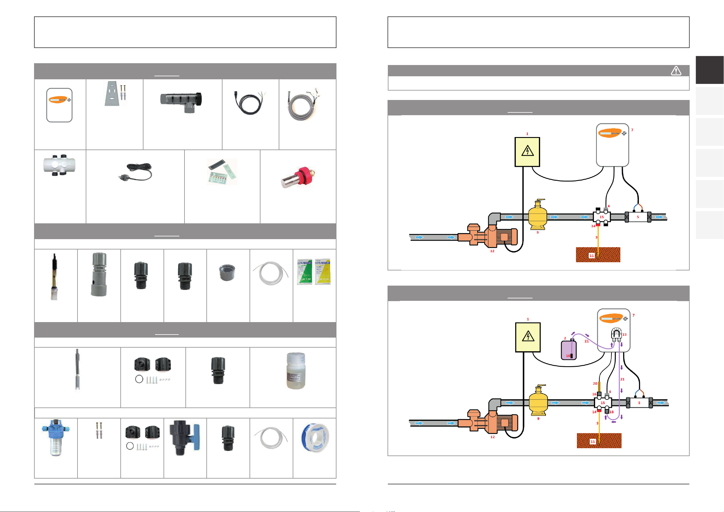
PRO model
with the optional measuring kit:
1: Electrical power supply (not provided)
2: pH corrector container (not provided)
3: Copper cable (not provided)
4: Salt/temperature/low-water sensor
5: In-line cell
5-A: Alternative assembly for T-cell
6: Measuring chamber
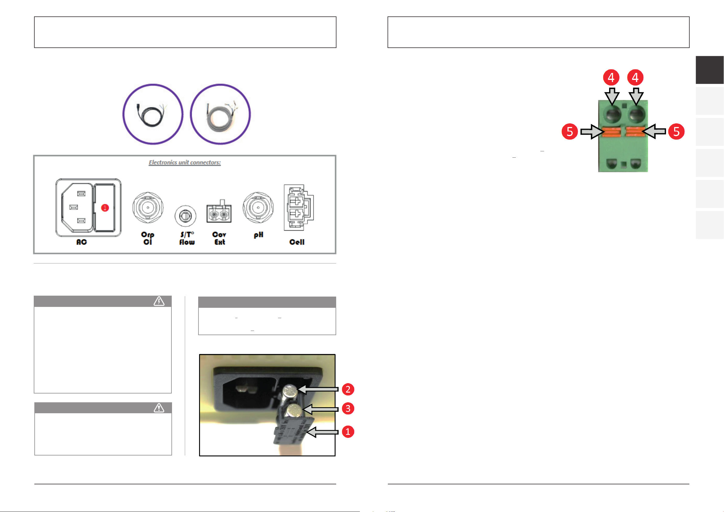
7: Electronics unit
8: Saddle clamp
9: Filter (not supplied)
10: Filter with ballast
11: Ground rod (not provided)
12: Filtration pump (not provided)
13: Peristaltic pump
14: Pool Ground (optional)
15: Accessories holder
16: Probe connector
17-A: Fitting
17-B: Fitting
18: Injection connector
19: ORP probe
20: pH probe
21: Semi-flexible tubing
22: Valve
7. INSTALLATION
7.1. IMPORTANT PRELIMINARY PRECAUTIONS
• The treatment capacity of the equipment must be
appropriate for the volume of the pool to be treated,
the number of people using the pool, the presence
of nearby equipment (overflow, reflecting pool, slide,
etc.) and the weather conditions where the equipment
is installed.
• Use water from the mains water supply. Do not use
water of natural origin (rainwater, run-off, ponds,
lakes or boreholes), as this may cause premature
deterioration of the electrolytic cell. • Do not use any
anti-algae products containing copper or other
metals, as this may cause premature deterioration of
the electrolytic cell.
• Check that the filtration pump and filter are in good
condition and working correctly. Also check the flow
rate of the filtration pump, the capacity of the filter, and
the outer diameter of pipework (either 50 or 63 mm).
• The equipment must be installed in a closed, dry and
sufficiently ventilated room which is protected from
water sprays and UV rays. The temperature inside
this room must not exceed 40°C.
→ If these premises are located in a country with a hot
and humid climate, they must be air conditioned.
→ If these premises are located in a country with a
temperate climate, they must be equipped with
forced ventilation.
• Determine where exactly each component will be
positioned, taking into account its size and the length
of its power cables. Also anticipate extra space around
the equipment, in order to facilitate access for
maintenance.
• The pH corrector drum must be installed a safe
distance away from any electrical device or any other
chemicals. Failure to follow these instructions may
lead to abnormal oxidation of the metal parts,
possibly resulting in complete device failure.
• Be very careful to ensure that the various components
are correctly positioned in relation to each other in
accordance with the fluid direction, as indicated in the
installation diagram. Install the cell and accessories
holder in a horizontal position first, then all other
devices for water treatment, cleaning or heating
(just before flow out into the pool). To protect property
and people, the cell and accessories holder must be
installed in series (and not in parallel), and the cell
must be positioned just after the accessories holder.
If constraints concerning the filtration heat contactor
make it necessary to install components in a way
that differs from the installation diagram, ensure
that this assembly is approved by a professional. You
must also install the flow sensor (see the overview of
the “Sensor settings” menu in chapter 11). The same
applies when intentionally deciding to install
components in a different way, for example in
order to position the cell and accessories holder
in a bypass configuration.
• A sufficient flow of water must be maintained in
the cell when connected to a power supply. If the
filtration pump has a variable flow, you must install
a flow sensor so that electrolysis automatically stops
when flow is insufficient. The electronics unit is fitted
with a socket to connect a flow sensor. Enable the
flow sensor function (see the description of the
„Sensor Parameters“ menu in chapter 11).
• All probes must be installed vertically and on the
level (not tilted) to ensure proper operation.
• The water pressure in the cell must not exceed 3 bar.
All hydraulic components installed must be able to
tolerate water pressures likely to be encountered as
part of normal use. There should be no leakage from
any part, including pipework.
7.2. MOUNTING THE ELECTRONICS UNIT
ONTO A WALL
1) Attach the wall mount to the wall using the screws
and plastic anchors provided, following the diagrams
below:
2) Slide the electronics unit downwards onto the wall
mount.
ATTENTION
Before installing the equipment, the following
instructions must be followed:
FRONT VIEW SIDE VIEW