Nortek AOS User manual


Introduction 3
© 2018 Nortek
Introduction
1
Congratulations with your new Nortek AOS Buoy!
Nortek AOS Buoy is a flexible, battery operated and complete system which offers online
access to currents, oxygen and/or salinity data from virtually any location worldwide. Data is
communicated from the connected sensors to a communication device (named AOS tube)
and an iridium satellite modem communicates the data to a server. The serves saves your
AOS data, and through a cloud hosted web application (www.aos.nortek.no), you will always
find your updated real time data. The Nortek AOS Buoy is built to withstand rough treatment
and includes a radar reflector. In addition there is an option to install a blinking signal light.
This manual contains a mounting manual and other useful information. If there are any
uncertainties, we recommend sending an email for guidance. In addition, please contact us
if you find any information missing. We appreciate your feedback, and other users will too!
Contact information:
Email: inquiry@nortekgroup.com (general email) or [email protected] for technical
question.
Adress:
Nortek AS
Vangkroken 2
1351 Rud
Norway

Nortek Sensor Buoy4
© 2018 Nortek
Technical specifications
2
Weight and dimensions
Weight
~40kg
Diameter
400mm
Length
2500mm
Sensor contacts
1*8-pin (Aquadopp Profiler) and optional
1*5/6-pin (oxygen-/salinity sensor)
Power
Batteries
6 * 100 Wh alkaline batteries (Nortek)
Environment
Operating temperature
- 20°C til + 45°C
Data communications
Data transfer
Iridium
Current measurements
Nortek Aquadopp Profiler. Further details in
data sheets.
Aquadopp Profiler 400 kHz
(http://www.nortekgroup.com/products/
aquadopp-profiler-400-khz)
Aquadopp Profiler Z-Cell 600 kHz
(http://www.nortekgroup.com/products/
aquadopp-z-cell-600-khz)
Aquadopp Profiler 2 MHz
(http://www.nortekgroup.com/products/
aquadopp-profiler-2-MHz)
Oxygen sensor
Manufacturer:
Insite IG, Dissolved Oxygen Model 31
Measurement parameters:
Oxygen and temperature
Sensor technology:
Optical
Maximum depth:
50 meter
Measurement range:
0-25 ppm
Precision:
1% of reading or 0.02ppm
Resolution:
0.01ppm of reading, < 4ppm
0.1ppm of reading, > 4ppm
Salinity sensor
Manufacturer:
Ponsel Measure, CTZN
Measurement parameters:
Salinity (conductivity) and temperature
Maximal depth:
50 meter
Measurement area, conductivity:
Measurement interval:
0-100 mS/cm
0-70 ppt
Resolution:
0,01 mS/cm
Measurement, salinity:
5-60g/kg
Resolution:
0,01 g/kg
Blinking light
Manufacturer:
Jotron AS, Tron ML-300
System:
LED (yellow)
Activation switch:
ON/OFF daylight sensor
Light intensity:
5 Cd
Blinking interval:
0.5 sec OFF/ 2.5 sec ON. 20 blink/min
Data presentation
Internet: www.aos.nortek.no

Included in the delivery 5
© 2018 Nortek
Included in the delivery
3
1. SPARBUOY-250
2. 6*100 Wh batteries and a battery tube
3. Shackle for chain mounting
4. Oxygen- or salinity sensor + clamp + 5/6-pin cable (if ordered)
5. Aquadopp Profiler + clamp
6. AOS tube + clamp
7. Blinking light (if ordered)
In addition to the main components, the following is included:
2-pin/2-pin cable from AOS tube to battery tube
8-pin/8-pin cable from Aquadopp Profiler to battery tube
2-pin cable from battery tube to blinking light (if ordered)
Screws kit
Dummy plug

Nortek Sensor Buoy6
© 2018 Nortek
Function description
4
More details about sensors and current measurements are available on Nortek's website (
www.nortekgroup.com), but the summary below may be useful:
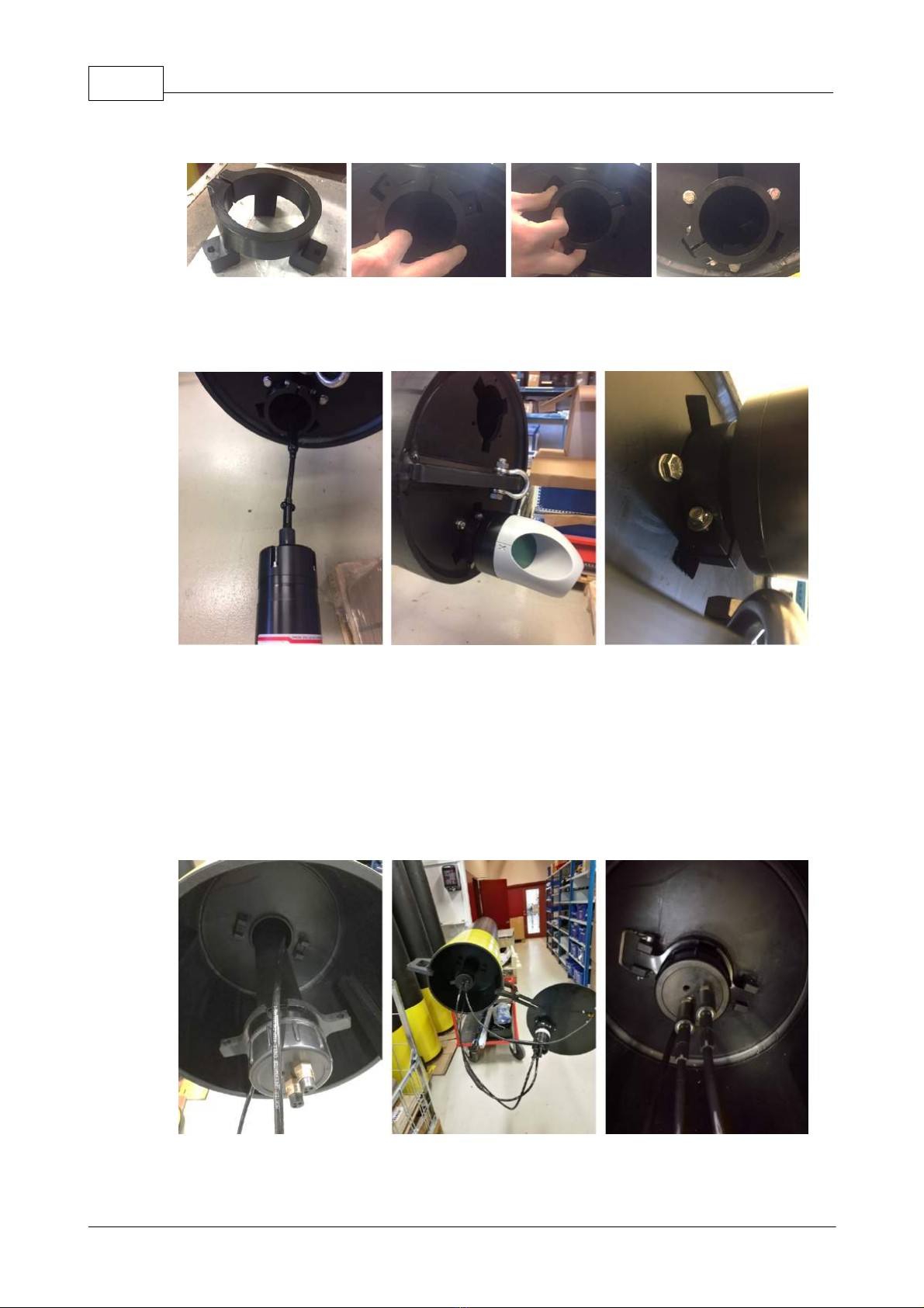
Current profiler: To start sampling, simply connect the instrument to the batteries. The
current profiler is configured to measure current speed and direction every 10.minutes, at
three depths: 5 m, 10 m and 15 m (if other is not specified).
Battery tube: Contains 6 * 100 Wh alkaline (not rechargeable) batteries. The batteries are
connected to the battery tube when shipped from Nortek. In other words, there is no need to
connect the batteries to the battery tube first time the AOS buoy is deployed.
The oxygen sensor is an optical sensor that measures percent dissolved oxygen (%
saturation), based on a method called fluorescence. The sensor sends out energy as light,
with very specific wave length (color) that goes through a material that fluoresces. Outside
the fluorescent material there is a membrane that keeps out the water, while letting in
oxygen molecules. The number of oxygen molecules is therefore in equilibrium with the
number of oxygen molecules in the water outside. When the fluorescent light hits an oxygen
molecule, the energy in the light decreases without the wavelength (color) changing.
Oxygen also causes the energy in the light to be absorbed. If there is dissolved oxygen in
the water, the returned light will have reduced energy, and this energy decrease is
proportional to oxygen content.
The salinity / conductivity sensor. Conductivity is the waters ability to conduct an electric
current, and is indicated by the unit mS / cm (milli siemens). Salinity is a measure of salt
content in a given amount of water, and is stated in g / kg (ppt). The sensor measures the
conductivity by generating an electric field in the water using a coil, then measuring this
electric field using another coil. The current measured by coil number two is proportional to
conductivity in the water. Higher salinity leads to higher electrical conductivity. Conductivity
increases at increasing temperature, therefore, the temperature is also measured. Salinity is
calculated using oceanographic tables and standard equations.
The internet webpage indicates the battery status. It is recommended to change batteries
when the indicator turns red. The procedure for change of batteries is described in chapter
8.

Function description 7
© 2018 Nortek
Mounting Nortek AOS buoy
5
We recommend to test the system before deployment. Make sure data from the current
profiler and oxygen/salinity is displayed in www.aos.nortek.no.
We recommend to mount the AOS buoy as described in the instructions below:
1: Open the top cover of the buoy. Mount the blinking light on the top cover with the four
supplied screws (as picture 1a illustrates).
Picture 1: a) Blinking light mounting, b) AOS tube mounting, c) Output AOS tube
2: To mount the AOS tube on the top cover of the buoy: First mount the clamp in the
available hole in the top cover, and thread the tube halfway through the cover (1b). The
antenna on the AOS tube should point in the same direction as the blinking light. Tighten the
screws on the clamp and make sure the tube is fastened and is stuck.
3: The AOS tube has three outputs (picture 1c). One 8-pin for the Aquadopp profiler, a 2-pin
for the battery cable and a 5-pin for the optional oxygen/salinity sensor. If the 5-pin output is
not in use, protect the output with a dummy plug.
4: Pull the 8-pin cable from the AOS tube through the AOS buoy (2a). If using an additional
sensor, pull the 5/6-pin through the buoy. Note: It is important to do this step before
mounting the battery tube.
Picture 2: Pull the cable(s) through the buoy. a) seen from top of buoy: cable
pulled through buoy. b) seen from bottom of buoy: cable pulled through buoy.

Nortek Sensor Buoy8
© 2018 Nortek
5: Fasten the clamp for the Aquadopp Profiler in the bottom of the buoy. If using an oxygen/
salinity sensor, fasten the related clamp to the bottom of the buoy as well.
Picture 3: a) Clamp for Aquadopp Profiler. b) Place the bracket in the slot. c) Adjust and align the clamp
with the holes in buoy. d) Use the supplied screws for fastening
6: Connect the 8-pin cable to the Aquadopp Profiler (4a). If using an oxygen sensor, connect
the 5/6-pin cable to the sensor.
Picture 4: a) Connector between Aquadopp Profiler and cable. b) Push Aquadopp Profiler through the
clamp. c) Tighten the screws.
7: Push the Aquadopp Profiler as far as possible into the buoy through the clamp. If it is not
possible to push the instrument as far as picture 4b illustrates, please contact Nortek for a
solution.
Note: Rotate the head so the transducers looks away from the shackle and mooring
rope.
8: Tighten the clamp screws for the Aquadopp Profiler. Do the same procedure for oxygen/
salinity sensor.
9: From the top of the buoy, thread the battery tube in place. There is an indent in the
battery tube collar for the cables (5).
Picture 5: a) Place the cables in the indent of the battery tube collar. b) Mount the cable from the AOS tube
and the cable from the blinking light to the battery tube. c) Use the supplied locking splints to fasten the

Mounting Nortek AOS buoy 9
© 2018 Nortek
10: Fasten 2-pin cable from the AOS tube to the battery tube (5b). Fasten the 2-pin cable
from the blinking light to the battery tube.
11: Use two of the supplied locking splints to fasten the battery tube to the inside of the
buoy.
12: Fasten the top cover to the buoy and lock with supplied locking splint.
13: The Nortek AOS buoy is ready for deployment. Use the supplied shackle to fasten the
chains and mooring rope to the bottom of the buoy before deployment.

Nortek Sensor Buoy10
© 2018 Nortek
Deployment and mooring
6
Nortek AOS buoy can be mounted at great depths and in strong currents. We have
modeled and collected data based on tests of the hydrodynamic behavior during typical
current environments. The table with the data collected (see below) can be used as a
guidance for deployment. Please don't hesitate to contact Nortek for assistance.
A typical buoy-mooring is presented in figure 1. Subsurface buoys is installed at 30 meter
depth if necessary.
Note: Make sure that the current profiler transducers point away from any mooring rope as it
will cause disturbance in the data.
Mooring. Lengths/weights are just examples. See
table below for more details.
Standards:
Mooring rope:
8 mm dyneema rope
Length of rope below buoy:
10 m
Mooring weight in water column:
10 m chain, 80 kg
Length of top rope:
See table below
Sub-surface buoy:
14’’ Nokalon buoy
Bottom rope:
Depends on total depth. See table below
Mooring weight, anchor:
See table below
Note: In the following tables it is assumed a maximum current of 1 m/s in shallow water.
"Length of top rope" needs to be adjusted if a location is exposed of stronger currents than
this.
In deep water, the data is presented as functions of the number of subsurface buoys.
Subsurface buoys are an important parameter when it comes to hydrodynamic behavior in
deep water.
The percentage of used buoyancy is always <70% in the tables below. This is to be sure
that the AOS buoy is not fully submerged underwater in the high current speed.

Deployment and mooring 11
© 2018 Nortek
Shallow water (40-100 m). Number of subsurface buoys is 0.
Water depth
Assumed
maximum current
speed
Rope length, top
rope
Mooring weight,
anchor
Maximum
horizontal
displacement
< 40 m
1 m/s
5 m
150 kg
18 m
40 m
1 m/s
5 m
150 kg
18 m
60 m
1 m/s
10 m
200 kg
35 m
80 m
1 m/s
20 m
200 kg
55 m
100 m
1 m/s
20 m
250 kg
60 m
Deep water (100-500 m).
Water depth
Total subsurface
buoys
Rope length, top
rope
Mooring weight,
anchor
Maximum
horizontal
displacement
100 m
2
5 m
200 kg
30 m
200 m
2
10 m
300 kg
60 m
250 m
4
10 m
300 kg
65-70 m
300 m
4
15 m
350 kg
80-90 m
400 m
6
20 m
450 kg
125 m
500 m
8
20 m
600 kg
140 m

Nortek Sensor Buoy12
© 2018 Nortek
Setup webpage
7
Note the stationID for the AOS tube. The 4-digit number is the final test documentation and
it is written on the AOS tube.
Log in to www.aos.nortek.no with username and password and access the data after the
Nortek AOS buoy is deployed. Available functions at www.aos.nortek.no:
Key parameters
Customizable graphic display
Historical data
Option to download data to Excel
Map

Setup webpage 13
© 2018 Nortek
Change batteries
8
1: To access the batteries and battery tube open the top cover on the buoy. Pull out the
battery tube (picture 1a).
2: Unscrew the battery tube collar. Loosen the molex-contact between battery tube collar
and the batteries. (Picture 1a-1b).
3: Take out the whole battery rail and observe how the batteries are mounted before
removal. Replace with 6 new batteries and place the battery rail careful into the battery tube
again.
4: Connect the 2-pin molex-contact to the battery tube collar again (1d).
5: Tighten the battery tube collar. Tip: Avoid twisting the internal cables: first, rotate battery
tube cover 5 revolutions counter-clockwise. Second, put the collar on the battery tube and
rotate clockwise until collar is full tightened (1e).
6: Place the battery tube back into the buoy, and make sure the cables for the current
profiler (and sensor) are placed in the indent of the battery tube collar.
7: Fasten both of the 2-pin cables on the top of the battery tube collar.
8: Shut the top cover of the buoy and fasten with locking splint. As a confirmation of a
successful battery change, check if the blinking light is blinking.
Picture 1 a) Open top cover and drag out battery tube. b) loosen the white molex-connector. c) Take out
the battery rail. Note the placement of the batteries. Replace with new batteries d) Connect the
molex-contact. e) tighten the battery cover.
We recommend to have a spare battery tube available, in that way, the battery tube is the
only component to change in the field. This is to avoid changing exposed batteries in field
environments.

Nortek Sensor Buoy14
© 2018 Nortek
Maintenance
9
Maintenance:
Recommended maintenance interval of the buoy is every third month. Check for bio fouling,
mounting of mooring and mounting of instrument/sensor.
Oxygen sensor: Bio fouling on oxygen sensor will affect the measurement. This usually
leads to a decrease of the average oxygen level and/or unnaturally large variations between
daytime and nightly measurements. This phenomenon will typically be more prominent in
the summer, and we therefore recommend to pay extra attention in this period with regard
to visual inspection and cleaning of the sensors.
Simply clean the sensor by washing gently with soapy water and a soft sponge, cloth or
brush (for example a toothbrush).
Important! Do not use sharp tools. This can cause irreparable damage to the sensor.
Salinity Sensor: Clean the sensor with soapy water and make sure the sensor hole is not
clogged.
Current profiler: For maintenance of the current profiler, the Service Chapter (Chapter 1) of
the Nortek Comprehensive Manual is recommended and available for download here: http://
www.nortekgroup.com/manuals-quick-guides
Maintenance interval: For oxygen and salinity, it is recommended to check the sensors once
a week, especially if there is little experience with the level of bio fouling. Geographical
differences and seasonal differences must also be included in the assessment. Our
experience for the current profiler is that monthly checks are often enough. Again, location
and season must be considered.
Transportation: When transporting a Nortek AOS buoy, you may want to disassemble the
instrument if you can not secure it properly. To do this, unscrew the two screws on the
clamp for the current profiler (see picture below). Pull out the instrument and disconnect the
underwater cable that goes to the communication device at the top of the buoy.
Calibration:
Oxygen Sensor: If the oxygen sensor(s) shows unnatural or unstable values, it may be a
sign that recalibration is required. A simple test can be done before contacting Nortek: Test
the sensor in a saturated solution. For example, use a bucket of tap water. Note that water
from the tap will typically be over-saturated, so wait for approx. 30 minutes before the
measurements are taken. Contact Nortek if the oxygen sensor is outside +/- 5% of the
100% saturated solution.

Maintenance 15
© 2018 Nortek
Salinity Sensor: The salinity sensor cannot be calibrated.
The current profiler cannot be recalibrated. Contact Nortek if it is suspected that the
instrument is not measuring correctly, and Nortek can perform a service/verification.
Storage:
The sensors and the instruments must be stored with care and protected against careless
relocation/handling. Sensors should not be stored in cold environments, due to calibration
purposes. If the system is stored over a long period of time, it can be disabled for a period of
time to save costs. Please contact Nortek for more information.

Nortek Sensor Buoy16
© 2018 Nortek
Service and repair
10
receive an RMA number. This is a mandatory reference number that contributes to fast and
trouble-free handling.
Information that MUST follow the shipment:
RMA Number
StationID
Company Name
Contact person
Delivery Address
Invoice address
Telephone
Email
Important! Freight insurance in connection with repairs is not covered by Nortek. Make sure
the equipment is adequately insured before shipping.
Please note that sensors exposed to severe mechanical stress (vibration/shock), may
reduce target accuracy significantly and may be destroyed if they are not properly
packaged. Nortek is not responsible for direct costs or costs of consequential damages
associated with equipment being lost or destroyed during transport.
Nortek insures shipment back to customer and bills this together with repair/shipping. In
case of warranty repair, transport and freight insurance to Nortek's customer is covered.

Service and repair 17
© 2018 Nortek
Table of contents