Step 1: Remove the stand cover. Pull upward on the center catch (see Figure 4) and
remove the stand cover from the stand base. The cable routing tracks are now accessible in
the stand base (see Figure 5).
Step 2: Connect the AC power adapter (optional). Connect the AC power adapter (not
supplied) to the AC adapter jack in the bottom of the phone (see Figure 2). Form a small
bend in the cable and thread the adapter cord through the channel in the stand base. Plug
the AC power adapter into the nearest AC power outlet.
Note: Your IP Phone 1110 supports both AC power and Power over Ethernet (PoE),
including IEEE 802.3af standard power. To use AC power, use only the Nortel-approved AC
power adapter (RoHS Global Power Supply, PEC #: N0089601), which can be ordered
separately. To use Power over Ethernet (PoE) power, your connected LAN must support
PoE; an AC power adapter is not required.
Step 3: Install the handset. Plug the end of the handset cord with the short straight section
into the handset. Plug the end of the handset cord with the long straight section into the
handset jack in the back of the phone (see Figure 2) marked with the symbol +. Form a
small bend in the cord, and then thread it through the channel in the stand base marked with
the symbol +so that it exits in the handset cord channel on the right -hand side of the stand
base (see Figure 4).
Step 4: Install the LAN Ethernet cable. Plug one end of the supplied LAN Ethernet cable
into the LAN Ethernet port on the back of your phone (see Figure 2) marked with the symbol
%, and thread the cable through the channel in the stand base marked with the symbol %.
Connect the other end of the cable to your LAN Ethernet connection.
Step 5: Install the PC Ethernet cable (optional). If you are connecting your PC Ethernet
through the phone, plug one end of the PC Ethernet cable (not supplied) into the PC
Ethernet port on the back of your phone (see Figure 2) marked with the symbol (, and
thread the cable through the channel in the stand base marked with the symbol (. Plug the
other end into the LAN port on the back of your PC..
Step 6: Wall-mount your phone (optional). Your IP Phone 1110 can be mounted either by:
(Method A) using the mounting holes on the bottom of the phone stand, or (Method B) using
a traditional-style wall-mount box with RJ-45 connector and 15-cm (6-inch) CAT-5 cable (not
supplied).
Complete steps 1-5, as needed, before you wall-mount your phone:
Method A: Using the stand cover (part removed in step 1), mark the wall-mount holes by
pressing the bottom of the stand cover firmly against the wall in the location where you wish
to install the phone. Four small pins on the bottom of the stand cover make marks on the
wall. Use the marks as a guideline for installing the wall-mount screws (not supplied). Install
the screws so that they protrude 3 mm (1/8 inch) from the wall, and then position the phone
stand mounting holes (as shown in Figure 5, Method A) over the screw heads. You may
need to remove the phone from the wall to adjust the lower screws. When the lower screws
fit snugly, tighten the top screws.
Method B: Attach the 15-cm (6-inch) CAT5 cable (not supplied), position the phone stand
mounting holes (shown in Figure 5, Method B) over the mounting rivets, push the phone
onto the rivets, and down to lock into position.
Step 7: Replace the stand cover. Ensure that all cables are neatly routed and press the
stand cover into place until you hear an audible click.
Step 8: Put the phone in the wall-mount position. If you wall-mounted your phone, put it
in the wall-mount position by pressing the tilt lever and pushing the phone towards the stand
until nearly parallel with the stand. Release the tilt lever and continue to gently press the
phone towards the stand until you hear an audible click (from the wall mount lever). Ensure
the phone is securely locked in position.
IP Phone 1110 installation
Caution: Your IP Phone 1110 is shipped with the stand locked in position. To release
the phone from the stand, press the wall-mount lever (see Figure 3) and gently tilt the
phone up from the stand a little. When you’re sure the phone is released from the
stand, press the tilt lever and tilt the phone up from the stand all the way.
Figure 3
Release the phone from the stand.
Wall-mount
lever
Tilt lever
Wall-mount lever
Figure 4
Remove the stand cover.
Tilt Lever
Button
Center
Catch
Handset
cord channel
IP Phone 1110 installation
Figure 5
Cable routing tracks
Method A
Method B
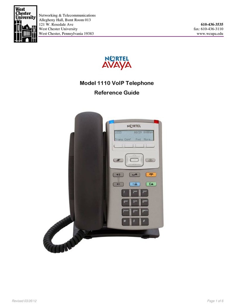
IP Phone 1110 controls:
Controlling volume
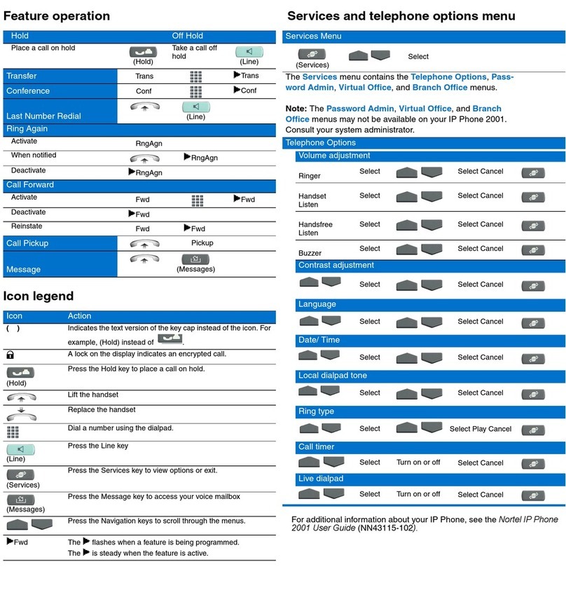
Press the up or down volume control key while using your handset or speaker to adjust the
volume of the associated device.
Answering a call
Lift the handset to answer a ringing call.
Making a call with the handset
Lift the handset and enter the phone number on the dialpad. When your call is complete,
press the Goodbye key or return the handset to the cradle.
Making a call using on-hook dialing
Press the Line key and enter the phone number on the dialpad. When your call is
answered, lift the handset. When your call is complete, press the Goodbye key or return
the handset to the cradle.
Placing a call on Hold
While on a call, press the Hold key to place your caller on hold. To retrieve your caller on
hold, press the Line key.
Setting the contrast
To adjust the display contrast, press the Services key, select Telephone Options, and
select Contrast Adjustment. Use the up/down arrow keys or up/down soft keys to change
the setting.
Setting the language
To select the language used by the local menus, press the Services key twice quickly to
open the local menu. Select 1. Preferences, select 2. Language, and use the up/down
arrow keys to choose the language.
Note: Use the Telephone Options menu to select the language used by server-based
features. Consult the IP Phone 1110 User Guide for more information.
IP Phone 1110 installation and controls


