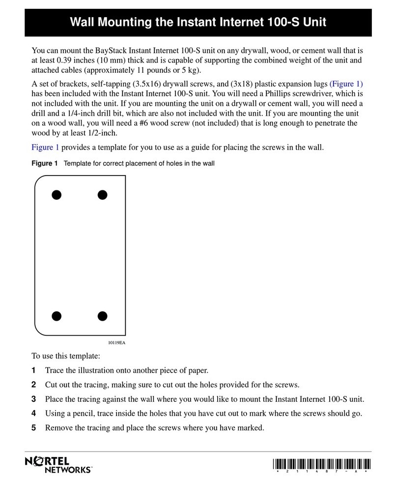
Nortel AccessNode 2016 User manual
Other Nortel Network Hardware manuals
Nortel
Nortel BayStack 650 Manual
Nortel
Nortel Meridian 1 Option 11C Technical manual
Nortel
Nortel BayStack 100 Series User instructions
Nortel
Nortel HomeOffice II User manual

Nortel
Nortel 2230l 2231 User manual
Nortel
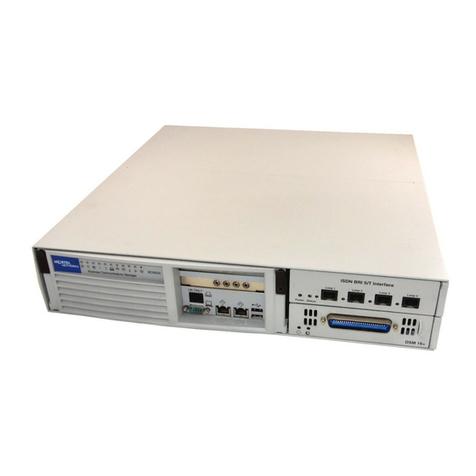
Nortel BCM200 Product manual

Nortel
Nortel BayStack 600 Series Instruction Manual

Nortel
Nortel 2340 User manual

Nortel
Nortel 1800 Instruction Manual
Nortel
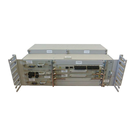
Nortel Optical Multiservice Edge 6130 Technical manual

Nortel
Nortel 1001t User manual
Nortel
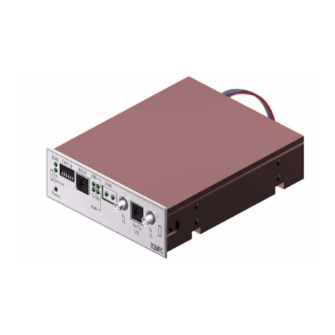
Nortel R2MFC Operator's manual
Nortel
Nortel C251 User manual
Nortel
Nortel SONET AccessNode User manual
Nortel
Nortel IVR 2.5/S User manual
Nortel
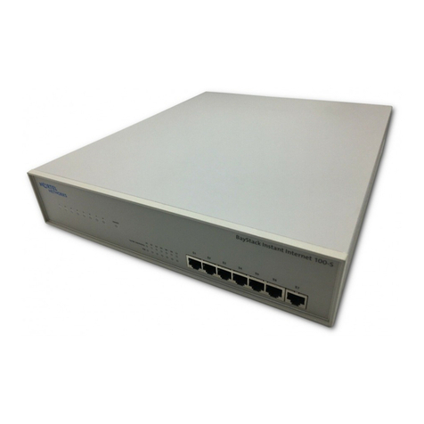
Nortel BayStack 100-S User manual
Nortel
Nortel Meridian 1 Option 11C Installation and operation manual
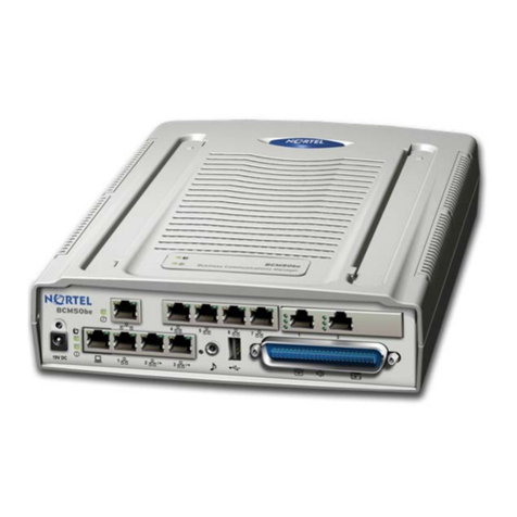
Nortel
Nortel BCM50 2.0 User manual

Nortel
Nortel BayStack 100-S Instruction Manual

Nortel
Nortel NAC User manual
Popular Network Hardware manuals by other brands

Matrix Switch Corporation
Matrix Switch Corporation MSC-HD161DEL product manual

B&B Electronics
B&B Electronics ZXT9-IO-222R2 product manual

Yudor
Yudor YDS-16 user manual

D-Link
D-Link ShareCenter DNS-320L datasheet

Samsung
Samsung ES1642dc Hardware user manual

Honeywell Home
Honeywell Home LTEM-PV Installation and setup guide
