North Atlantic SRS 5330A User manual
5330A Operations Manual
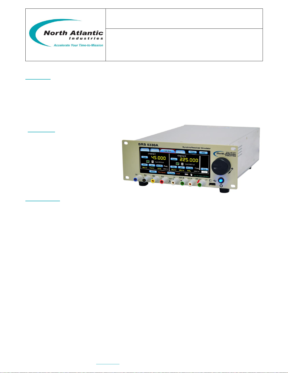
SYNCHRO/RESOLVER SIMULATOR
TWO SYNCHRO/RESOLVER OUTPUTS (UP TO 6 VA)
PLUS OPTIONAL 6 VA REFERENCE SUPPLY
North Atlantic Industries, Inc.
631.567.1100 / 631.567.1823 (fax)
6/12/2018
5330A Operations Manual Rev A6
110 Wilbur Place, Bohemia, NY 11716
www.naii.com
Cage Code: 0VGU1
Page 1 of 24
GENERAL
This Operations Manual contains a general description, specifications, installation & operating instructions, as well
as maintenance and calibration verification information for the North Atlantic Industries (NAI) Model 5330A
Synchro/Resolver Simulator.
The5330Aisareplacementforallstandardvariationsofthelegacy5310&5330(seeP/N).
For special versions(P/N = 5310 –Sxxxx or 5330 - Sxxxx), contact factory to determine compatibility.
DESCRIPTION
This second generation Simulator, Model 5330A, represents a major step forward by using digital technology to
produce Synchro and Resolver outputs. The use of an intelligent DSP design eliminates push buttons and allows
all programming to be done either via an integrated touch-screen, jog-wheel, or a mouse interface. In addition,
IEEE-488, USB, and Ethernet interfaces have been added to extend remote operation capabilities.
The angle outputs can be set for one of two display modes: 0-360º or ±180°. A wide (47Hz to 10KHz) frequency
range is standard. The versatility of this device has been substantially increased by incorporating dynamic modes
that enable user to test servo systems under various simulated stringent field conditions.
a. Each channel can be set to simulate a rotating component in either clockwise or counter-clockwise
direction.
b. Each channel can be set to produce either Step, Sine wave, Ramp, or Saw tooth outputs.
Improved flexibility is provided by two fully independent outputs that can be combined to operate as a two-speed
output. The gear ratio, for the two-speed mode, is programmable from 2:1 to 255:1. When used in conjunction
with North Atlantic Industries Model 8810A Angle Position Indicator, the Instrument pair can perform the classic
“Dummy Gun Director”functions.
The 5330A can generate output voltages from 1.0 to 90 VL-L and accept reference voltages from 2 to 115 VRMS,
over a frequency range of 47Hz to 10KHz and can, therefore, handle most known Synchro/Resolver simulation
requirements.
Optional Reference: This design can also incorporate a 6 VA programmable reference generator that is used for
standalone applications (See P/N).
FEATURES
Up to two channels
Optional reference supply
47 Hz to 10 KHz
Up to 6 VA power output per channel
Output protection
Dynamic Modes
Ethernet, IEEE-488, USB & Parallel ports
Replaces NAI 5310/5330

North Atlantic Industries, Inc.
631.567.1100 / 631.567.1823 (fax)
6/12/2018
5330A Operations Manual Rev A6
110 Wilbur Place, Bohemia, NY 11716
www.naii.com
Cage Code: 0VGU1
Page 2 of 24
SPECIFICATIONS SYNCHRO OR RESOLVER
Number of channels: One or two (see part number)
Mode: Synchro/Resolver, programmable. Two outputs can be combined to act as a
single 2 speed simulator (ratio is programmable from 2 to 255)
Resolution: 0.001°
Accuracy:
(Resolver) No load: (2-28 VL-L) 0.003360Hz to 2,000Hz. Add 0.003°/VA; 2.2 VA max. inductive
(Resolver) No load: (28-90 VL-L) 0.003360Hz to 1,000Hz. Add 0.003°/VA; 2.2 VA max. inductive
(Resolver) No load: (2-28 VL-L) 0.015>2,000Hz to 10,000Hz. at 10,000Hz & 20 KΩ min. load.
Accuracy degrades as a linear function of frequency from 1kHz to 10 kHz
(Synchro) No load: (11.8/90 VL-L) 0.005>100Hz to 800Hz Add 0.003°/VA; 6.0 VA max. inductive
(Synchro) No load: (11.8/90 VL-L) 0.01247Hz to 100Hz Add 0.003°/VA; 6.0 VA max. inductive
Settling time: (180° step) <100µs to 26 VL-L ; < 250µs at 90 VL-L
Output voltage: 1-90VL-L programmable for radiometric or fixed. (Fixed means output VL-L is
independent of reference voltage)
Output Protection: Over-current and over-temperature
Reference Input:
External Source 2-115 VRMS ; 47 Hz to 10 KHz (utilizing externally provided stable AC REF source)
Internal Source When utilizing optional “internal” Reference Generator source:
2.0 - 3.9 Vrms; 100 Hz to 10 KHz
4.0 - 115 Vrms; 47 Hz to 10 KHz
Reference Input Impedance: >36,000 ohms
Phase offset: ±179.9°
Dynamic Motions:
Continuous, constant rate CW & CCW with programmable start/stop angles.
Angular Rate: ±0.01 to ±6,480 °/sec. @ 47 to 60 Hz;
±0.01 to ±99,720 °/sec. @ > 360 Hz;
Resolution: 0.001°/sec. @ 47 to 60 Hz;
0.01°/sec. @ > 360 Hz;
Rate accuracy: ± 1%
Stop angle: 0-359.99° or ±179.99 (depends on display option)
Sinusoidal / Ramp / Step function / Saw tooth:
Amplitude: 0° to ± 90° centered around datum angle of 0°-359.99°
Frequency: 0.0001 Hz to 999.999 Hz
Resolution: 0.0001 Hz to 99.9999 Hz
Hz from 100 to 999.999 Hz
REFERENCE GENERATOR,(SEE PART NUMBER)
Voltage: 2V to 115 VRMS. Programmable with a resolution of 0.1 V
Accuracy: 3% of setting
Frequency: 47 Hz –10 KHz. Programmable with 0.1 Hz steps
2.0 to 9.9 VRMS; 47 Hz to 10 KHz frequency range
10.0 to 27.9 VRMS; 47 Hz to 4 KHz frequency range
28.0 to 115.0 VRMS; 47 Hz to 800 Hz frequency range
Harmonic Content: 2.0% maximum
Output Drive: 6 VA (maximum @ 115 VRMS, 26 VRMS or 11.8 VRMS)
Output Protection: Over-current and over-temperature
Frequency accuracy: The greater of ±0.1% of frequency programmed or ±1 Hz
GENERAL
Communication Interfaces: Ethernet, USB, and IEEE-488,
Temperature Range: 0 –50°C operating; 0 to +70°C storage
Input Power: 85 VRMS to 265 VRMS, 47 to 440 Hz
Weight: <6 lbs.(2.72 Kg)
Dimensions: 12.5”L (31.75 cm) x 9.5”W (24.13 cm) x 3.5”H (8.89 cm)

North Atlantic Industries, Inc.
631.567.1100 / 631.567.1823 (fax)
6/12/2018
5330A Operations Manual Rev A6
110 Wilbur Place, Bohemia, NY 11716
www.naii.com
Cage Code: 0VGU1
Page 3 of 24
TABLE OF CONTENTS
GENERAL ..................................................................................................................................................................1
DESCRIPTION ...........................................................................................................................................................1
FEATURES ................................................................................................................................................................1
SPECIFICATIONS SYNCHRO OR RESOLVER....................................................................................................2
REFERENCE GENERATOR, (SEE PART NUMBER)..............................................................................................2
GENERAL ..................................................................................................................................................................2
TABLE OF CONTENTS.............................................................................................................................................3
TABLE OF FIGURES.................................................................................................................................................4
SAFETY SUMMARY ..................................................................................................................................................5
GENERAL SAFETY NOTICES................................................................................................................................................5
REPAIR ..............................................................................................................................................................................5
HIGH VOLTAGE.................................................................................................................................................................5
INPUT POWER ALWAYS ON............................................................................................................................................5
INTERFACES,COMMUNICATION ....................................................................................................................................................6
J2 CONNECTOR, IEEE- 488 PIN DESIGNATIONS...........................................................................................................6
J3 CONNECTOR:...............................................................................................................................................................6
USB-A (USB 2.0) Rear Connector, for communications only....................................................................................6
J4 CONNECTOR:...............................................................................................................................................................6
USB-A Front Panel Connector for Optical Mouse only..............................................................................................6
Controls & Indicators, General Description.........................................................................................................................7
CHANNEL SELECTION .................................................................................................................................................................8
SYNCHRO/RESOLVER MODE SELECT ...........................................................................................................................................8
VLL (VOLTAGE LINE-TO-LINE)OUTPUT SELECT.............................................................................................................................9
FIXED/RATIOMETRIC (VOLTAGE OUTPUT MODE SELECT) .................................................................................................................9
ANGLE SET..............................................................................................................................................................................9
PHASE OFFSET........................................................................................................................................................................9
CHANNEL OUTPUT,ENABLE ......................................................................................................................................................10
INT/EXT(REFERENCE SOURCE SELECT) ..................................................................................................................................10
VREF (EXTERNAL REFERENCE VOLTAGE SET)...........................................................................................................................10
INTERNAL REFERENCE SETUP ...................................................................................................................................................10
REMOTE SENSE SETUP.............................................................................................................................................................11
OVER CURRENT.......................................................................................................................................................................11
DELTA SCREEN PANEL............................................................................................................................................................12
RATIO (MULTI-SPEED)MODE ....................................................................................................................................................12
DYNAMIC MODE CONTROL PANEL...........................................................................................................................................13
PROGRAMMING..................................................................................................................................................... 13
REMOTE PROGRAMMING /LEGACY 5330/5310 SUPPORT (REFER TO 5330AA PROGRAMMER’S REFERENCE GUIDE)..........................13
COMPATIBILITY TO 5330/5310 SRSS........................................................................................................................................13
USB Port Selection...........................................................................................................................................................14
Ethernet Port Selection.....................................................................................................................................................14
SETUP MENUS .........................................................................................................................................................................15
ORDERING INFORMATION................................................................................................................................... 18
ACCESSORIES:.........................................................................................................................................................................18
OPTIONAL MOUNTING ACCESSORY ............................................................................................................................................18
INSTALLATION AND MAINTENANCE.................................................................................................................. 19
UNPACKINGAND INSPECTION..........................................................................................................................................19
SHIPPING.............................................................................................................................................................................19
INSTALLATION.....................................................................................................................................................................19
Rack Mounting Instructions:..............................................................................................................................................19
Bench Installation: ............................................................................................................................................................19
MAINTENANCE ....................................................................................................................................................................19
Input AC Power Fuse(s): ..................................................................................................................................................19
High Voltage is used in the operation of this equipment...................................................................................................20
Input Power Always On ....................................................................................................................................................20
REAR PANEL COOLING FAN FILTER............................................................................................................................................20

North Atlantic Industries, Inc.
631.567.1100 / 631.567.1823 (fax)
6/12/2018
5330A Operations Manual Rev A6
110 Wilbur Place, Bohemia, NY 11716
www.naii.com
Cage Code: 0VGU1
Page 4 of 24
CALIBRATION........................................................................................................................................................ 20
Self-calibration..................................................................................................................................................................20
Calibration Verification......................................................................................................................................................20
MECHANICAL OUTLINE, MODEL 5330A............................................................................................................. 21
J3 CONNECTOR:.............................................................................................................................................................21
USB-A (USB 2.0) Rear Connector, for communications only..................................................................................21
J4 CONNECTOR:.............................................................................................................................................................21
USB-A Front Panel Connector for Optical Mouse only............................................................................................21
SUPPLEMENTAL INFORMATION FOR UNITS SOLD WITHIN THE EUROPEAN UNION................................. 22
GENERAL ................................................................................................................................................................................22
SPECIFICATIONS.......................................................................................................................................................................22
Environmental...................................................................................................................................................................22
Fuses................................................................................................................................................................................22
LINE CORD ..............................................................................................................................................................................22
INSTALLATION AND MAINS INPUT ................................................................................................................................................22
SAFETY GROUNDING ................................................................................................................................................................22
IMPROPER USAGE ....................................................................................................................................................................22
TECHNICAL ASSISTANCE ...........................................................................................................................................................22
5330A SERIES DECLARATION OF CONFORMITY ............................................................................................. 23
REVISION HISTORY............................................................................................................................................... 24
TABLE OF FIGURES
Figure 1 –Front Panel Controls & Connections...........................................................................................................................7
Figure 2 –Indicators on the front panel main display of the 5330A..............................................................................................7
Figure 3 –Channel Selection.......................................................................................................................................................8
Figure 4 –Synchro / Resolver Mode Select.................................................................................................................................8
Figure 5 –VLL Output select & Fixed/Ratiometric mode..............................................................................................................9
Figure 6 –Angle Set.....................................................................................................................................................................9
Figure 7 –Phase Offset Control...................................................................................................................................................9
Figure 8 –Output Enable...........................................................................................................................................................10
Figure 9 –Internal Reference Setup ..........................................................................................................................................10
Figure 10 –Delta Screen Panel.................................................................................................................................................12
Figure 11 –Ratio (Multi-Speed) Mode .......................................................................................................................................12
Figure 12 –Ratio Select.............................................................................................................................................................12
Figure 13 –Rotation Mode.........................................................................................................................................................13
Figure 14 –Remote Operation...................................................................................................................................................13
Figure 15 –USB Port Selection .................................................................................................................................................14
Figure 16 –Ethernet Port Selection ...........................................................................................................................................14
Figure 17 –IEEE-488 Port Selection..........................................................................................................................................14
Figure 18 –Setup Menus...........................................................................................................................................................15
Figure 19 –Options Menu..........................................................................................................................................................15
Figure 20 –Factory Setting........................................................................................................................................................16
Figure 21 –Custom Settings......................................................................................................................................................16
Figure 22 –Brightness Control ...................................................................................................................................................16
Figure 23 –Calibration Menu.....................................................................................................................................................17
Figure 24 –Help Menus.............................................................................................................................................................17
Figure 25 –Default Values.........................................................................................................................................................17
Figure 26 –Maintenance; Cooling Fan Filter .............................................................................................................................20

North Atlantic Industries, Inc.
631.567.1100 / 631.567.1823 (fax)
6/12/2018
5330A Operations Manual Rev A6
110 Wilbur Place, Bohemia, NY 11716
www.naii.com
Cage Code: 0VGU1
Page 5 of 24
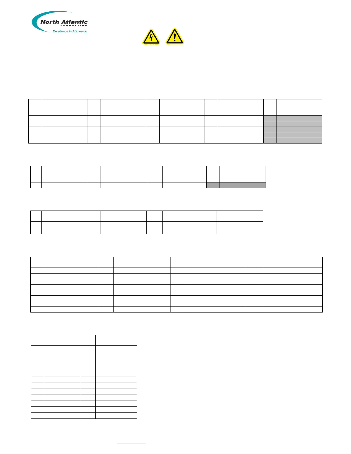
Safety Summary
This symbol is intended to alert the presence of un-insulated dangerous voltage and shock
hazard if misuse or improper handling.
This symbol is intended to alert the presence of important information in the literature
accompanying this device. All information should be read carefully to avoid misuse and potential
harm to the user and/or device.
GENERAL SAFETY NOTICES
The following general safety notices supplement the specific warnings and cautions appearing elsewhere in the
manual. They are recommended precautions that must be understood and applied during operation and
maintenance of the instrument covered herein.
REPAIR
DO NOT ATTEMPT REPAIR. Under no circumstances should repair of energized instrument be attempted. All
repairs to this instrument must be accomplished at the Factory.
HIGH VOLTAGE
HIGH VOLTAGE is used in the operation of this equipment.
DEATH ON CONTACT may result if personnel fail to observe safety precautions. Learn the areas containing high
voltage on this equipment. Be careful not to contact high-voltage connections when installing, operating or
maintaining this instrument.
INPUT POWER ALWAYS ON
The design of the model 5330A is such that AC input power is continuously supplied to the power supply
independent of the front panel ON/OFF Switch. The primary means of disconnect is pulling the line cord from the
instrument
WARNINGS
North Atlantic Industries, Inc.
631.567.1100 / 631.567.1823 (fax)
6/12/2018
5330A Operations Manual Rev A6
110 Wilbur Place, Bohemia, NY 11716
www.naii.com
Cage Code: 0VGU1
Page 6 of 24
Interfaces, Communication
The 5330A includes several different interfaces that include Ethernet, USB, & IEEE-488 and a 78 pin interface connector.
When a replacement for the legacy 5330 is required, conversion cable (07-0022) must be ordered as a separate item. When a
replacement for the legacy 5310 is required the 78 pin connector is replaced with a 50 pin connector that mimics the
previously supplied units. Pin out data, for the various configurations, is shown below.
Detailed programming commands/information is included in “5330A Programmer’s Reference Guide”. The Ethernet and
the USB connectors are industry standard.
5330A J1 CONNECTOR, PIN DESIGNATIONS
HDL78SL; Mate 78 pin male (See Accessories)
Pin
Designation
Pin
Designation
Pin
Designation
Pin
Designation
Pin
Designation
13
RHI-OUT
32
RHI-SENSE OUT
40
CHASSIS GND
59
S2-OUT CH1
78
S4-OUT CH1
14
S1-SENSE CH2
34
S3-SENSE CH2
52
RLO –OUT
71
RLO-OUT SENSE
15
S1-OUT CH2
35
S3-OUT CH2
53
S4-SENSE CH2
73
S2 SENSE CH2
16
RHI-IN CH2
36
RLO-IN CH2
54
S4-OUT CH2
74
S2-OUT CH2
19
S3-SENSE CH1
38
S1-SENSE CH1
56
RHI-IN CH1
76
RLO IN CH1
20
S3-OUT-CH1
39
S1-OUT CH1
58
S2 SENSE CH1
77
S4-SENSE CH1
Note: Do not connect to any non-designated pins
5330 J1 CONNECTOR, PIN DESIGNATIONS (See P/N)
DE9PP; Mate DE9S or equivalent
Pin
Designation
Pin
Designation
Pin
Designation
Pin
Designation
3
S1-OUT CH1
5
RLO IN CH1
7
S4-OUT CH1
9
RHI -115V CH1 IN
4
S2-OUT CH1
6
RHI –26V CH1 IN
8
S3-OUT-CH1
Note: Do not connect to any non-designated pins
5330 J3 CONNECTOR, PIN DESIGNATIONS
DD50P; Mate DD50S or equivalent
Pin
Designation
Pin
Designation
Pin
Designation
Pin
Designation
3
CHASSIS GND
19
S4-OUT CH1
34
S1-OUT CH1
37
RHI -115V CH1 IN
18
S2-OUT CH1
20
RLO IN CH1
35
S3-OUT-CH1
38
RHI –26V CH1 IN
Note: Do not connect to any non-designated pins
5310 J1 CONNECTOR, PIN DESIGNATIONS (See P/N)
DD50P; Mate DD50S or equivalent
Pin
Designation
Pin
Designation
Pin
Designation
Pin
Designation
1
SYN-RSL-SEL
16
BCD 40° / BIN 22.5°
31
BCD 4° / BIN 1.406°
41
LL1
4
CHASSIS GND
17
BCD 200° / BIN 180°
32
BCD 20° / BIN 11.25°
42
LL2
6
STROBE
18
S2-OUT CH1
33
BCD 100° / BIN 90°
45
BCD 0.01° / BIN 0.0014°
9
DIGITAL GROUND
19
S4-OUT CH1
34
S1-OUT CH1
46
BCD 0.08° / BIN 0.011°
12
BCD .04° / BIN 0.005°
20
RLO IN CH1
35
S3-OUT-CH1
47
BCD 0.4° / BIN 0.088°
13
BCD 0.2° / BIN 0.044°
28
BCD 0.02° / BIN 0.0027°
37
RHI -115V CH1 IN
48
BCD 2° / BIN 0.703°
14
BCD 1° / BIN 0.352°
29
BCD 0.1° / BIN 0.022°
38
RHI –26V CH1 IN
49
BCD 10° / BIN 5.625°
15
BCD 8° / BIN 2.813°
30
BCD 0.8° / BIN 0.176°
40
REF LEVEL SELECT
50
BCD 80° / BIN 45°
Note: Do not connect to any non-designated pins
J2 CONNECTOR, IEEE- 488 PIN DESIGNATIONS
Standard IEEE Interface Connector
Pin
Designation
Pin
Designation
1
DIO1
13
DIO5
2
DIO2
14
DIO6
3
DIO3
15
DIO7
4
DIO4
16
DIO8
5
EOI
17
REN
6
DAV
18
Gnd., DAV
7
NRFD
19
Gnd., NRFD
8
NDAC
20
Gnd., NDAC
9
IFC
21
Gnd., IFC
10
SRQ
22
Gnd., SRQ
11
ATN
23
Gnd., ATN
12
Shield
24
Gnd., Logic
J3 CONNECTOR:
USB-A (USB 2.0) Rear Connector, for communications only
Ethernet (10/100/1000 Base-TX)
J4 CONNECTOR:
USB-A Front Panel Connector for Optical Mouse only

North Atlantic Industries, Inc.
631.567.1100 / 631.567.1823 (fax)
6/12/2018
5330A Operations Manual Rev A6
110 Wilbur Place, Bohemia, NY 11716
www.naii.com
Cage Code: 0VGU1
Page 7 of 24
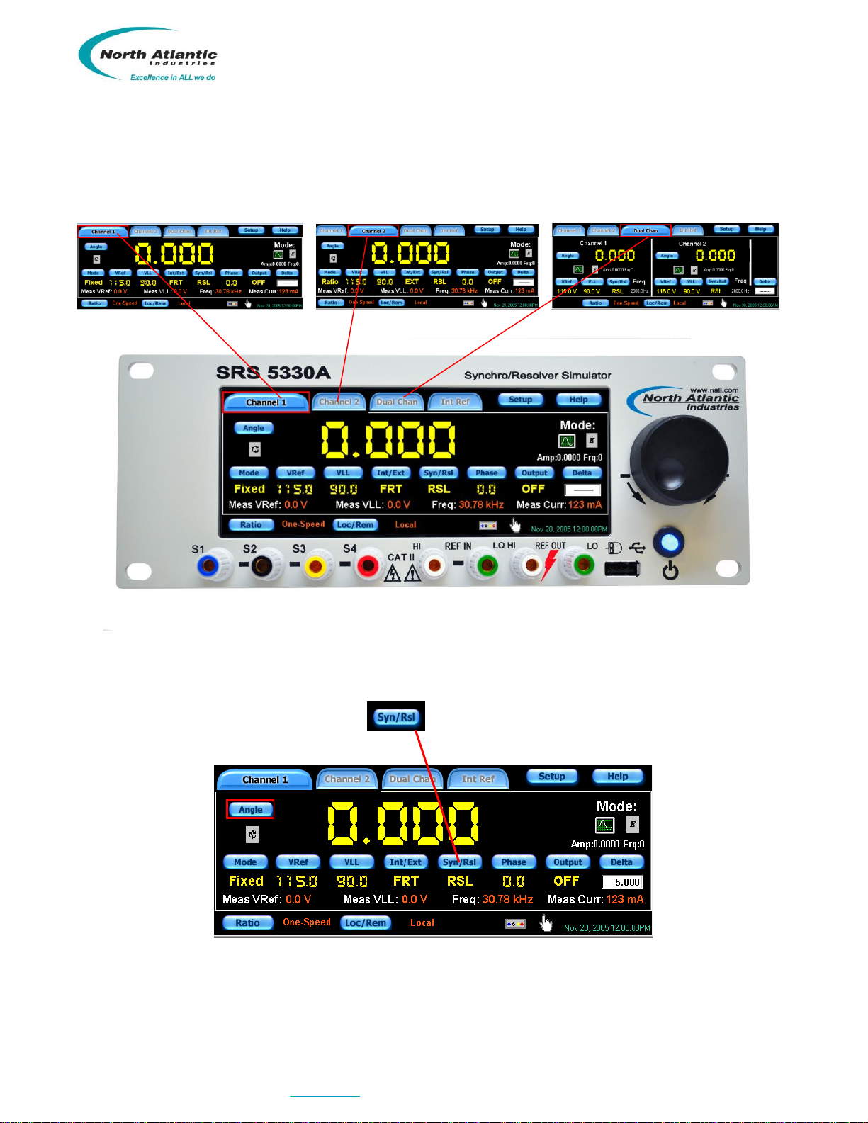
Controls & Indicators, General Description
Figure 1 –Front Panel Controls & Connections
Figure 2 –Indicators on the front panel main display of the 5330A
Channel
Output
Enable
Phase Offset
Set/Display
Synchro
Resolver
Set/ Display
Reference
Source Select:
INT/EXT
FRT/BCK
Setup
Multi-Speed
Ratio
Indicator
Main
Power
Button
Angle SET
(Knob)
External
Reference
Input (front)
Internal
Reference
Output (front)
Angle SET
(Direct input)
Setup Menu
Channel
Select
Tabs
Internal
Ref Control
Setup
On-Screen
Help Guide
Dynamic
Mode
Control
Increment /
Setup Knob
(Jog-wheel)
USB connector
for optical
mouse only
Touchscreen
Enabled/
Disabled
Ch1 Output
SYN / RSL
Front Panel
Mode Select:
Fixed or
Ratiometric
Multi-Speed
Ratio
Set-Up
Setup
Expected
Reference
Set / Display
Ch1 Output
From Front
Panel /Back
Time & Date
display
Measured
Signal (REF)
Current
Delta
Control
Line-to-Line
Output
Voltage
Set / Display
Measured
Signal (REF)
Frequency
Measured
Reference
Voltage
Measured
Output VLL
Local/Remote
Set/Display
North Atlantic Industries, Inc.
631.567.1100 / 631.567.1823 (fax)
6/12/2018
5330A Operations Manual Rev A6
110 Wilbur Place, Bohemia, NY 11716
www.naii.com
Cage Code: 0VGU1
Page 8 of 24
Channel Selection
To select channel 1, channel 2 or dual channel configuration, press corresponding tab by using either the touch
screen, mouse or increment/setup knob. Below figures show each channel select button along with the
corresponding channel display. Selected configuration is highlighted.
Figure 3 –Channel Selection
Synchro/Resolver Mode Select
On any channel screen, toggle the Syn/Rsl button to select either Synchro or Resolver format. The
selected format will be displayed below the button.
Figure 4 –Synchro / Resolver Mode Select
North Atlantic Industries, Inc.
631.567.1100 / 631.567.1823 (fax)
6/12/2018
5330A Operations Manual Rev A6
110 Wilbur Place, Bohemia, NY 11716
www.naii.com
Cage Code: 0VGU1
Page 9 of 24
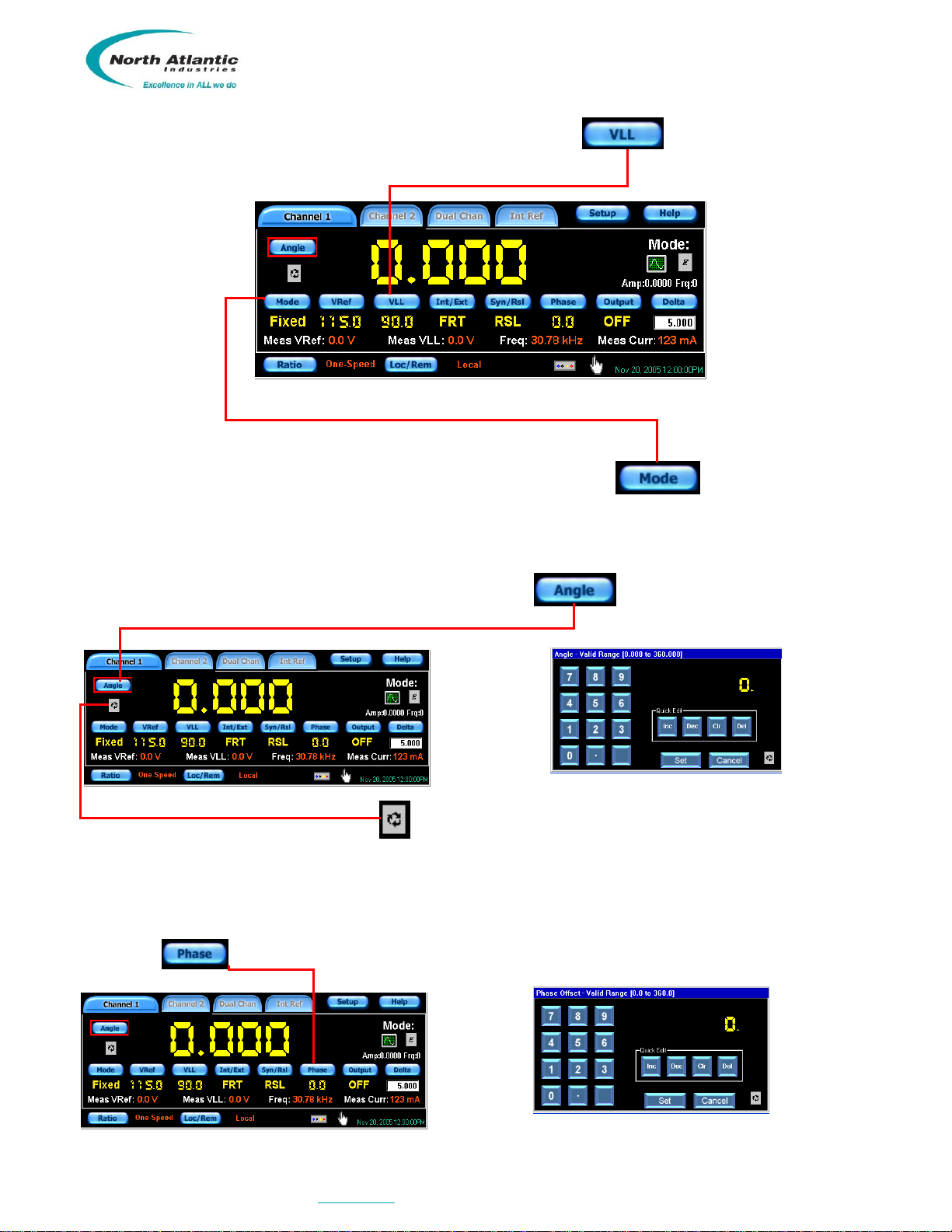
VLL (Voltage Line-to-Line) Output Select
Each channel must be set to a desired output voltage (VLL). When the button is pressed, enter the
desired output voltage (VLL) for each channel. Then specify either “FIXED” or “RATIOMETRIC” mode. (See next
illustration)
Figure 5 –VLL Output select & Fixed/Ratiometric mode
Fixed/Ratiometric (Voltage output mode select)
Each channel can be set for “FIXED” or “RATIOMETRIC” output. When the button is pressed, the
output mode will toggle between “FIXED” and “RATIOMETRIC”. When set for “FIXED”, the output voltage (VLL)
will remain constant at the set VLL voltage. When set for “RATIOMETRIC”, the output signal voltage (VLL) will vary
directly with changes in the applied reference voltage.
ANGLE set
Each channel can be programmed to various angles. When the button is pressed, enter the desired
angle using the touch screen, mouse, or incremental knob.
Figure 6 –Angle Set
Alternatively, when the “ANGLE SET” icon is pressed, the unit will respond to the “Increment / Setup” knob
and will step the output angle according to the value set up in the “Delta screen” panel.
PHASE Offset
Each channel can be programmed to a specific phase shift between the output and the reference. Typically, this
is utilized to closely match the phase difference exhibited by a true Synchro.
When the button is pressed, enter the required phase shift between the output signal and reference
source. Press the “Set”button to complete.
Figure 7 –Phase Offset Control
North Atlantic Industries, Inc.
631.567.1100 / 631.567.1823 (fax)
6/12/2018
5330A Operations Manual Rev A6
110 Wilbur Place, Bohemia, NY 11716
www.naii.com
Cage Code: 0VGU1
Page 10 of 24
Channel Output, Enable
To turn the output amplifiers “ON”/“OFF”, press the button. The output button will toggle the outputs
“ON” or “OFF”.
Figure 8 –Output Enable
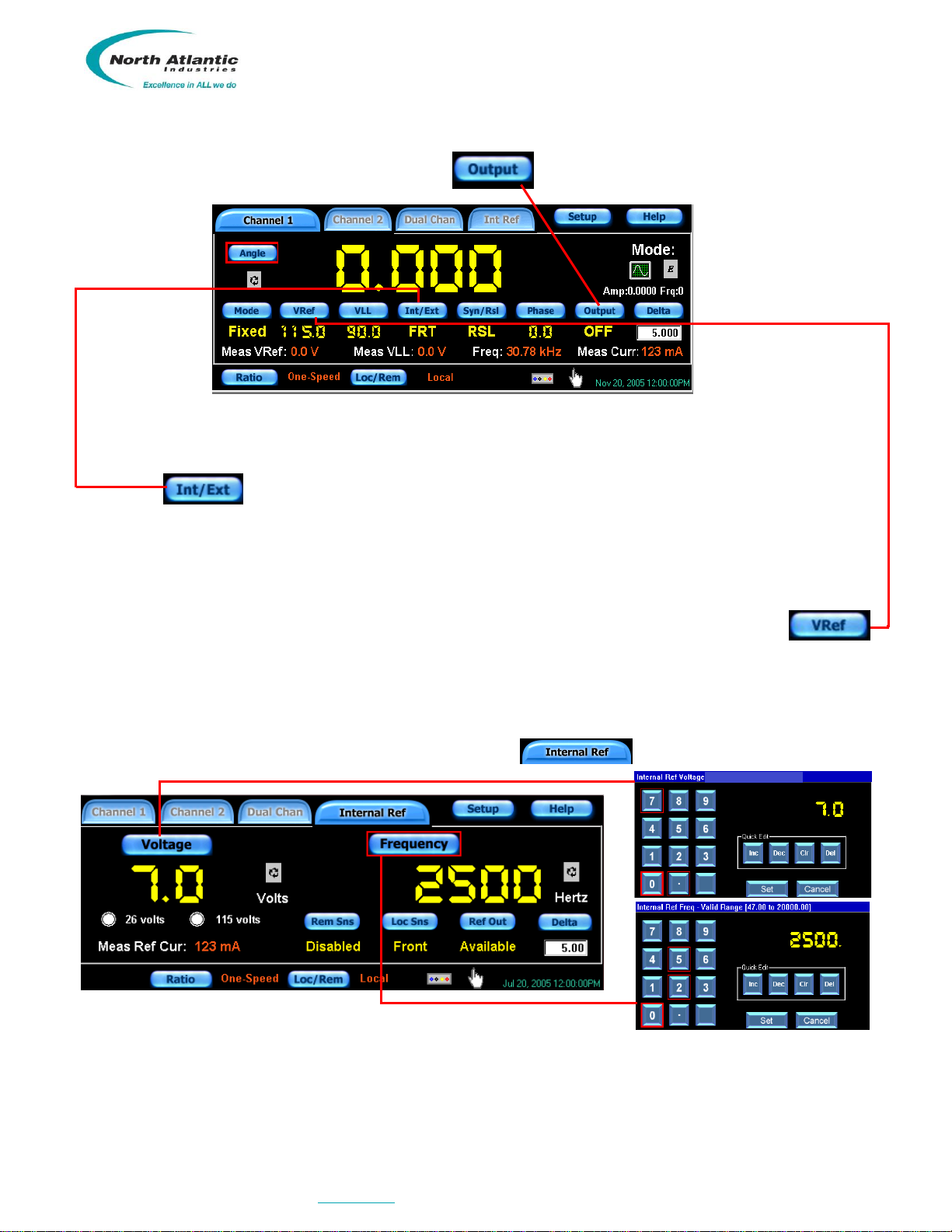
INT/EXT (Reference Source Select)
Each channel must be programmed to accept a REFERENCE signal from either the external or the optional
internal.
When the button is pressed, for CH. 1, the Reference Source is selectable between “INT” (Optional
Internal Reference as source), “FRT” (External reference source through the front panel) or “BCK” (External
reference source through the J1 connector. For CH. 2, the Reference Source is selectable between “INT”
(Optional Internal Reference as source) or “EXT” (external reference source). NOTE: CH. 2 External reference
source is only applicable through the J1 connector.
VREF (External Reference Voltage Set)
When an external reference is specified, the anticipated VREF must be entered by pressing the VREF
button and entering the appropriate voltage. This needs to be done in order to let the Simulator set a
transformation ratio (or proportion between REF voltage input and output voltage VLL) when the “RATIOMETRIC”
output mode is selected.
Internal Reference Setup
If internal reference option is installed in the 5330A, press the Internal Ref button that will bring
up the sub-screens for controlling the reference:
Figure 9 –Internal Reference Setup
Set the internal reference generator voltage and frequency parameters, using the setup screens shown above.
When done, press any of the channel buttons or any other function to exit this setup menu.
To enable output of the optional on-board reference source, insure the “Ref Out Signal:” displays “Available”.

North Atlantic Industries, Inc.
631.567.1100 / 631.567.1823 (fax)
6/12/2018
5330A Operations Manual Rev A6
110 Wilbur Place, Bohemia, NY 11716
www.naii.com
Cage Code: 0VGU1
Page 11 of 24
The Remote Sense button can be “Enabled” or “Disabled”. The Remote Sense setting is applicable
only when the Local Sense is configured to the “Back”.
The Local Sense button can be configured for the “Front” or the “Back”. When the Local Sense is
configured for the “Front” the Remote Sense setting is ignored.
Remote Sense Setup
This screen allows for the remote sensing of each SIM channel and the reference supply.
Remote Sense Screen
Over Current
An “Over Current” occurs when either the reference or one of the SIM channels is overloaded. When an overload
is detected, the D/S will stop driving temporarily and will attempt to turn on every second for approximately 10
seconds, and if an over current is still present, the output will be disconnected and the corresponding tab will start
to blink red.
To reset this condition, once the cause of the over current has been resolved, press the tab that is blinking red
and the following “Over Current” screen will appear; press corresponding “Clear” button.
Over Current Screen

North Atlantic Industries, Inc.
631.567.1100 / 631.567.1823 (fax)
6/12/2018
5330A Operations Manual Rev A6
110 Wilbur Place, Bohemia, NY 11716
www.naii.com
Cage Code: 0VGU1
Page 12 of 24
DELTA Screen Panel
The Delta Screen Panel sets the parameters for the “Increment/Setup” knob. When the button is
pressed, the “Delta Screen” panel will become visible. Enter the desired values. The entered values represent the
resolution that the knob will control for the particular function selected. For this example, assume that the “ANGLE
SET” icon was pressed and set to 5 degrees. The “Increment/Setup” control knob, when turned clockwise, will
increase the output angle in 5 degree increments and when turned counterclockwise, will decrease the output
angle in 5 degree increments
Figure 10 –Delta Screen Panel
Ratio (Multi-Speed) Mode
Two outputs of the 5330A can be combined with a ratio of 2 to 255.
Figure 11 –Ratio (Multi-Speed) Mode
Select the Ratio button to enter the ratio menu and select the required ratio
Figure 12 –Ratio Select
Refer to the above left menu display. Assume that two-speed is selected with a ratio of 2:1 (Value may be
entered via keypad or the ‘Quick Edit’ Increment/Decrement buttons. Values may also be cleared or deleted using
the quick edit keypad. Once value is selected, hit “Set”button and unit will return to the channel display. Now
refer to the display on the right and note that the ratio that you have set is displayed next to the Ratio button. Also
note that the channel select tabs at the top have changed from Channel 1 to Coarse, and from Channel 2 to Fine.
Channel 2 controls are now “locked out” and the display will be “grayed”. Channel 1 will output the “coarse” signal
and channel 2 will output the “fine” signal. Any commanded angle will now set Ch.1 (coarse) and Ch.2 (fine) will
automatically be set to the commanded angle multiplied by the programmed ratio.
North Atlantic Industries, Inc.
631.567.1100 / 631.567.1823 (fax)
6/12/2018
5330A Operations Manual Rev A6
110 Wilbur Place, Bohemia, NY 11716
www.naii.com
Cage Code: 0VGU1
Page 13 of 24
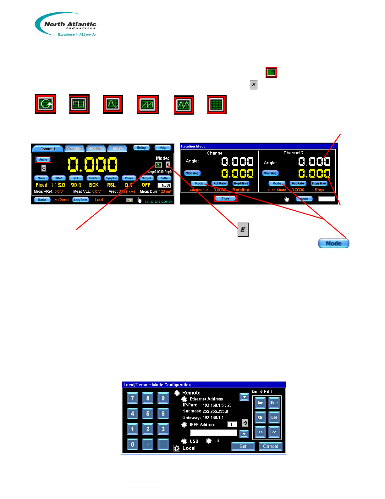
DYNAMIC Mode Control Panel
A specific dynamic mode can be selected by toggling the Dynamic Control button until the desired format is
displayed on the face of that button. Then, press the parameter control button to get the parameter sub screens.
.
Rotation Step Sine Ramp Saw tooth No function
For example:
Figure 13 –Rotation Mode
When the MODE rotation icon is selected, pressing the parameter button will bring forth the rotation mode
sub screen that can be programmed for either continuous or start/stop rotation by toggling the buttons
When continuous rotation is selected, toggling the Stop/Start will cause the selected to rotate until stopped.
When Start/Stop rotation is selected, the output will start rotating from the ‘Start Angle” until it reaches the
programmed “Stop Angle”. When completed, the “Stop/Start” will display “Stop”.
PROGRAMMING
Remote programming / Legacy 5330/5310 support (refer to 5330AA Programmer’s Reference Guide)
Compatibility to 5330/5310 SRSs
The 5330A will provide language compatibility to the following 5330/5310 systems:
5330 Native
5310 Native (BCD)
5310 Native (Binary)
This unit may be remotely controlled through a USB, Ethernet, IEEE-488 port or the J1 parallel connector.
Figure 14 –Remote Operation
Start Angle
Stop Angle
North Atlantic Industries, Inc.
631.567.1100 / 631.567.1823 (fax)
6/12/2018
5330A Operations Manual Rev A6
110 Wilbur Place, Bohemia, NY 11716
www.naii.com
Cage Code: 0VGU1
Page 14 of 24
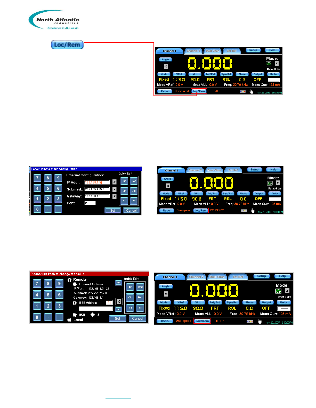
Press the button on any of the Channel
Displays, to enter the remote configuration menu as
shown above. Select remote button, and then the
desired port or J1.
USB Port Selection
Selection of the USB port is accomplished by simply
pressing the USB button. Once entered, hit
‘set’ button and unit will return to main display.
Note: the USB is now displayed next to the Loc/Rem button
Figure 15 –USB Port Selection
Ethernet Port Selection
Selection of the Ethernet port is accomplished by pressing the Ethernet address button and then adding a valid IP
address, Submask and Gateway address for your Ethernet network. The Ethernet Port used by the 5330A is
always Port 23. When completed, hit ‘set’ button and unit goes back to main display
Figure 16 –Ethernet Port Selection
IEEE-488 Port Selection
Selection of the IEEE-488 port is accomplished by pressing the IEEE-488 address button and then adding a valid
address. When completed, hit ‘set’ button and unit goes back to main display
Figure 17 –IEEE-488 Port Selection
Note: ETHERNET is now displayed next to the Loc/Rem button
Note: IEEE is now displayed next to the Loc/Rem button
North Atlantic Industries, Inc.
631.567.1100 / 631.567.1823 (fax)
6/12/2018
5330A Operations Manual Rev A6
110 Wilbur Place, Bohemia, NY 11716
www.naii.com
Cage Code: 0VGU1
Page 15 of 24
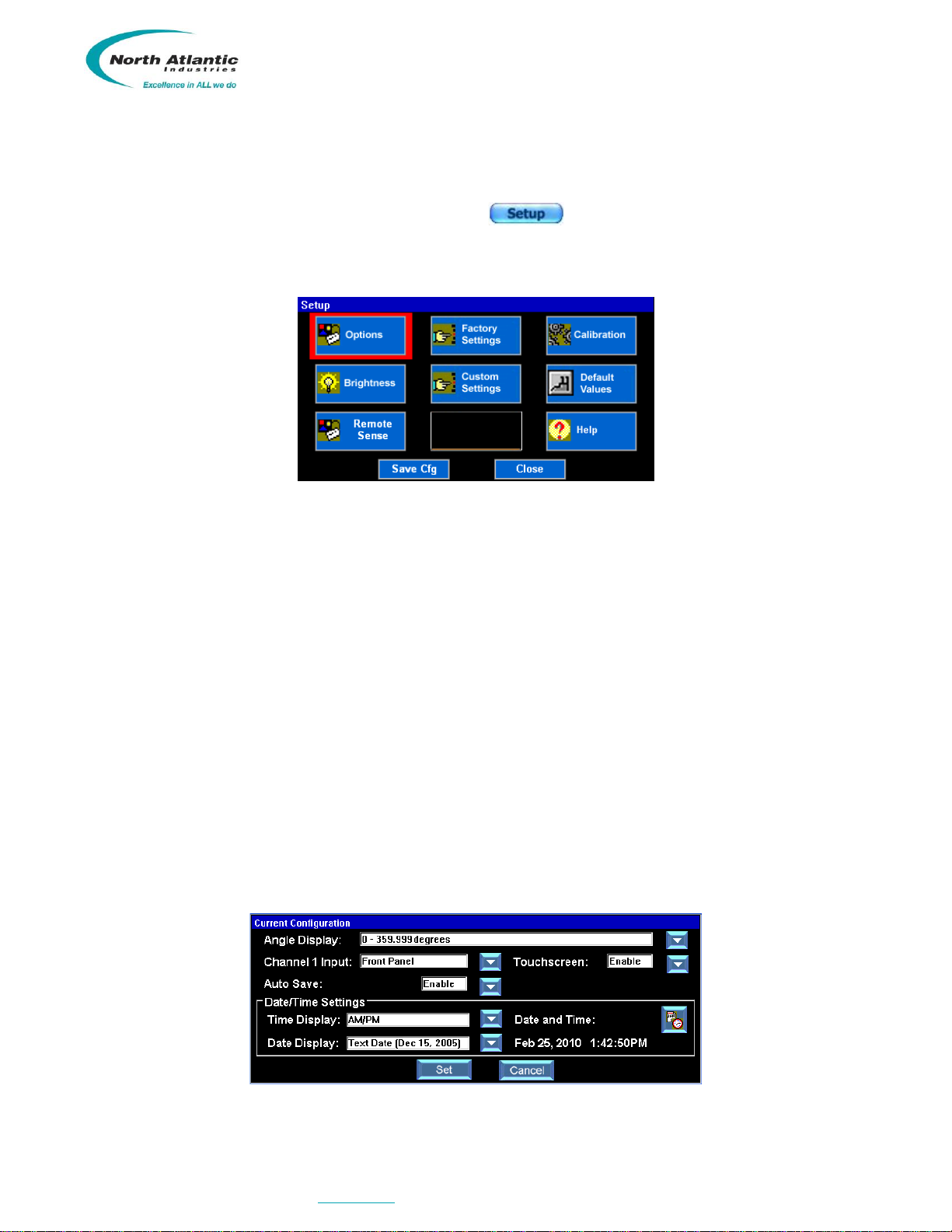
Setup Menus
The 5330A setup menu accesses features of the Simulator that allows the user to easily configure it through the
front panel.
The setup menu is accessed by pressing the Setup button at the top of the main display screen. As
shown by the screen below, there are ten choices in the setup menu. The section below describes
each setup menu option.
Figure 18 –Setup Menus
A sample of the Options Menu is shown below. This menu allows configuration of the following:
Angle Display may be configured for the following parameters
o0 to 359.9999 degrees
o-179.9999 to 179.9999 degrees
Channel 1 Input may be configured for the following parameters
oFront Panel Output
oBack Connector Output (J1)
Touch screen
oEnabled
oDisabled (re-enable using the Increment /Setup knob or mouse to select Options menu)
Auto Save
oEnabled –5330A will automatically save the 5330A configuration parameters when the user
powers down the Instrument
oDisabled
Date/Time Settings enable configuration of the following parameters:
oTime Display Format either AM/PM or Military
oDate Display Format either Text Date or Numeric Only Date
oSetting of Time and Date
Figure 19 –Options Menu

North Atlantic Industries, Inc.
631.567.1100 / 631.567.1823 (fax)
6/12/2018
5330A Operations Manual Rev A6
110 Wilbur Place, Bohemia, NY 11716
www.naii.com
Cage Code: 0VGU1
Page 16 of 24
The Factory Settings screen is shown below. This screen contains 4 sets of parameters that are configured at
the factory. These parameters include the settings for reference source, reference voltage, reference frequency
and Synchro/Resolver configuration. The pre-set parameter is chosen by simply selecting the button on the left,
followed by the Load button. Once completed, the Simulator will return to the main display screen and
the values are stored until changed.
Figure 20 –Factory Setting
The Custom Settings screen, shown below, will save up to 9 parameter settings. This is accomplished by saving
those that are currently on the main screens. Select the button to the left of the numbers 1 –9 followed by
pressing the ‘Save Current’ button. To use the previously saved parameters select the button on
the left, followed by the ‘Load’button.
Figure 21 –Custom Settings
The Brightness Control screen is shown below. Front panel backlight brightness is adjustable from 20% to 100%
Figure 22 –Brightness Control

North Atlantic Industries, Inc.
631.567.1100 / 631.567.1823 (fax)
6/12/2018
5330A Operations Manual Rev A6
110 Wilbur Place, Bohemia, NY 11716
www.naii.com
Cage Code: 0VGU1
Page 17 of 24
The Calibration Menu, shown below,contains a calibration routine for the Touch screen display and a calibration
routine for the Instrument.
The “Touchscreen Calibration”will give prompts to the user to touch the screen at various places in order to
correctly center the screen. At the end, “Calibration Complete” will be displayed.
The “Unit Calibration”will perform a full, ‘off-line’ self-calibration that does not require user intervention or external
equipment; duration is approximately 25 minutes.
Figure 23 –Calibration Menu
Shown below are examples of the Help Menu screens. The help menu gives things such as specification
summaries, descriptions of available buttons and descriptions of available functions. The Help Menu screen
shows the unit’s serial number, date code, MAC address, model information and firmware revision.
Figure 24 –Help Menus
Default Values screen enables user to restore the 5330A factory settings.
Figure 25 –Default Values
North Atlantic Industries, Inc.
631.567.1100 / 631.567.1823 (fax)
6/12/2018
5330A Operations Manual Rev A6
110 Wilbur Place, Bohemia, NY 11716
www.naii.com
Cage Code: 0VGU1
Page 18 of 24
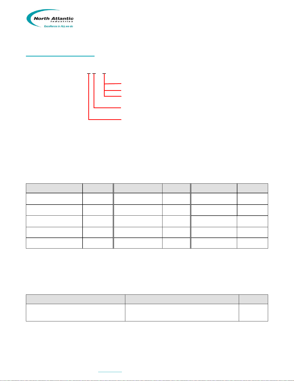
ORDERING INFORMATION
Part number: 5330A - -
Leave blank for standard 5330A
Add ‘30’ ** for a for a replacement for all legacy 5330 models
Add ‘10’ for a for a replacement for all legacy 5310 models
Add ‘0’ for no reference supply; add ‘R’ for one reference supply
Add ‘1’ for single channel; add ‘2’ for two channels
**Note: To mimic the connector pin-out of the 5330, a separate conversion cable (P/N 07-0022) must be ordered.
Accessories:
Included with the 5330A is an accessory kit NAI part number 5330A-ACCESSORY-KIT.
Kit includes the following items:
5330A- Accessory Kit
NAI P/N
5310 Accessory Kit
NAI P/N
5330 Accessory Kit
NAI P/N
78 Pin Mating connector
09-0001
50 Pin Mating
connector
05-0053
Fuse, 5 x 20mm,
2A, slow-blow (2)
99-0146
Shell
P/O 09-0001
Shell
05-0060
Line Cord
202-0002
Fuse, 5 x 20mm, 2A,
slow-blow (2)
99-0146
Fuse, 5 x 20mm, 2A,
slow-blow (2)
99-0146
Two spare fan
filters
111-0005
Line Cord
202-0002
Line Cord
202-0002
Two spare fan filters
111-0005
Two spare fan filters
111-0005
Optional Mounting Accessory
The 5330A can be ordered with mounting adapters for one unit in a standard 19-inch equipment rack. The table
below describes full rack mounting accessory:
Type of Mount
Description
NAI P/N
Full Rack Mounting
Mounts one unit in a 19-inch rack
783893
North Atlantic Industries, Inc.
631.567.1100 / 631.567.1823 (fax)
6/12/2018
5330A Operations Manual Rev A6
110 Wilbur Place, Bohemia, NY 11716
www.naii.com
Cage Code: 0VGU1
Page 19 of 24
INSTALLATION AND MAINTENANCE
UNPACKING AND INSPECTION
This instrument has been thoroughly tested, inspected, and evaluated at the factory before shipment. Care has been
taken in the design of the wrapping and packaging material to insure that no damage results from mishandling.
Inspect the instrument externally. Check the front panel for signs of damage to the switches, knobs, terminal jacks
and display. Check the power switch and thumbwheel for smooth operation. Switch buttons should be secure.
Check the condition of the connectors and fuse on the back panel. Check covers for damage and loose screws. If
the instrument passes this inspection, install it and place it in operation. If damage is found, please contact NAI
customer service through the NAI web-site, www.naii.com or call (631)-567-1100.
SHIPPING
The original shipping containers, along with their appropriate blocking and isolating material are the preferred
method of packing. Any other suitably strong container may be used provided the product is wrapped in a sealed
plastic bag and surrounded with an appropriate amount of shock absorbing material to cushion firmly, preventing
movement inside the container. Special attention should be paid to protection of the front panel touch screen
display and terminal jacks.
INSTALLATION
Rack Mounting Instructions:
The Model 5330A may be mounted in a standard 19-inch equipment with a full rack mounting adapter, NAI p/n
783893. It requires no special cooling equipment. Mount the unit so that air flows freely around it, particularly the
rear panel used to transmit the power supply heat to the ambient air. Connect cables, turn on power switch and
wait for unit to initialize.
Bench Installation:
For bench top use, the 5330A has Tilt stand and (4) rubber feet. Select an appropriate area that permits access to
front and rear panels of SRS. Place SRS on bench, connect cables, turn on power switch and wait for unit to
initialize
MAINTENANCE
Input AC Power Fuse(s):
Fuses are contained within the AC Input Connector. Insure AC Power cord is disconnected. Replacement of the
fuses is accomplished by removing the fuse holder located within the AC Input Connector (external, rear panel of
unit). Replace with fuses equivalent to factory installed specifications. Reference the Mechanical Outline.
North Atlantic Industries, Inc.
631.567.1100 / 631.567.1823 (fax)
6/12/2018
5330A Operations Manual Rev A6
110 Wilbur Place, Bohemia, NY 11716
www.naii.com
Cage Code: 0VGU1
Page 20 of 24
Repair
DO NOT ATTEMPT REPAIRS. All repairs to this instrument must be accomplished at the Factory.
High Voltage is used in the operation of this equipment.
DEATH ON CONTACT may result if personnel fail to observe safety precautions. Be careful not to
contact high-voltage connections when installing, operating or maintaining this instrument.
Input Power Always On
AC input power is continuously supplied to the power supply independent of the front panel ON/OFF Switch. The
primary means of disconnect is to remove the line cord from the instrument
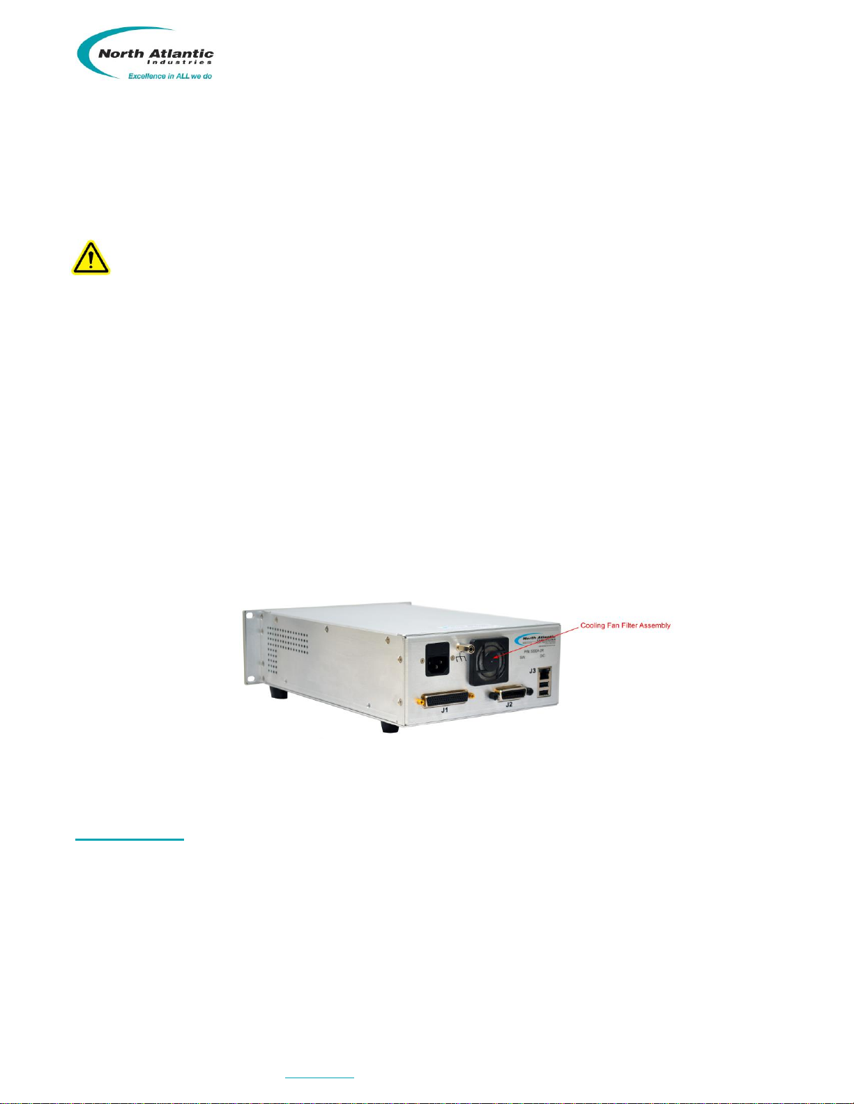
Rear Panel Cooling Fan Filter
The unit is equipped with a cooling fan installed on the rear panel of the unit. The Fan Filter Assembly is user
accessible and the Fan Filter has been mounted for easy removal for cleaning and/or replacement. Periodic
inspection (duration varies upon unit environmental use) of the condition of the filter is recommended to insure
proper air flow circulation and reduction of contaminants. If filter is clogged or deteriorated, cleaning and/or
replacement is recommended. The Fan Filter is held in place by a filter shroud insert. Before any maintenance is
performed, insure that the power cord has been disconnected from the unit. The filter shroud can be removed (no
special tools required) by gentling pulling and disconnecting from the shroud assembly (insert is held in place by
molded retainers in the shroud). The filter can be accessed at this point for maintenance. Two spare replacement
filters are supplied in the accessory kit.
Figure 26 –Maintenance; Cooling Fan Filter
CALIBRATION
Self-calibration
The unit is self-calibrating. When unit is turned on it will automatically initiate self-calibration. After warm-up of 15
minutes, unit will again automatically calibrate the channel or channels being used. Once calibrated, unit will
monitor usage. Should frequency or voltage of output signal change/commanded by more than 12.5%, unit will
automatically recalibrate the channel in use. Calibration takes about 2 seconds.
Calibration Verification
The model 5330A should have its calibration verified on an annual basis. Factory Calibration service is available on
request. If the instrument fails to meet its accuracy, it must be repaired. Repairs can only be done at the Factory.
Table of contents
Popular Laboratory Equipment manuals by other brands


COMINOX
COMINOX Sterilclave 6 B Speedy Service manual

Biotage
Biotage TurboVap 96 Dual user manual

INTELLICYT
INTELLICYT iQue SCREENER Hardware manual

Teledyne
Teledyne ACCQPrep HP125 Installation and operation guide

Leica BIOSYSTEMS
Leica BIOSYSTEMS SM2010 R Instructions for use

Thermo Scientific
Thermo Scientific Sorvall BP 8 instruction manual

Mecmesin
Mecmesin MultiTest-i Series Assembly and installation

Labconco
Labconco Protector XL 1124 Series user manual

Biotechne
Biotechne ProteinSimple Milo installation guide

cytiva
cytiva F9-R operating instructions

Agilent Technologies
Agilent Technologies 1260 Infinity II user manual

IKA
IKA ULTRA-TURRAX T 18 digital manual