BIO UV MP030 EL Manual
MP 030 EL NM GB Copyright BIO-UV - 29/01/2009
Marque, Modèles et Brevets déposés - Produits exclusifs
Page 1
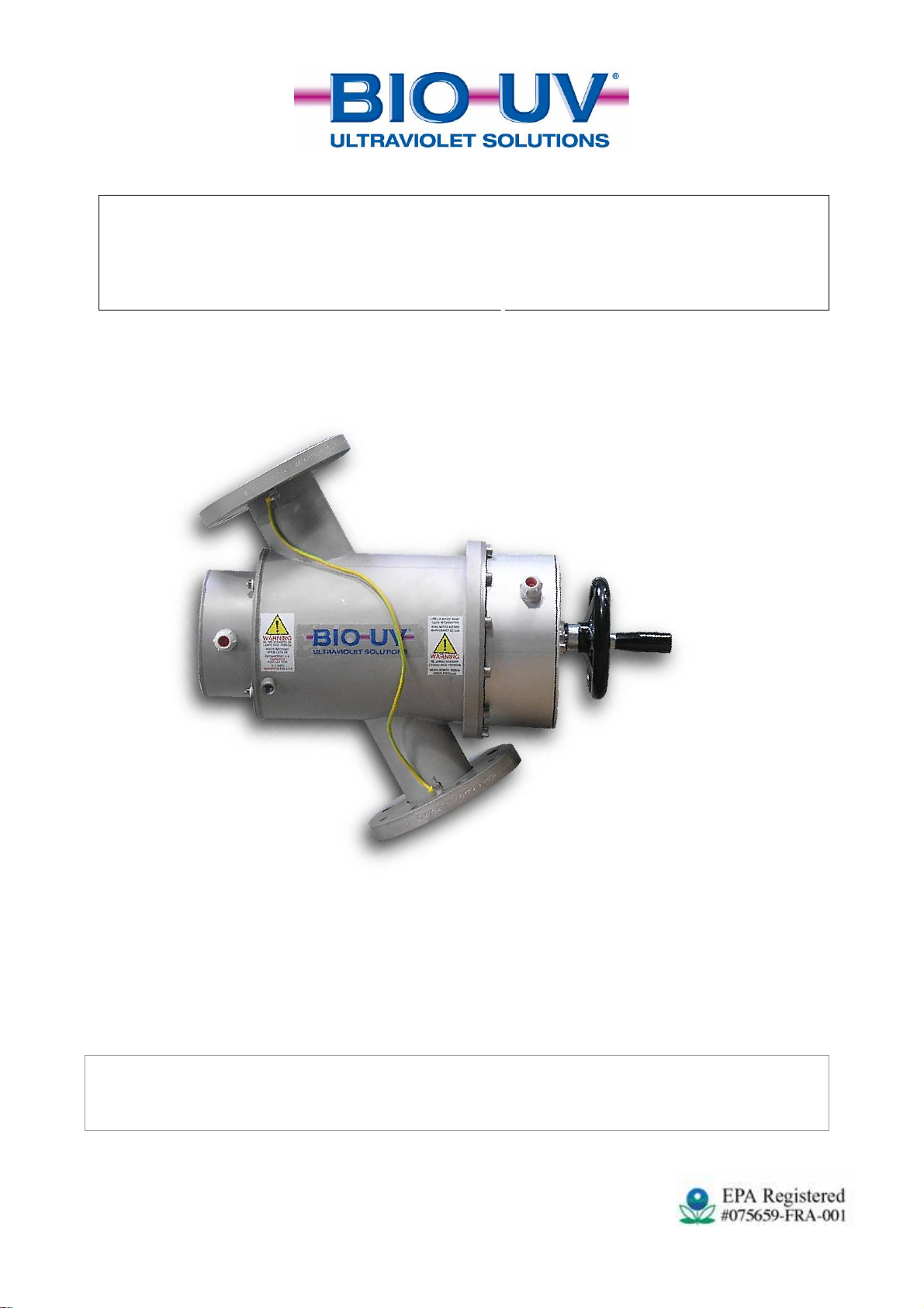
REACTOR USING MEDIUM PRESSURE LIGHT
MP030 EL
MANUAL CLEANING
(Picture MP 030)
INSTALLATION AND MAINTENANCE
MANUAL

MP 030 EL NM GB Copyright BIO-UV - 29/01/2009
Marque, Modèles et Brevets déposés - Produits exclusifs
Page 2
UVPS subsidiary of the BIO-UV
COMPLIANCE CERTIFICATE
CERTIFICATE OF CONFORMITY
BIO-UV and this subsidiary, hereby declares that the following products
BIO-UV MP Range
comply to the following standards:
NF EN 60439-1 (2000)
CEM: EN55015 (Ed.00) + A1 (Ed.01)
Number and year of EC stamp:
CG-03-006 dated 29/01/2003
LS-03-51003/NL dated 20/02/03
Benoît GILLMANN
Chairman and Managing Director of BIO-UV
Société BIO-UV SA
ZAC La Petite Camargue
34400 LUNEL France
Hotline: + 33 (0)890 71 03 70
(0,15€/min)

MP 030 EL NM GB Copyright BIO-UV - 29/01/2009
Marque, Modèles et Brevets déposés - Produits exclusifs
Page 3
We thank you for choosing a BIO-UV reactor.
Our equipment has been designed to give you reliable and safe operation for many years to come.
The BIO-UV reactors have been designed for speed and ease of installation.
Their design also makes them easy to maintain..
Read these instructions carefully in order to optimise the operation of your reactor.
CONTENTS : pages
A. TECHNICAL CHARACTERISTICS...............................................................................................4
B. MAINTENANCE FILE ......................................................................................................................6
C. WARNINGS AND SAFETY ..............................................................................................................7
D. INSTALLATION OF THE REACTOR............................................................................................9
E. FLOW SENSOR................................................................................................................................13
F. MANUAL OF THE MONITOR BIO-UV MIII .............................................................................14
G. ALARM CONTACT (OPTION)......................................................................................................17
H. OPERATION OF THE 4-20MA OUTPUT (OPTION).................................................................17
I. INSPECTIONS AND PREVENTIVE MAINTENANCE .............................................................18
J. CHANGING THE WIPER SEALS.................................................................................................22
K. ELECTRICAL UNIT........................................................................................................................23
L. BLOWN UP VIEW............................................................................................................................24
ANNEX 1: Clearance dimensions – Blown up view – Designation
ANNEX 2: Electrical diagrams

MP 030 EL NM GB Copyright BIO-UV - 29/01/2009
Marque, Modèles et Brevets déposés - Produits exclusifs
Page 4
A.TECHNICAL CHARACTERISTICS
MP030 EL RANGE 600 W 1 KW 3 KW
REACTOR
Material
Stainless steel 316L
Finish
Pickling and passivated
Maximum service pressure
3 bars
Weight (kg)
(1)
16
Ø and body length (mm)
204 x 276
Overall length (mm)
450
Volume (litres)
14,2
Connection type
Flange
Standard Connection
(2)
DN 80
ELECTRICAL UNIT
Type
Painted steel Painted steel
Dimensions (mm)
600 x 400 x 250 600 x 400 x 250
Weight (kg)
Power supply
Single-phase
240VAC
Power supply wiring
2G1.5mm² 2G2.5mm²
Earth cable
6 mm²
Differential protection
30 mA 30 mA
Thermo magnetic protection
10 A 2P 25 A 2P
Circuit breaker tripping curve
Curve C Curve C
Fuse
-
On / Off switch
Yes
Power on indicator light
Yes
UV lamp indicator light
Yes
Display
Monitor MIII
Protection index
IP 54
UV-C LAMP
Number of lamps
1 1 1
Electrical power
600 W 1 000 W 3 000 W
Unit UV-C power
90 W 150 W 375 W
Total UV-C power
90 W 150 W 375 W
Average lifetime
6 à 9 000 h 6 à 9 000 h 6 à 9 000 h
*operating continuously with one on/off per day.
Turning UV lamps on and off reduces their lifespan. A minimum time delay of 30 minutes must be
observed before turning a lamp back on again.
(1) Caution, with a cleaning system these values change.
(2) Except request specific to the order.

MP 030 EL NM GB Copyright BIO-UV - 29/01/2009
Marque, Modèles et Brevets déposés - Produits exclusifs
Page 5
TESTS OF ACCEPTANCE
Client:
Order number:
Unit designation:
Serial number:
Date:
ELECTRICAL SECTION:
Test date:
Wiring carried out by:
Protection classification: IP 54
Observation:…………………………………………………………………………………………………
………………………………………………………………………………………………………………
………………………………………………………………………………………………………………
………………………………………………………………………………………………………………
…………
MECHANICAL SECTION :
DESIGNATION REFERENCE
Quartz
UVC Lamp
Quartz joint
Wiper joint
Motor / electric jack
Dimensions between flanges
Bri e
Re uction
Checker’s name: Signature:
MP 030 EL NM GB Copyright BIO-UV - 29/01/2009
Marque, Modèles et Brevets déposés - Produits exclusifs
Page 6
B. MAINTENANCE FILE
CAUTION:
This sheet must be kept up to date.
It provides a record of the reactor’s operating cycle.
Date Action By

MP 030 EL NM GB Copyright BIO-UV - 29/01/2009
Marque, Modèles et Brevets déposés - Produits exclusifs
Page 7
C.WARNINGS AND SAFETY
BIO-UV reactors are ready to install, no works is required inside the reactor.
Read all the instructions in this manual before switching on the BIO-UV appliance.
INSTALLATION
RECOMMANDATIONS
The reactor must be installed:
-in a technical room, protected from light and rain,
-after the filter(s),
-in a dry zone, ambient humidity must be < 80%.
The installation zone temperature must be within 0°C and 40°C.
Keep any sources of hydrochloric acid vapours away from the installation.
The electrical unit should be positioned:
-so that it is protected from water,
-at eye level.
The air vent of fan must not be obstructed.
The cable length between the UV reactor and its electrical unit must not be modified.
Provide for sufficient space for reactor maintenance.
The reactor must be installed so that the UV lamp is in a horizontal position.
●The equipment must always be filled with water when operating and the
air must be bled out of it.
We recommend the presence of a by-pass.
●Before accessing the connection terminals, ensure that all supply circuits
are disconnected.
●The reactor installation as a whole must be protected with a suitably adapted
circuit breaker.
(See A. Technical characteristics)
●Check that cable complies with legislation and the required power level.
(See A. Technical characteristics)
●If, for installation reasons, the power supply cables connecting the cabinet to
the reactor have to be shortened, take care to fully crimp the new end fittings
at each end of the cables.

MP 030 EL NM GB Copyright BIO-UV - 29/01/2009
Marque, Modèles et Brevets déposés - Produits exclusifs
Page 8
USE AND MAINTENANCE
●Allow the ultraviolet lamp to cool for at least 30 minutes before handling.
●Never look at the ultraviolet lamps when lit. This may cause severe injuries
or burns and may even lead to loss of eyesight.
●Do not touch the ultraviolet lamp with bare hands, as these would leave
impurities that shorten the life of the lamp. If you do touch it: clean with alcohol
or white vinegar.
●Never unscrew the quartz tube sealing nut when the reactor is on load as the
quartz tube could be blown out of the reactor with force and injure you.
●Do not use the reactor if the power supply wire is worn or damaged. In this
case it should be replaced.
●If the connecting cable between the reactor and the electrical cabinet is
damaged, it must be replaced by a special cable available as a spare part.
●Even when stopped, power is present in the electrical unit so make sure
that the main power supply upstream of the electrical cabinet is switched off
before carrying out any work on the equipment.
●To avoid electric short-circuits, do not place the electric wires or the reactor in
the pool water or in any other maintenance or cleaning fluid.
●Do not restart the system until the electric unit, the covers exterior elements of
the reactor are correctly back in place.
●Do not use the BIO-UV reactor for any other use than that for which it was
designed.
MP 030 EL NM GB Copyright BIO-UV - 29/01/2009
Marque, Modèles et Brevets déposés - Produits exclusifs
Page 9
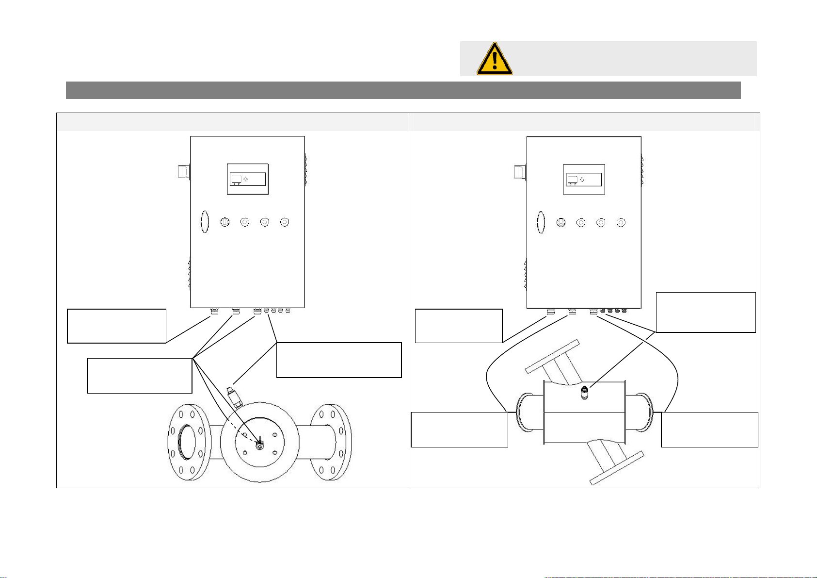
D.INSTALLATION OF THE REACTOR
Overall installation view
Reactor in a horizontal position Reactor in a vertical position
Marque, Modèles et Brevets déposés - Produits exclusifs
MP030_SN-GB.doc
Page 9
Copyright BIO-UV - 29/01/2009
LAMPS must be HORIZONTAL
Temperature
Sensor supply
General power
supply
UV lamps power
supplies
Temperature
Sensor supply
General power
supply
UV lamps power
supply
UV lamps power
supply

MP 030 EL NM GB Copyright BIO-UV - 29/01/2009
Marque, Modèles et Brevets déposés - Produits exclusifs
Page 10
Strictly follow the instructions:
Positioning of reactor Clearance zone (mm) required
to work on the reactor
- The water channel is horizontal.
- The UV lamps are horizontal.
- The purges are at the base of the reactor.
Lamps are in vertical position:
PROHIBITED
Marque, Modèles et Brevets déposés - Produits exclusifs
MP030_SN-GB.doc
Page 10
Copyright BIO-UV - 29/01/2009
200

THE REACTOR MUST BE PROPERLY CONNECTED TO
EARTH AS PER THE DIAGRAM BELOW
The earth wires marked and are supplied with the UV reactor.
The earth wire marked must be connected when the reactor is installed on site (6 mm² minimum
COMPULSORY)
Any earthing fault of the reactor will lead to an exclusion of the guarantee in
the event of electrolytic corrosion.
6 mm² minimum
6 mm² minimum
6 mm² minimum
Main switchboard
V cabinet
1
2
3
3
1
2

COMPULSORY INSTALLATION INSTRUCTIONS
It is preferable to install the UV reactor in By-Pass, and this must absolutely not be linked to pump
operation.
Instruction No. 1: The UV lamp must be HORIZONTAL whatever the position of the reactor.
Instruction No.2: The reactor must be correctly linked to the earth with a suitable wire of 6 mm²
minimum.
Instruction No.3: Fully observe instructions for the removal of lamps and quartz sleeves.
Instruction No.4: The UV sensor MUST be uppermost when the UV reactor is horizontal.
Instruction No.5: If the UV reactor is installed vertically, give preference to the input of water through
the bottom of the reactor and make sure that the purge valves are in the lower position.
Instruction No.6: Distance chemical products from the reactor to avoid any risk of corrosion.
UV REACTOR COMMISSIONING PROCEDURE
Action No.1: Fill the reactor with water and purge the air.
Check the absence of hydraulic leaks
Action No.2: Verify the correct operation of manual or automatic cleaning
Action No.3: Check the tightness of electrical terminal blocks and connectors
Action No.4: Calibrate the flowmeter
Action No.5: Turn on the lamps and check that they are working
Action No.6: Calibrate the UV sensor after a minimum of five minutes operation (UV lamp heating time)
Action No.7: Calibrate the 4-20 mA output (optional)
Action No.8: Test the correct operation of the flowmeter and the calibration carried out.
Action No.9: Fill in the maintenance sheet page 6
Reminder : If the UV lamps are turned off with the switch or the mains switch,
Wait 30 minutes befrore turning the UV lamps back on so as to not effect their
lifespan.
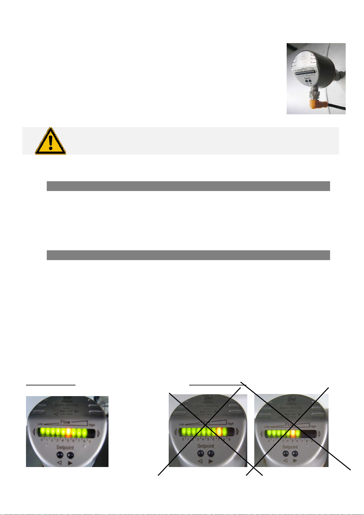
E. FLOW SENSOR
The flow sensor starts the unit when the flow is present and stops it when the flow rate
is insufficient in order to ensure sufficient time for lamp cooling.
The flow sensor is located on the reactor as on this picture:
At the start-up of reactor, it is NECESSARY to carry out a calibration on the basis of the
MINIMUM FLOW RATE in your installation..
Sensor setting to the minimum flow rate:
1. Provide power to the cabinet, lamp(s) off
2. Turn filtration on
3. Adjust filtration flow to the minimum (e.g.: By-Pass opening)
4. Press on the ►button of the flow sensor and hold it down.
5. The No.9 LED turns on and then flashes after approximately five seconds.
6. Release the button, calibration is finished ( lights 0 to 8 permanently on, No.9 flashes)
Setting the commutation threshold
To avoid to much stopping / starting of lamps due to fluctuations in flow, the
Commutation threshold (red LED) must not exceed No.5, if this is not the case:
1. Press briefly on ◄or ►, the red LED flashes
2. Press on ◄or ►as often as necessary to make LED 5 red
The system is now operational. Reset the flow rate to the maximum (close By-Pass).You can switch the
lamps on.
Stop filtration to check that the unit stops within a maximum time limit of approximately 60 seconds. (it
can only be turned back on can after a time delay of 30 minutes).
Correct setting: Incorrect settings:

F. MANUAL OF THE MONITOR BIO-UV MIII
(
)
Options according to the reactor
Marque, Modèles et Brevets déposés - Produits exclusifs
UV2000_NA-FR.doc
Page 14
Copyright BIO-UV - 29/01/2009
Activate/Deactivate
automatic cleaning
(
)
and
simultaneously
Main Display
Monitor
operating
indicator
R
On
F Flow
(
)
C Cleaning
(
)
Secondary display
L
EGEND
or
During 5s
o
r
During 5s
or
During 5s
Radiance V
management
(
)
Reset counter at
zero
Set power
regulation
(
)
Set cleaning
time cycle
(
)
During 5s
or
Set main alarm
threshold
S
et pre
-
alar
m
threshold
o
r
o
r
A1
A2
A3
B1
E1
G1
A
C
F
G
D
E
B

MP 030 EL NM GB Copyright BIO-UV - 29/01/2009
Marque, Modèles et Brevets déposés - Produits exclusifs
Page 15
GENERAL INFORMATION:
This operating manual describes all possible options,
Some of them aren’t available on your device according to your reactor type.
Definition of the 3 letters on the first display
R means that the reactor is switched on and operating.
F means that the water is flowing and that the flow is adequate in relation to the
setting that you made on the flowmeter.
C means that the automatic cleaning function is activated.
Note: for the reactors which don't have a flowmeter, the letter “F” stays always on the display.
●The screen is backlit: Just pressing on a key switches the back lighting on for one minute.
●Activation/deactivation of automatic cleaning: Pressing simultaneously on buttons A and B activates or
deactivates the automatic cleaning.
●Caution: if the cleaning is deactivated when the hydraulic cylinder is operating, the cleaning carriage may stop
in the middle of the reactor and block some of the UV rays.
ALERT MESSAGES:
The screen flashes when there is an alert message.
The alert messages are always shown on the secondary display and are independent of what is displayed on the
main display unit.
Display Meaning of the alert Solutions
This message appears when the
temperature of the cabinet exceeds 60°C.
The reactor is stopped automatically.
Check that the cabinet vents are not blocked.
Check that the fans are working properly.
This message appears when the
temperature of the reactor exceeds
44.5°C.
The lamps are stopped automatically.
Check that enough water is flowing through the
installation.
If there is a flowmeter, check that is correctly
calibrated.
This message appears when one or
several lamps are faulty.
The numbers show which of the lamps
are faulty.
Diagnose the cause of the breakdown.
This message appears when the
hydraulic cylinder on the automatic
cleaning is blocked. Diagnose the cause of the breakdown.
These 4 alert messages can be cleared by pressing on the key "OK".
It is preferable to carry out a maintenance operation before clearing the fault.
This message appears when the intensity
of the UVC radiation falls below the
pre-alarm threshold.
Check that the quartz sleeves are clean.
Check that the UV sensor is clean.
N.B.: when the lamps have been operating for a certain number of hours, this message appears naturally (normal wear of the lamps)
This message appears when intensity of
the UVC radiation falls below the main-
alarm threshold.
Check that the quartz sleeves are clean.
Check that the UV sensor is clean.
Chang the UV lamps.
This message appears when the lamps have been stopped (brought about by a safety
device). The lamps will not be relit until after a time delay of 30 minutes. This time delay is
to protect the lamps.
These 3 messages cannot be cleared unless the problem has been resolved.
MP 030 EL NM GB Copyright BIO-UV - 29/01/2009
Marque, Modèles et Brevets déposés - Produits exclusifs
Page 16
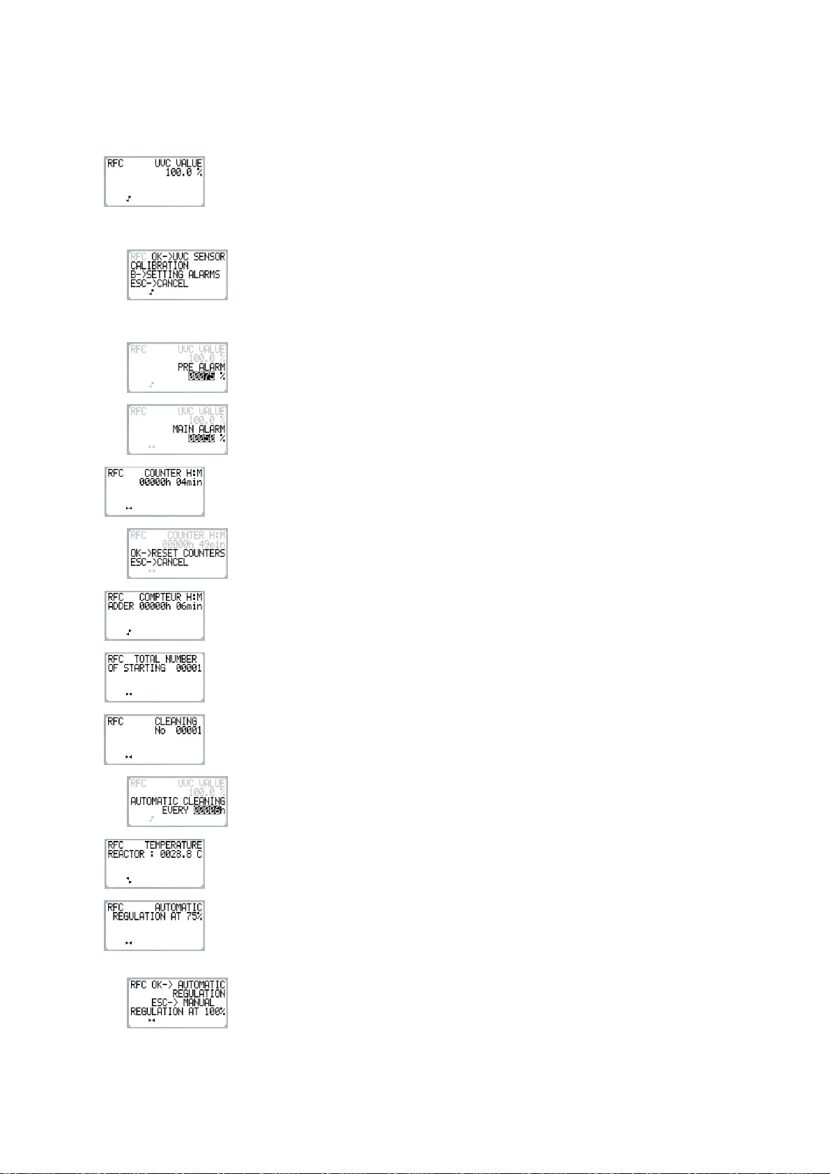
CONTENT OF MENUS AND SUB-MENUS:
Use the + or – keys to change from one menu to another.
Press on key A for 5 seconds to enter a menu.
When the word "OFF" is displayed, this means that the display option is not available on your device.
A
Display of UVC intensity measured by the sensor.
N.B.: each time the lamp is changed, you MUST calibrate the sensor even if the display
already shows 100%.
A1
Calibrating the sensor:
●It is important to carry out this operation when commissioning the reactor and also when
changing a lamp even if the display already shows 100%.
●It is important to wait 5 minutes before carrying out the calibration, to allow the lamps
to heat up.
●If your device is equipped with the power regulator, it is ESSENTIAL to switch over to
manual regulation (100%) before calibrating the sensor..
A2
Menu for adjusting the pre-alarm threshold. Set in the factory at 75%.
Allows you to set the UVC value at which the pre-alarm will trigger.
A3
Menu for adjusting the main alarm threshold. Set in the factory at 50%.
Allows you to set the UVC value at which the main alarm will trigger.
B
Display of lamp operating time. It is recommended to reset this counter at zero when you
change a lamp.
B1
Reset the hour counter and the number of lamp start-ups at zero.
C
Display the reactor's total operating time since commissioning. This counter cannot be reset at
zero..
D
Display of the number of lamp start-ups carried out. Resetting at zero is linked to that of the
hour counter.
E
Display of the total number of cleaning operations carried out since the reactor was
commissioned. This counter cannot be reset at zero.
E1
Adjustment of the frequency of the automatic cleaning cycle. Factory setting: one cleaning
cycle every 6 hours. Can be increased to a maximum of one cleaning cycle per hour.
F
Display of the reactor temperature.
G
Display of the type of power regulation used.
G1
Power regulation:
Allows you to set the type of power regulation of the UV lamps.
●On automatic regulation, the power switches automatically from 75% to 100% and back
depending on the reactor operating conditions.
●On automatic regulation, the lamps are always at 100% power.

MP 030 EL NM GB Copyright BIO-UV - 29/01/2009
Marque, Modèles et Brevets déposés - Produits exclusifs
Page 17
G.ALARM CONTACT (OPTION)
The pre-alarm and main-alarm faults are indicated by snap contacts on the monitor which are transmitted
to terminal strips (see the wiring diagram in order to identify them).
The snap contacts are normally closed. They open when respective alarms are active.
H.OPERATION OF THE 4-20MA OUTPUT (OPTION)
The 4-20mA adjustment must be realised:
- at the first installation of the reactor,
- at each calibrating of the UV sensor.
The 4-20mA adjustment must be realised only after the UV sensor calibration.
(See Chapter MANUAL OF THE MONITOR BIO-UV MIII)
The 4-20 mA output is the image of the UV-C sensor output not the image of the UV-C
% display on the monitor screen.
CALIBRATION OF THE 4-20MA OUTPUT:
1
Before the second step, you must realise the UV-C sensor calibration.
2
Turn the small screw clockwise
until the red LED lighting.
3
The 4-20mA output is calibrated at 100% of UV sensor.
Screw
Red
LED

MP 030 EL NM GB Copyright BIO-UV - 29/01/2009
Marque, Modèles et Brevets déposés - Produits exclusifs
Page 18
I. INSPECTIONS AND PREVENTIVE MAINTENANCE
In the event of work on the UV reactor, ensure that personnel are qualified and authorised.
RECOMMENDATIONS FOR VERIFYING OPERATION AND USE
The following points must be regularly checked in order to make sure that the UV reactor is operating
perfectly:
•Lamp operation check: Green light on
•UV intensity check: The display on the Millénium III monitor must show a value greater than
50%
In the event of a UV intensity fault (<50%); do not carry out the sensor calibration procedure
which must only be carried out with: new lamps(s), clean quartz, clean UV sensor
•Check the operation of the flowmeter: In the event of an interruption in flow (backwashing of
filters for example), the UV lamps must automatically turn off within 60 seconds, and restart 30
minutes after return to service. (See message on Millenium III display)
•Check the correct operation of electrical cabinet ventilators in order to avoid all risk of
overheating.
Check that the grills or filters are not obstructed.
•Activate the MANUAL cleaning device of the UV reactor on a daily basis
(Not applicable in the event of an automatic device: In this case make sure that the latter is
working)
•Checked the number of stop/starts of lamps on the Millénium III monitor display, which must be
coherent with the number and frequency of technical stoppages (filter backwashing, etc).

MP 030 EL NM GB Copyright BIO-UV - 29/01/2009
Marque, Modèles et Brevets déposés - Produits exclusifs
Page 19
RECOMMENDED INSPECTIONS AND PREVENTIVE MAINTENANCE
0 Changing UV lamps At the end of their life span:
-either display on the Millénium III monitor: UV
intensity <50%
-or combined chlorine rate in the basin
OPERATIONS ON EACH UV LAMP
CHANGEOVER AT LEAST ONCE
PER YEAR
Checking the general state of the UV
reactor
1 Replacement of quad ring seals Compulsory Compulsory
2 Checking the presence of quartz sheath
Teflon shims Compulsory
3 Cleaning or replacing the quartz sheath Compulsory
4 Replacing the cleaning wipers Recommended
5 Cleaning the UV sensor Compulsory Compulsory
6 Check the operation of the flowmeter Compulsory
7 Check the operation of ventilators:
- Cleaning grills
- Filter replacement (if applicable)
Recommended
Compulsory
8 UV sensor calibration Only new lamps, quartz sheath clean or new, UV
sensor cleaned
9 Pneumatic silencer replacement Only in the event of corrosion
10 Check the earthing of the reactor
11 Check the operation of the thermostat in the
electrical cabinet Recommended
12 Check the operation of the circuit breaker Recommended
13 Check tightening:
- Of terminal blocks in the cabinet
- Of connectors
- Of UV lamp connections
Recommended
MP 030 EL NM GB Copyright BIO-UV - 29/01/2009
Marque, Modèles et Brevets déposés - Produits exclusifs
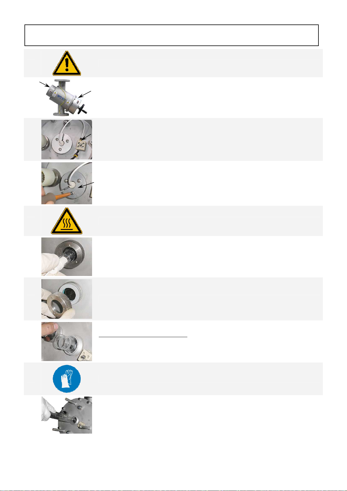
Page 20
1
SWITCH OFF the reactor, CUT the POWER source and EMPTY IT
2
Unscrew and remove the 2 covers.
3
Remove the wires from the lamp on both sides by unscrewing the terminals (only
the cables white supplying the lamp).
4
Unscrew the aluminium lamp base, 3 screws, on both sides.
5
Make sure that the UV lamp is cooled before handle it.
6
Take out the lamp together with its Teflon supports (if there are any) and place it
on a clean and soft surface.
Carry out this operation CAREFULLY taking care not to place your fingers
outside the cap.
7
Unscrew the MP nuts on both sides and remove the aluminium washer.
8
Gently remove the quartz sleeve:
●Push one end of the quartz sleeve in order to pull the other end.
●Remove the quartz sleeve and its seals.
9
Clean the quartz sleeve with acid or white vinegar or replace it if necessary.
10
While remaining in the axis, gently reposition the quartz sleeve in the direction
indicated by the label on the reactor.
CHANGING UV LAMPAND QUARTZ SLEEVE
Table of contents
Languages:
Other BIO UV Laboratory Equipment manuals


Popular Laboratory Equipment manuals by other brands

Oxford Instruments
Oxford Instruments PlasmalabSystem100 Installation data

Agilent Technologies
Agilent Technologies 6890 Series Service manual

seward
seward Stomacher 80 Biomaster user manual

ScanSpeed
ScanSpeed Mini instruction manual

Hamamatsu Photonics
Hamamatsu Photonics C12666MA manual

IKA
IKA MS 3 digital operating instructions


Thermo Scientific
Thermo Scientific IMH 60 operating instructions

RADWAG
RADWAG UYA 4Y PLUS Startup guide

Peak Scientific
Peak Scientific Genius SQ 24 user manual

Covaris
Covaris microTUBE-500 manual

Bayer HealthCare
Bayer HealthCare Clinitek Status Operator's manual

Thermo Electron
Thermo Electron HERAsafe KS Service instructions