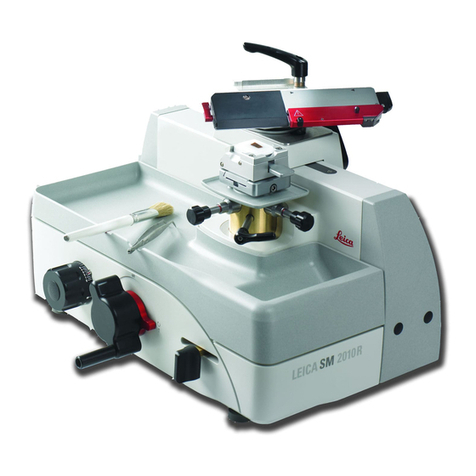
Leica BIOSYSTEMS SM2010 R User manual

Instructions for Use
Leica SM2010 R
Sliding Microtome
Instructions for Use
Leica SM2010 R, V 1.6 English – 10/2018
Order No.: 14 0508 80101 RevG
Always keep this manual with the instrument.
Read carefully before working with the instrument.


1
Leica SM2010 R
Leica Biosystems Nussloch GmbH
Heidelberger Str. 17 - 19
D –69226 Nussloch
Germany
Phone: +49 6224 143–0
Fax: +49 6224 143–268
Internet: http://www.LeicaBiosystems.com
Assembly contracted to Leica Microsystems Ltd. Shanghai
The information, numerical data, notes and value
judgments contained in this manual represent the
current state of scientific knowledge and state-of-
the-art technology as we understand it following
thorough investigation in this field.
We are under no obligation to update the present
manual periodically and on an ongoing basis ac-
cording to the latest technical developments, nor
to provide our customers with additional copies,
updates etc. of this manual.
To the extent permitted in accordance with the
national legal system as applicable in each indi-
vidual case, we shall not be held liable for errone-
ous statements, drawings, technical illustrations
etc. contained in this manual. In particular, no
liability whatsoever is accepted for any financial
loss or consequential damage caused by or
related to compliance with statements or other
information in this manual.
Statements, drawings, illustrations and other
information as regards contents or technical
details of the present Instructions for Use are not
to be considered as warranted characteristics of
our products.
These are determined only by the contract
provisions agreed between ourselves and our
customers.
Leica reserves the right to change technical spec-
ifications as well as manufacturing processes
without prior notice. Only in this way is it pos-
sible to continuously improve the technology and
manufacturing techniques used in our products.
This document is protected under copyright laws.
All copyrights to this documentation are held by
Leica Biosystems Nussloch GmbH.
Any reproduction of text and illustrations (or of
any parts thereof) by means of print, photocopy,
microfiche, web cam or other methods – includ-
ing any electronic systems and media – requires
express prior permission in writing by Leica Bio-
systems Nussloch GmbH.
For the instrument serial number and year of
manufacture, please refer to the name plate at
the rear of the instrument.
© Leica Biosystems Nussloch GmbH
NOTE

2Instructions for Use V 1.6 RevG – 10/2018
Table of contents
1. Important Information ............................................................................................................................. 3
2. Safety ......................................................................................................................................................... 4
2.1 Safety notes .................................................................................................................................................. 4
2.2 Warnings ....................................................................................................................................................... 4
3. Instrument Components and Specifications....................................................................................... 7
3.1 Overview - instrument components.......................................................................................................... 7
3.2 Technical data .............................................................................................................................................. 8
4. Instrument Setup.................................................................................................................................... 10
4.1 Standard delivery ....................................................................................................................................... 10
4.2 Site requirements....................................................................................................................................... 10
4.3 Unpacking.................................................................................................................................................... 11
4.4 Setup ............................................................................................................................................................ 11
4.5 Assembling the knife holder SN .............................................................................................................. 13
4.6 Assembling the blade holder SE.............................................................................................................. 16
5. Operation................................................................................................................................................. 21
5.1
Operating elements and their functions .............................................................................................................21
5.1.1 Section thickness setting.......................................................................................................................... 21
5.1.2 Coarse driving wheel................................................................................................................................. 21
5.1.3 Manual feed ................................................................................................................................................ 22
5.1.4 Automatic feed ........................................................................................................................................... 22
5.1.5 Directional fixture for specimen clamps ................................................................................................ 23
5.2 Clamping the specimen in the universal cassette clamp (UCC)......................................................... 24
5.3 Clamping a disposable blade ................................................................................................................... 25
5.4 Replacing the pressure plate ................................................................................................................... 26
5.5 Inserting the knife ...................................................................................................................................... 27
5.6 Sectioning.................................................................................................................................................... 28
5.7 Changing the specimen or interrupting sectioning .............................................................................. 29
6. Cleaning and maintenance .................................................................................................................. 30
6.1 Cleaning the instrument ............................................................................................................................ 30
7. Optional accessories ............................................................................................................................ 32
8. Troubleshooting ..................................................................................................................................... 39
8.1 Possible faults............................................................................................................................................. 39
8.2 Instrument malfunctions ........................................................................................................................... 39
9. Warranty and Service ........................................................................................................................... 40
10. Decontamination Confirmation ........................................................................................................... 41

3
Leica SM2010 R
Symbols in the text and their meanings
1. Important Information
(5)
Intended use of instrument
The SM2010 R is a manually operated sliding
microtome specifically designed for creating thin
sections of human tissue specimens of varying
hardness for histological medical diagnosis, e.g.
cancer diagnosis. It is intended for sectioning soft
and hard human specimens, as long as they are
suitable for being cut manually.
Any other use of the instrument is considered
improper!
Instrument type
All information provided in these Instructions for
Use applies only to the instrument type indicated
on the title page. A nameplate indicating the
instrument serial number is attached to the rear
side of the instrument.
Qualification of personnel
• The Leica SM2010 R may be operated by
trained laboratory personnel only.
Warnings
appear in a gray box and are marked by
a warning triangle .
Notes,
i.e. important user information appears
in a gray box and is marked by an infor-
mation symbol .
Numbers in parentheses refer to item
numbers in illustrations.
Manufacturer
This product fulfills the requirements
of the Council's Directive 98/79/EC
concerning in vitro diagnostics (IVD)
medical devices.
In vitro diagnostics (IVD) medical device
Observe the Instructions for Use
Order No.
Serial number
Date of Manufacture
• All laboratory personnel designated to operate
the Leica instrument must read these Instruc-
tions for Use carefully and must be familiar
with all technical features of the instrument
before attempting to operate it.

4Instructions for Use V 1.6 RevG – 10/2018
2. Safety
2.1 Safety notes
These Instructions for Use include important
information related to the operating safety and
maintenance of the instrument.
The instruction manual is an important part of
the product, which must be read carefully prior
to Instrument Setup and use and must always be
kept near the instrument.
To maintain this condition and ensure safe opera-
tion, the user must observe all notes and warnings
contained in these Instructions for Use.
2.2 Warnings
The safety devices installed in this instrument by the manufacturer only constitute the basis for
accident prevention. Primarily responsible for accident-free operation is above all the owner
of the instrument and, in addition, the designated personnel who operates, services or cleans
the instrument.
To ensure trouble-free operation of the instrument, make sure to comply with the following
instructions and warnings.
Be sure to comply with the safety instructions and warnings provided in this chapter.
Be sure to read these instructions, even if you are already familiar with the operation
and use of other Leica products.
These Instructions for Use must be ap-
propriately supplemented as required
by the existing regulations on accident
prevention and environmental safety in
the operator‘s country.
The current EC Declarations of Confor-
mity can be found on the Internet:
http://www.LeicaBiosystems.com
The protective devices on both instrument and accessories may neither be removed nor
modified. Only service personnel qualified by Leica may repair the instrument and ac-
cess the instrument’s internal components.

5
Leica SM2010 R
2. Safety
Warnings - Safety instructions / warning labels attached to the instrument
Warnings - Transport and installation
Warnings - Working at the instrument
Warnings - Cleaning and maintenance
• Safety notes on the instrument itself, which are marked with a warning triangle, indicate that
the correct operating instructions (as defined in these Instructions for Use) must be followed
when operating or replacing the item marked. Failure to adhere to these instructions may re-
sult in an accident, personal injury, damage to the instrument or accessory equipment.
• Once unpacked, the instrument may be transported only in an upright position.
• Before transporting the instrument, the knife sledge must be locked with the locking knob
(23, Fig. 2)!
• Do not transport the instrument by holding it by the knife sledge, coarse driving wheel or the
knob for setting the section thickness.
• Be very careful when handling microtome knives or blades. The cutting edge is extremely
sharp and can cause serious injuries!
• Always wear work safety shoes and safety gloves!
• Never place a knife anywhere with the cutting edge facing upwards and never try to catch a
falling knife! Always put the knives back into the knife case when not in use!
• Always clamp the specimen block BEFORE clamping the knife.
• Lock the knife sledge and cover the knife edge with the knife guard prior to any manipulation
of knife/blade or specimen, prior to changing the specimen block and during all work breaks.
• Always wear protective glasses and a mask when sectioning brittle specimens!
• Risk of splintering!
• Before each cleaning, remove the knife or disposable blade!
• Do not use solvents that contain acetone or xylene!
• Ensure that liquids do not enter the interior of the instrument during cleaning!
• When using cleaners, please comply with the safety instructions of the manufacturer and the
laboratory safety regulations!

6Instructions for Use V 1.6 RevG – 10/2018
2. Safety
2.3 Integrated safety devices The instrument is equipped with the
following safety devices:
• Knife guard (14) on the blade/knife
holder.
• Knife sledge locking knob (23) for
the knife sledge.
14
24
23
Knife guard on the blade holder
The blade holder is equipped with a tightly mounted knife
guard (14). This makes it possible to cover completely the
cutting edge of the blade (Fig. 3).
Knife sledge locking knob
The knife sledge is locked in place us-
ing the locking knob (23) that engages
in the notch points on the bar (24), thus
holding the knife sledge securely. The
bar has 11 notch points, with a dis-
tance of 10 mm between each.
14
14
11
Knife guard on the knife holder
Knife guard on the blade holder
Knife sledge
locked
Knife sledge
is movable
Prior to any manipulation
of the knife or specimen, or
each change of specimen,
and during breaks, always
cover the cutting edge of
the blade/knife with the
knife guard (14)!
Caution!
When the knife guard is
pushed over the blade, do
not reach into the blade
from below!
Prior to changing the speci-
men or knife and before
transporting the instrument,
lock the knife sledge (11)
using the locking knob (23).
Fig. 3
Fig. 2

7
Leica SM2010 R
3. Instrument Components and Specifications
Specimen cylinder
Removable
section waste tray
3.1 Overview - instrument components
Knife sledge
Ergo handle for
moving the knife
sledge
Blade holder SE
Coarse driving
wheel
Adjusting knob of
automatic feed
Knife guard on
the blade holder
Fig. 4
Magnetic
knife sledge
immobilizer
Setscrew for
orientation in cutting
direction
Adjustable
instrument feet
HN40
tensioning clamp
Lever for
clamping the
blade
Scaled adjusting knob
for setting the section
thickness
Lever for manual feed
Clamping lever for
lateral displacement
Clamping lever for
specimen orientation
Knife sledge
lock
Clearance angle
scale
Knife holder SN
Setscrew for
orientation
perpendicular to
cutting direction
Universal
cassettes
clamp
Quick clamping
system for holding
the specimen
clamps
Knife guard on
the knife holder

8Instructions for Use V 1.6 RevG – 10/2018
3. Instrument components and specifications
3.2 Technical data
General
Approvals: The instrument-specific marks are located on the
name plate.
Operating temperature range: 10 °C to +40 °C
Relative humidity: max. 80% non-condensing
Operating temperature range during storage:
+ 5 °C to +55 °C
Storage humidity: < 80 %
Microtome
Section thickness range: 0.5 - 60.0 µm
Section thickness settings: from 0.5 - 5.0 µm in 0.5 µm increments
from 5.0 - 10.0 µm in 1.0 µm increments
from 10.0 - 20.0 µm in 2.0 µm increments
from 20.0 - 60.0 µm in 5.0 µm increments
Automatic specimen feed: from 0 to 30 µm
Total specimen stroke: approx. 50 mm
Clearance angle adjustment: –3° to 10°
Maximum specimen size: 50 x 60 x 40 mm
Specimen orientation
in cutting direction: ± 8°
perpendicular to cutting direction: ± 8°
Declination: 0° - 45° in cutting direction
Dimensions and weight
Width (with coarse driving wheel
and Ergo handle): 390 mm
Width (base plate): 256 mm
Depth: 430 mm
Height (total): 343 mm (with blade holder)
Working height (knife blade): 255 mm (measured from the table)
Weight (without accessories): Approx. 20 kg

9
Leica SM2010 R
3. Instrument Components and Specifications
3.3 Instrument specifications
• The Leica SM2010 R is a manually operated sliding microtome, designed
as a low-maintenance tabletop instrument with roller-guided knife
sledges and automatic section thickness feed.
• Stable, torsion-free basic design with micrometer feed system in a closed
housing, protected from ingress of paraffin waste.
• The vertical cross roller bearings have a cover which provides reliable
protection from ingress of section waste.
• The instrument has an ergonomically optimized specimen head position;
the smooth-running knife sledge can be securely locked in 10 mm incre-
ments.
• Precise 8° XY orientation with defined zero position.
• Individually adjustable Ergo handle for easily moving the sledge.
• The sectioning window can be adjusted to the specimen size.
• The cutting thickness can be adjusted within the range of 0.5 µm to 60 µm;
the automatic feed functions in the range of 0.5 µm to 30 µm.
• Manual feed by pulling or pushing the feed lever.
• Depending on the version, the instrument is either fitted with a blade
holder SE for disposable blades or a knife holder SN for conventional
knives. The blade holder and knife holder each have an integrated knife
guard. In the knife holder SN a blade rail can also be inserted for holding
disposable blades.
• The knife or disposable blade holder does not need to be removed for
the clearance angle adjustment.
• The smooth-turning, coarse driving wheel can be chosen with clockwise
or counterclockwise rotation.
• Different specimen clamps can be inserted in the quick clamping system.
• The instrument has an antistatic waste tray for holding a large volume.

10 Instructions for Use V 1.6 RevG – 10/2018
4. Instrument Setup
4.2 Site requirements
• Stable, vibration-free laboratory table with horizontal, flat table top, as
far as possible vibration-free ground.
• No other instruments nearby which might cause vibrations.
• Room temperature consistently between + 10°C and + 40 °C.
• Free access to coarse driving wheel and knife sledge.
• The instrument is suitable for operation in enclosed rooms only.
4.1 Standard delivery
The Leica SM2010 R standard delivery includes:
1 Leica SM2010 R basic instrument.............................................. 14 0508 42258
1 section waste tray........................................................................ 14 0508 42328
1 tool set consisting of.................................................................... 14 0508 42983
1 Allen key size 6.............................................................................. 14 0194 43634
1 Allen key with handle, size 4....................................................... 14 0194 04782
1 Allen key T 25 ................................................................................ 14 0194 45250
1 open-end wrench, size 10........................................................... 14 0330 04158
1 spare magnet ................................................................................ 14 0508 44762
1 dust protection cover................................................................... 14 0212 18961
1 pair of safety gloves, size S ........................................................ 14 0340 40859
1 Instructions for Use (printed English
with language CD 14 0508 80200).................................................. 14 0508 80001
The accessories ordered are included in a separate box.
Carefully check the delivery against the packing list and the deliv-
ery note. Should you find any discrepancies, please contact your
Leica sales office without delay.

11
Leica SM2010 R
4.3 Unpacking
• To lift the instrument from the box, hold it on
the left and right of the housing (Fig. 5), lift it
out of the foam cushion of the package and
place it on a stable lab table.
• Remove all adhesive tape used as transport
anchors.
4.4 Setup
Loosening the transport locking screw of the
knife sledge
23
11
12
Fig. 6
4. Instrument Setup
First check the shipment for external damages upon arrival.
If it is evident that the shipment was damaged during transport,
please make a claim to the carrier immediately.
• Open the packaging.
• Remove all foam material.
• Take out all accessories and the instruction manual.
Do not transport the instrument by hold-
ing it by moving parts, on the knife
sledge, coarse driving wheel or the
knob for setting the section thickness.
Fig. 5
The locking knob (23) secures the knife
sledge during transport.
In daily operation, it is also used to lock
the knife sledge in place.

12 Instructions for Use V 1.6 RevG – 10/2018
4. Instrument Setup
25
26
Horizontal alignment
For safe and accurate work, it is important that
all instrument feet are in uniform contact with the
installation surfaces.
The microtome is horizontally aligned at the fac-
tory. If a completely level or horizontal surface is
not available at the installation site, the instrument
must be realigned.
To do so, the two instrument feet (25) on the right
side of the instrument are height-adjustable.
• For alignment, loosen the locknuts (26) using
a size 10 open-end wrench.
• Adjust the instrument feet (25) until the micro-
tome is in a stable position at the installation
location according to requirements.
• Retighten the locknuts.
Setting the Ergo handle
The Ergo handle (12), which is used to move the
knife sledge, can be set individually to an ergo-
nomic gripping position.
• To do this, loosen the fastening screw (10)
using a size 6 Allen key (28).
• Turn the handle (12) to the desired position
and retighten the screw (10).
12
28
10
Fig. 7
Fig. 8

13
Leica SM2010 R
4.5 Assembling the knife holder SN
• Lock the knife sledge (11) in place using the
locking knob (23) so that it cannot be moved.
• The intermediate plate (60) intended for the
knife holder SN, is mounted on the mounting
table (62) of the knife sledge (11).
Installing the intermediate plate
• As shown in Fig. 9, place the intermediate plate
on the mounting table. Make sure that the two
index markings (65) are at the top and point
towards the back.
• Insert the five countersunk screws (61.1–61.5)
into the bores and tighten them crosswise (in
the sequence shown in Fig. 10) using an Allen
key T25 (63).
23
23
60
62
65
64.1
63
61.3
61.5
61.1
61.2
61.4
64.2
11
4. Instrument Setup
Fig. 9
Important!
The mounting table must be absolutely
clean and dry. There must not be any
foreign particles on it. Otherwise, sec-
tions could become contaminated.
Fig. 10

14 Instructions for Use V 1.6 RevG – 10/2018
Fastening the knife holder
• Press the clamping lever (66) of
the knife holder (67) downwards
and screw the bottom of the
thread (66.1) into one of the two
bores (64.1) or (64.2, Fig. 11) of the
intermediate plate (60).
66
66.1
64.1
64.2 60
67
66
Assembling the knife holder SN (continued)
4. Instrument Setup
• Continue turning the clamping
lever (66) in a clockwise direc-
tion until the knife holder is firmly
screwed on (Fig. 12).
67
60
The clamping lever (66)
has a plastic handle that
can be turned into what-
ever position is best. To
do so, pull the handle up-
wards and turn it into the
desired position (Fig. 12).
It will then lock automati-
cally when released.
The knife holder SN (67)
has two bores (64) and
thus two different mount-
ing positions for different
sectioning requirements.
Fig. 11
Fig. 12

15
Leica SM2010 R
Fig. 13
Setting the clearance angle (Fig. 13)
• Unscrew the knurled head screw (69).
• Set the required angle with the adjusting lever
(70) using the scale for the clearance angle
(71). The upper edge (73, red arrow in Fig. 13)
of the lever (70) has to align with the index
mark of the selected degree value.
• To fix the setting in place, retighten the knurled
screw (69).
The clearance angle can also be adjusted if a
knife is clamped.
• To do this, slightly unscrew the two clamping
screws for the knife (72) and, if necessary, also
the knurled head screw (69).
• Set the desired angle as described above.
• To fix the setting in place, retighten the knurled
screw (69).
Enlarged detail:
Scale for
setting the
clearance
angle.
72
69
70
73
4. Instrument Setup
Inclination (declination)
of the knife holder SN
• Loosen the clamping lever (66).
• Set the required declination (inclination of the
knife holder from the cutting direction) on the
scale (55.1) at the back of the knife holder (67).
• On the intermediate plate (60) there is an index
mark (68.2) which serves as a point of refer-
ence for the scale division when adjusting the
declination.
• For fixation, tighten the clamping lever (66)
firmly in the required position.
66
67
60
68.1
68.2
Fig. 14
Assembling the knife holder SN (continued)
71
70

16 Instructions for Use V 1.6 RevG – 10/2018
4.6 Assembling the blade holder SE
4. Instrument Setup
Mounting the grooved plate
• Lock the knife sledge (11) in place using the
locking knob (23) so that it cannot be moved.
• The grooved plate (50), which is intended for
the blade holder SE, is mounted on the mount-
ing table (62) of the knife sledge (11).
23
50
62
65
11
• As shown in Fig. 15, place the grooved plate on
the mounting table. Make sure that the groove
(54) for inserting the blade holder has the
rounded opening (56) for the T-piece (Fig. 16)
pointing forward.
• Insert the six countersunk screws (61.1–61.6)
into the bores and tighten them crosswise (in
the sequence shown in Fig. 16) using an Allen
key T 25 (63).
23
63
61.3
61.5
61.1
61.2 61.4
61.6
56
The blade holder SE is designed for conventional
disposable blades from all common manufactur-
ers.
It is available in two models: one for low-profile
blades and one for high-profile blades.
The blade holder SE has a lateral movement, so
that the entire width of the blade can be used.
54
54
Important!
The mounting table must be absolutely
clean and dry. There must not be any
foreign particles on it. Otherwise, sec-
tions could become contaminated.
Fig. 15
Fig. 16

17
Leica SM2010 R
4. Instrument Setup
Inserting the blade holder SE
• Push the blade holder fully to the back such
that the T-piece can be inserted in the round
insertion opening (56).
• Then turn the blade holder (9) approx. 90°
(Fig. 18), insert the stopper (18) that closes the
insertion opening (56), and tighten it using the
Allen key T25 (63).
• To clamp the blade holder on the grooved
plate, tighten the screw (52) on the back of the
blade holder base (17) using a size 6 Allen key
(Fig. 19).
Fig. 17
Fig. 18
18
54
• Mount the blade holder (9) on the grooved
plate (50) such that the T-piece (53) on the
underside is inserted in the groove (54).
56
9
52
63
The stopper (18)
serves for clos-
ing the insertion
opening (56) for
the T-piece in the
grooved plate, in
order that no sec-
tion waste can ac-
cumulate there.
53
Assembling the blade holder SE (continued)
1.
2.
3.

18 Instructions for Use V 1.6 RevG – 10/2018
4. Instrument Setup
Inclination (declination)
of the blade holder SE
• Unscrew the Allen screw (52) at the back of the
blade-holder base using an Allen key SW 6.
• Turn the blade holder to the required position.
• Set the required declination (inclination of the
blade holder to the cutting direction) on the
scale (55.1) at the back of the blade holder (67).
• On the grooved plate (60) there is an index
mark (55.2) which serves as a point of refer-
ence for the scale division when adjusting the
declination.
• For fixation, tighten the screw (52) firmly in the
required position.
Fig. 19
52
55.2
55.1
Assembling the blade holder SE (continued)
19
27
27.1
Lateral movement
The lateral displacement feature enables the en-
tire cutting length of the blade to be used without
having to readjust the blade holder.
• To move the blade rail, turn the clamping lever
of the lateral displacement mechanism (19) on
the segment arc to the right into the "open"
position.
• Now the blade runner (20) can be moved later-
ally. To clamp, turn the lever (19) back to the
left.
The two triangular marks (27) indicate the area
in which the blade rail can be moved laterally,
relative to the circular mark (27.1).
Fig. 20
Table of contents
Other Leica BIOSYSTEMS Laboratory Equipment manuals

Leica BIOSYSTEMS
Leica BIOSYSTEMS HistoCore BIOCUT User manual

Leica BIOSYSTEMS
Leica BIOSYSTEMS HistoCore PEARL User manual

Leica BIOSYSTEMS
Leica BIOSYSTEMS Aperio AT2 DX User manual

Leica BIOSYSTEMS
Leica BIOSYSTEMS Aperio GT 450 User manual

Leica BIOSYSTEMS
Leica BIOSYSTEMS Aperio GT 450 Service manual

Leica BIOSYSTEMS
Leica BIOSYSTEMS SM2010R User manual

Leica BIOSYSTEMS
Leica BIOSYSTEMS ASP300S User manual

Leica BIOSYSTEMS
Leica BIOSYSTEMS HistoCore SPECTRA CV User manual

Leica BIOSYSTEMS
Leica BIOSYSTEMS VT1000 S User manual