Northern Brewer The Center of Gravity User manual
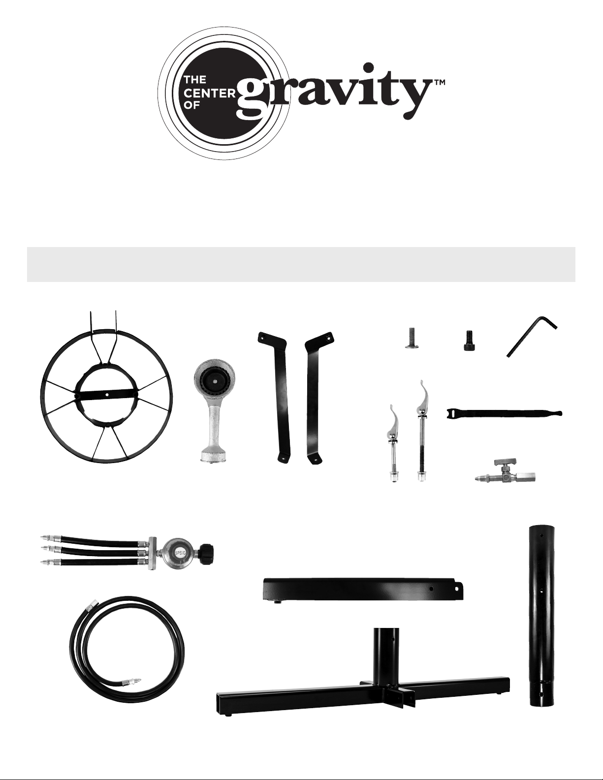
INVENTORY
A revolutionary, pro-quality brew sculpture in a powerful, compact package—at a compact price.
The Center of Gravity™ is built to brew right out of the box. Virtually tool-free setup. A tiny total
footprint of just one square meter. Quick, compact storage. Center of Gravity™ is the first all-in-
one brew sculpture that you can set up in 15 minutes and break down to fit in a hockey bag.
ADDITIONAL EQUIPMENT REQUIRED: Crescent Wrench
BASE
LEGS (2)
POSTS (3)
PROPANE LINES (3)
3-WAY PROPANE MANIFOLD
NEEDLE VALVES (3)
ADJUSTABLE
FEET (4) HEX-HEAD
SCREWS (6) ALLEN WRENCH
VELCRO STRAPS (10)
QUICK CLAMPS
SMALL (4)
LARGE (7)
SMALL PARTS
BASE
BURNERS (3)BURNER FRAME (3) FRAME SUPPORTS (6)
RIGHT (3)
LEFT (3)
BURNERS
PROPANE LINES

TECHNICAL DETAILS
– Do not leave this system unattended while any burner is lit or
while heating.
– Monitor the system when hot and after use (temperatures
above 100°F/38°C). Heated liquid and equipment can remain at
scalding temperatures long after the boil has ended and burners
have been shut off.
– Do not exceed 125 lbs. per burner assembly or 300 lbs. for the
full system.
–Do not use this system for heating oil or grease.
– Keep children, pets and unauthorized persons away from the
Center of Gravity™ at all times.
– Always operate the system on a level, stable, noncombustible
surface such as brick or concrete. Surfaces not suitable for use
include wood, asphalt or plastic which may burn, blister or melt.
– This system is for outdoor use only. Do not use in a building,
garage, tent or any other enclosed area. Do not use in or on a
recreational vehicle or boat.
– Do not locate this system under any overhead construction.
Keep a minimum clearance of 10 ft. (3.05m) from the sides,
front and back of the burner to any construction. Keep the area
clear of any combustible material. Do not use on or under any
apartment or condo balcony or deck.
– Do not allow the flame to roll past the bottom of the brew kettle.
–Do not install casters or wheels on the Center of Gravity™.
– Never lift or move a full kettle of water onto or off of the Center
of Gravity™.
– Only use the propane tank valve as the gas shutoff. Do not use
the regulator or needle valves.
– A 20-pound (9 kg) propane cylinder should be used with this
burner. The LP-gas supply cylinder used must have a protective
collar and must be constructed and marked in accordance with
the specifications for LP-gas cylinders of the U.S. Department
of Transportation (DOT), cylinders, spheres and tubes for the
transportation of Dangerous Goods. Do not store a spare LP-gas
cylinder indoors, or under or near the Center of Gravity™. Never
fill the cylinder beyond 80% full. For proper vapor withdrawal,
the 20 lb. (9 kg) cylinder should be used in the proper upright
position. Cylinder must be turned off while not in use. Failure
to follow these instructions and warnings could result in fire or
explosion which could cause property damage, personal injury
or death.
– Keep the gas supply hose away from heated surfaces at all times.
–Ensure all connections are tightly secured before each use.
–Level the stand with the adjustable feet prior to each use.
– Check for gas leaks before each use—this can be done by
applying soapy water and looking for bubbles.
– This system gets dangerously hot while in use. Use well-
insulated protective gloves, clothing and boots during operation
for protection from hot surfaces or splatter from hot liquids.
Safety goggles are also recommended to protect you from
splatter.
– Keep a fire extinguisher nearby at all times when operating the
Center of Gravity™.
– Use a pump or gravity to move hot liquids from or into each
brewing vessel.
–Allow the system to cool to 100°F (38°C) before moving or storing.
Product Center of Gravity™ Maximum Batch Size 10 Gallons
Burner Output 54,000 BTUs Load Capacity (One Burner) 125 lbs.
Weight 90 lbs. Load Capacity (Full System) 300 lbs.
Footprint 38” x 38” Maximum Kettle Diameter 16.5”
Height of Bottom Burner 26.5” Maximum Kettle Height 19”
Height of Middle Burner 44.75” Base Material Powder-Coated Steel
Height of Top Burner 63” Burner Frame Material High-Temp-Industrial-Paint-Coated Steel
Full Height 63.5” Burner Material Cast Iron
Packs into Hockey Bag 35”L x 17”W x 18”H Propane Line Material Rubber with Brass Connections
WARNING
READ AND UNDERSTAND BEFORE USING THIS PRODUCT
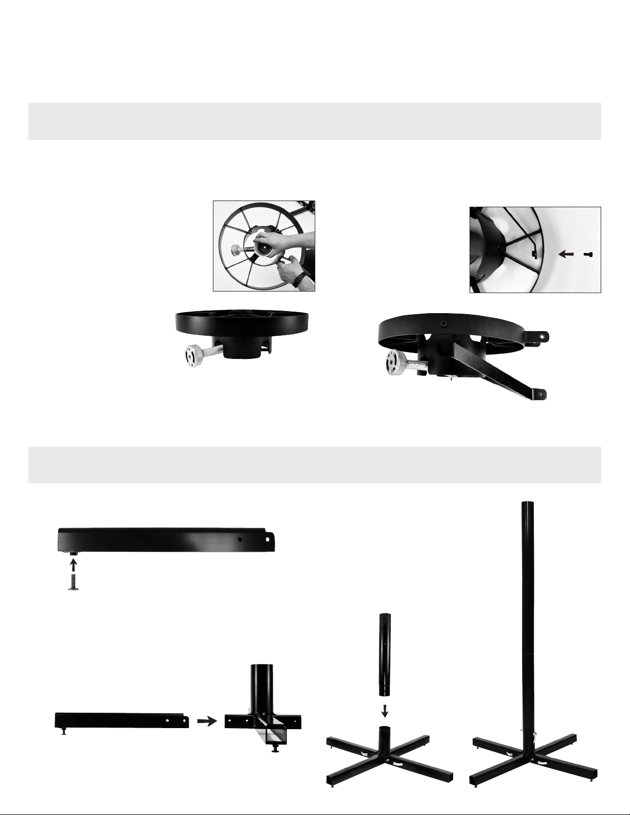
BUILDING THE BASE
EQUIPMENT: Base, Adjustable Feet, Legs, Small Quick Clamps, Assembled Base, Center Posts, One Large Quick Clamp
CREATING THE BURNER ASSEMBLIES
EQUIPMENT: Burners, Burner Frames, Burner Supports, Hex-Head Screws
ASSEMBLY
BEFORE YOU BEGIN
Check your inventory. Ensure you’ve received everything listed in the Inventory section.
You can also follow along online with a how-to video for assembling the Center of Gravity™.
1. Position the burner frame face-up.
2. Remove the nut and washer from the screw at the
base of the burner.
FULLY ASSEMBLED
RIGHT-ORIENTED BURNER
3. Holding the head of the burner, slide
the air inlet down through the center
of the frame. You will create two
right-oriented burners and one left-
oriented burner.
5. For the left-oriented burner, position the air inlet tube through
the left notch in the frame. Use the right notch for the right-
oriented burners.
6. Flip the burner over, holding it together as you flip it.
7. Thread the washer and nut onto the burner screw.
Tighten with a wrench.
8. Locate the holes on the
rim of the burner frame.
Use a hex head screw to
attach each support to
the inside of the frame.
4. Insert the burner screw
through the hole in the
center bar on the burner
frame.
LEFT-ORIENTED BURNER
1. Thread one foot into each of the four legs.
2. Slide the non-footed end of the weldless leg over the bracket
on the base. Using two small quick clamps, secure each leg
to the base.
3. Insert post, tapered end first, into the
base. Secure with a large quick clamp.
4. Insert the two remaining posts. Do not
secure with quick clamps—this will be
done when the burner assemblies are
installed.
STEP 3
FULLY
ASSEMBLED
BASE
STEP 1
STEP 2
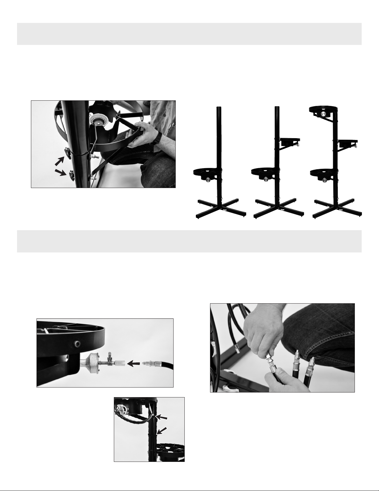
INSTALLING THE BURNER ASSEMBLIES
EQUIPMENT: Two Right-Oriented Burner Assemblies, One Left-Oriented Burner Assembly, Six Large Quick Clamps, Allen Wrench
INSTALLING THE PROPANE LINES
EQUIPMENT: Needle Valves, Propane Hoses, Propane Manifold, Velcro Straps, Crescent Wrench (not included)
1. Attach the bottom (right-oriented) burner. Undo the nut of
two quick clamps. Insert the first clamp through the burner
support and the lowest holes on the center post, then secure.
Use the second clamp to attach the mounting bracket to the
center post.
2. From the opposite direction as the first burner, secure the
middle (left-oriented) burner assembly to the center post.
STEP 1
3. From the same direction as the bottom burner, secure the
remaining right-oriented burner assembly to the center post.
4. Ensure the center post is straight and there is no wobble in the
legs. Adjust the feet on the base to straighten as necessary.
Ensure burner frames are level, then tighten the hex head
screws with the allen wrench.
STEP 1 STEP 2 STEP 3
1. Install the needle valves. Thread a needle valve into the air
inlet tube on each burner. DO NOT OVERTIGHTEN. The brass tip
of the needle valve is soft and can snap off if overtightened.
Hand-tighten only.
2. Attach the first propane hose. Thread the first hose into the
needle valve of the top burner. Tighten with a wrench.
3. Run the propane hose along
the front-facing burner
support. Secure it to the
support with one velcro strap.
There should be as little slack
as possible without kinking
the hose. Attach two velcro
straps together and secure the
hose to the center post.
4. Repeat Step 2 and 3 for the middle hose.
5. Attach the bottom hose as described in Step 2. Use the final double
velcro strap to secure all three propane hoses to the bottom of the
center post.
6. Install the manifold. Thread each propane hose into the
manifold and tighten with a wrench.
STEP 2
STEP 3
STEP 6
NOW YOU’RE READY TO BREW!
Popular Brewing System manuals by other brands


Spike
Spike Flow user guide

Curtis
Curtis Gem-230A instructions

Blichmann Engineering
Blichmann Engineering 7 BBL Assembly operation maintenance

Blichmann Engineering
Blichmann Engineering 2 BBL Hybrid Brewhouse Assembly operation maintenance
 OPERATING PRINCIPLE")
BRAVILOR BONAMAT
BRAVILOR BONAMAT FRESHONE (G) OPERATING PRINCIPLE

Fetco
Fetco TBS-2121XTS user guide

Tribest
Tribest RAW TEA KETTLE Operation manual

Sprowt Labs
Sprowt Labs Acro user manual

Fetco
Fetco Touchscreen 1.0 CBS-2131XTS Users guide and operator instructions

Curtis
Curtis D500GT12A000 user guide

Ruby Street Brewing
Ruby Street Brewing Alpha Ruby owner's manual

WILLIAMSWARN
WILLIAMSWARN BrewKeg25 user guide