Northern Computers KP-13 Service manual

Specificationssubjecttochange
TECHNICTECHNIC
TECHNICTECHNIC
TECHNICAL BULLETINAL BULLETIN
AL BULLETINAL BULLETIN
AL BULLETIN
Headquarters:
5007S.HowellAve.
Milwaukee, WI 53207 USA
Tel:+1(414)769-5980
Fax:+1(414)769-5989
or+1(414)769-5996(Int’l)
Northern Computers, Inc.
Worldwide Locations:
• Crawley,Sussex,UnitedKingdom
Tel:(44)1293-592700•Fax: (44) 1293-523061
• SaoPaulo,Brazil
Tel:(55) (11)826-4944•Fax:(55)(11)826-0649
• Australia
Tel: (612)9699-3700 Fax: (612)9699-3101
• Hong Kong
Tel: 852-2528-1897 • Fax:852-25284599
• Montreal,Quebec,Canada
Tel: 514-933-3363 • Fax:514-933-3447
• Moscow,Russia
Tel: (7) 095-723 2626•Fax:(7)095-9565428
• France
Tel: 33-1-30-13-03-93 Fax: 33-1-3-13-03-90
• Mexico
Tel: (52) (5) 280-7890 Fax: (52)(5)280-8555
• Ecuador
Tel: (593) (2) 265-588/91 Fax: (593)(2)461-379
July 1998; Rev. 2.1 (page 1 of 2)
KP-13 Keypad Wiring Instructions
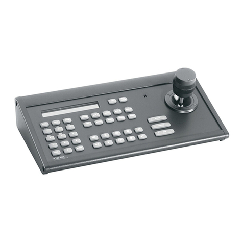
The KP-13 Keypad is a 5-wire Wiegand output keypad suitable for outdoor use. It is wired to a control
panel in the same manner as a card reader (see figure 1). The KP-13-ILL is the same keypad with illumina-
tion.
The KP-13 uses the 32-bit Wiegand format: _F=pn_2_32_S_0_D_0_B1_B2_B3_B4 (required for N-1000
with 4.17 or older firmware).
This format can be entered in a text file or Terminal Mode (not required for N-500). Refer to panel installa-
tion and programming manuals for more information. As with all keypads, press the “#” key after code
entry. To clear an entry, press the “*” key. To toggle illumination off and on (KP-13-ILL only), press “*” and
“3” at the same time.
LED Operation. When the reader is first powered up, the green LED will remain on until after the first
valid card read. When the “M” option is enabled in the panel programming the LEDs operate as follows:
●Normally, the red LED is on.
●Upon valid code entry, the green LED comes on and the red LED goes off.
●After the LED pulse time elapses, the green LED goes off and the red LED comes on.
●Uponinvalidcodeentry,no LED changeoccurs.
Grounding. The tan wire is a chassis ground. If the keypad is mounted directly on grounded metal, tie the
tan wire to the grounded metal. Tie the keypad cable shield to the control panel ground point and float
shield at keypad. If the keypad is mounted on ungrounded metal or nonmetallic material, tie the tan wire to
the keypad cable shield and connect the shield to the control panel ground point.
Wiring specifications NCI Part # Description Maximum Distance
NC1861/BL 6-wire 18 AWG shielded 500 feet
TD2006
Figure 1. Wiring for the KP-13.
Power for the keypad can be
supplied from the control panel.
KP-13
Black (Common)
Red (+5VDC)
Green (Data 0)
White (Data 1)
Brown
Tan
(Earth Ground)
The Blue wire remains disconnected (not used)
(LED)

Specificationssubjecttochange
TECHNICTECHNIC
TECHNICTECHNIC
TECHNICAL BULLETINAL BULLETIN
AL BULLETINAL BULLETIN
AL BULLETIN
Headquarters:
5007S.HowellAve.
Milwaukee, WI 53207 USA
Tel:+1(414)769-5980
Fax:+1(414)769-5989
or+1(414)769-5996(Int’l)
Northern Computers, Inc.
Worldwide Locations:
• Crawley,Sussex,UnitedKingdom
Tel:(44)1293-592700•Fax: (44) 1293-523061
• SaoPaulo,Brazil
Tel:(55) (11)826-4944•Fax:(55)(11)826-0649
• Australia
Tel: (612)9699-3700 Fax: (612)9699-3101
• Hong Kong
Tel: 852-2528-1897 • Fax:852-25284599
• Montreal,Quebec,Canada
Tel: 514-933-3363 • Fax:514-933-3447
• Moscow,Russia
Tel: (7) 095-723 2626•Fax:(7)095-9565428
• France
Tel: 33-1-30-13-03-93 Fax: 33-1-3-13-03-90
• Mexico
Tel: (52) (5) 280-7890 Fax: (52)(5)280-8555
• Ecuador
Tel: (593) (2) 265-588/91 Fax: (593)(2)461-379
July 1998; Rev. 2.1 (page 2 of 2)
TD2006
KP-13-ILL
+
–
5 VDC
Power Supply
Black (Common)
Green (Data 0)
White (Data 1)
Brown
The Blue wires remain disconnected (not used)
(LED)
Red (+5 VDC)
Tan
(Earth Ground)
Brown (LED)
Green (Data 0)
White (Data 1)
Red
The Blue wires remain disconnected (not used)
(+5 VDC)
Black (Common)
Tan
(Earth Ground)
KP-13-ILL
Figure 2. Wiring for the
KP-13. When more than
one illuminated keypad is
used, at least one must be
connected to a separate 5
VDC power supply.
Northernrecommends
that BOTH be connected
to the separate power
supply as shown here.
Power Supply. The KP-13 power can be supplied from the control panel. However, if more than one
illuminated keypad is used, then a separate 5 VDC power supply may be required. (See figure 2.) Choose
power source to match correct power consumption.
KP-13 KEYPAD WIRE TERMINATIONS
Wire Color Function N-1000-II N-1000-III N-1000-IV
Brown LED TB5-1 TB5-1 4 reader board LED
White Data 1 TB5-2 TB5-2 4 reader board Data 1
Green Data 0 TB5-3 TB5-3 4 reader board Data 0
Red +5VDC TB5-4 or external +5VDC 4 reader board +5VDC
Power Source Power Source Power Source or Ext. Power Source
Black CommonGround TB5-5&External TB5-5&Ext. 4 reader board Gnd &
Power Supply - Power Supply - Ext. Power Supply -
Power Consumption 5 VDC mA
notilluminated 80 mA
illuminated 150 mA
Panel Reader Current Max.
N-1000-II 250 mA
N-1000-III/IV 500 mA
N-500 300 mA
N-750 2.5 Amps
