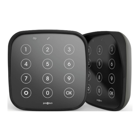
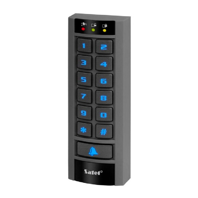
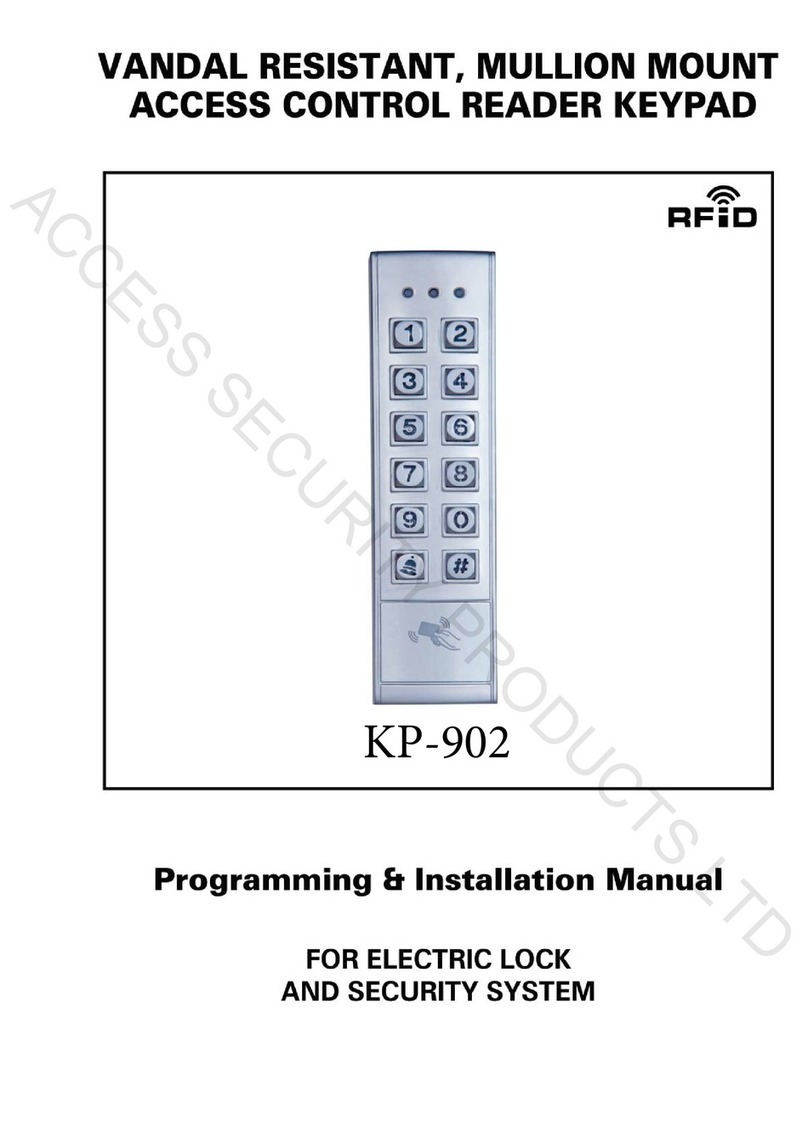
Tekno K1 User manual

Page 1
Standalone Wired Keypad with RFID and App Control
Automation Systems
Australia
Power: 12V DC
Standby Current: ≤35 mA
Operating Current: ≤100 mA
Maximum Users: 10,000 Users in Standalone Mode
Operating Temperature: -40°C to +60°C
Operating Methods: PIN CODE, RFID, MOBILE APP
Wi-Fi: 2.4GHZ ONLY, Up To 10 Metre Distance (1 Wall)
Specifications
Default ADMINISTRATOR Code
999999
TEKNO
K1
+12V DC (RED)
GND (BLACK) Power
Wiegand
Relay
Exit Button
N/O (Blue)
COM (Purple)
N/C (Orange)
OPEN (Yellow)
D0 (Green)
D1 (White)
TEKNO
K1
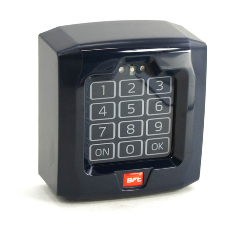
The Tekno K1 Wired keypad allows for access by pin number, RFID car/tag or by operation on the APP. It can operate as a stand-alone
device or work with a Wiegand controller. Supporting NO and NC relay function it can momentarily pulse or latch up to 99 seconds. Two
factor authentication is also available by CARD/TAG then PIN, or alternatively used as standard card/pin unlocking.
Programming Access Code ONLY EM Card and Tag Reader
1. Install the backing plate to the
post or wall using the appropriate
fasteners.
2. After completing wiring install the keypad
to the backing plate clipping into the top clips
from a 45° angle and bring down slowly til
seated.
If only requiring a simple setup of only one common PIN code
the step outlined below can be used to bypass all advanced
steps and quickly add the PIN. Note that 1234 CANNOT be
used as a PIN number.
3. Install the small retaining screw.
About
LED and Buzzer
Quick Reference to add a Common Pin Code
Ready for Admin PI code
1
Second
1
Second
Correct Pin Code In a setting Menu
Relay
Time
1
Second
Bi Bi
Bi
PIN Error
TEKNO
K1
TEKNO
K1
4-6 Digit PIN
9A
0
9A
9
9A
9A
9A
9A
##
* *

Page 2
Type to access admin programming.
Type to access admin programming.
Press to exit programming (solid red indicator is standby)
Press to exit programming (solid red indicator is standby)
Wiegand Reader
Standalone Mode (DEFAULT)
PIN only, No cards
Card then PIN (2FA) , See 2FA Instructions
Relay Toggle Mode (Still standalone but replaces the timed relay
with Latch on/off each correct pin number)
6 DIGIT New Admin PIN
UNIQUE User ID Number
1 -10,000
UNIQUE User ID Number
1 -10,000
Individuals User ID Number
UNIQUE User ID Number
1 -10,000
8-10 Digit Printed Card
Number
1234 CANNOT be used as a
PIN number
8-10 Digit Printed Card
Number
REPEAT New Admin PIN
4-6 Digit PIN
4-6 Digit PIN
Cards only, No pin’s
Card or Pin (Default)
9
9
A
READ CARD
READ CARD
READ CARD
READ CARD
READ CARD
CARD NUMBER
CARD NUMBER
A
A
A
0
0
0
0
3
0
1
2
2
0
2
2
4
1
1
3
9
9
A
U
U
U
U
A
A
A
0
1
2
3
1
9
1
1
0 0000#
#
#
#
#
#
#
#
9
9
A
U
U
U
U
A
A
A
9
9
A
U
U
U
T
T
U
A
A
A
9
9
A
U
U
U
T
U
A
A
A
9
9
A
U
U
U
T
T
U
A
A
A
#
#
#
#
#
#
#
#
# #
#
*
*
#
#
#
*
*
*
*
Set new ADMIN Pin Number
Set the Admin “ADD” Card
Set the Admin “DELETE” Card
Set the system type
Add/Overwrite a common code (NO user ID)
Add a user with a User ID
Delete a user with a User ID
Alarm Time
Alarm Setting
Delete ALL users (NOT the common code)
Administrator
System Functionality (Default Standalone Mode)
PIN Numbers
Authentication and 2FA (Default Card OR Pin)
Relay Unlock/Latching Time (Default 5)
Alarm
0-300(Seconds)
41
0-99(minutes)
0=OFF
42
No Alarm (Default)
Built in buzzer will alarm after 5 incorrect operations for nominated “Alarm
Time”, correct code will turn off alarm.
Lockout the access control system and flash the red led for 10 minutes, wait
10 minutes or power cycle the Tekno K1
60
2
1
1#
#
#

Page 3
1. Swipe the Admin “ADD” Card
2. Swipe all card to be added consecutively
3. Swipe “ADD” card to finish
1. Swipe the Admin “Delete” Card
2. Swipe all card to be deleted consecutively
3. Swipe “DELETE” card to finish
A 2FA user must first swipe there EM card THEN input there pin code followed by #. 2FA Users are added as typical card users with a user ID, Each user
card added has the default PIN number of 1234, this pin number cannot be used and must be changed..
Status Indicator Light
Numerical Key Illumination
Key Press Tone
Illumination and Tone
2FA Users and Changing there PIN
Adding Cards using ADMIN “Add” Card Deleting Cards using ADMIN “Delete” Card
Enabled
Back light on after key press for the nominated time
61
T
3#
T #
Disables the LED indicator in standby only
LED Indicator always present
60
1
2#
#
2-99(seconds)
64Disable tone for users, still works in admin
Tone Enabled
0
1
#
#
Type to access admin programming. Press to exit programming (solid red indicator is standby)
9 9 9 99 9 #
**
Methods to change the PIN number
ST/OP
ANT
ANT
GND
PD/CL
PH
PS
EO/LS01
EC/LSC1
LSO2
LSC2
COM
STOP
COM
OUT 12V LOCK LIGHT M1 M2
COM
1314 15 24
+
++
-
--
12345678910 11 12 13 14 15 16 17 18 19 20 21 22 23 24
oL oc
oA
cd
Operating
Logic
Terminal 3
(ST/OP)
OPEN
OPEN
OPEN
OPEN/
STOP/
CLOSE
Ped. OPEN/
STOP/
CLOSE
CLOSE
CLOSE
Terminal 4
(PD/CL)
St At
+-
COM
N/O
TEKNO
K1
oL oc
oA
cd
Operating
Logic
Terminal 3
(ST/OP)
OPEN
OPEN
OPEN
OPEN/
STOP/
CLOSE
Ped. OPEN/
STOP/
CLOSE
CLOSE
CLOSE
Terminal 4
(PD/CL)
St At
PD/CL
ST/OP
COM
PS/DT
PT/EC
COM
LO
LC
SP/E0
COM
OUT 12V
PC
315
+
-
345678910 11 12 13 14 15
+
-
COM
N/O
TEKNO
K1
Premier SW24 Swing Gate Controller
Premier SL24 Sliding Gate Controller
*READ CARD OLD CODE NEW CODE NEW CODE
# # #
*USER ID OLD CODE NEW CODE NEW CODE
## # #
Default “OLD CODE” is 1234, It cannot unlock and is in
place for reservation purposes.

Page 4
SE NTRY Boom Gate Controller
RLED
--
+12V
OUT
+24V
IN
INPUT AC&DC 16~28V
OUTPUT DCV12/500mA
+
-
POWER CONVERTOR
UP
DOWN
SP (STOP)
GND
COUNT
GND
GND
DETECTOR
GLED
GND
24V
COM
N/O
TEKNO
K1
CLOSE
STOP
DET
OPEN
START
PHOTO
12V DC
COM
14 21
+
-
14 15 16 17 18 19 20 21
For Full Gate operation OPEN and CLOSE connect to
terminal START 19
For OPEN Gate Operation ONLY connect to terminal
OPEN 21
For CLOSE Gate Operation ONLY connect to terminal
CLOSE 20
- AND COM
N/O
+
TEKNO
K1
Premier SL240AC Sliding Gate Controller
Lock Control Power Supply
NO +12V CONTROL + BAT+NC GND CONTROL - BAT-COM PUSH
TEKNO
K1
+12V DC (RED)
GND (BLACK)
COM (Purple)
N/O (Blue)
Magnetic Lock +
Fail Safe Electric Striker +
ALL Electric Striker/Magnetic
Lock Negative
Fail Secure Electric Striker +

Page 5
Exit Button
+12V DC (RED)
GND (BLACK)
GND (BLACK)
also connects DIRECTLY to
the exit button
N/O Button
12V DC Power Supply
TEKNO
K1
OPEN (Yellow)
+12V DC (RED)
GND (BLACK)
GND (BLACK)
also connects DIRECTLY to
the electric striker
12V DC Power Supply
N/C (Orange)
Connects with
Red +12V DC
TEKNO
K1
COM (Purple)
Electric Striker (Direct) FAIL SECURE/POWER OFF TO UNLOCK
Electric Striker (Direct) FAIL SECURE/POWER ON TO UNLOCK
+12V DC (RED)
GND (BLACK)
GND (BLACK)
also connects DIRECTLY to
the electric striker
12V DC Power Supply
N/O (Blue)
Connects with
Red +12V DC
COM (Purple)
TEKNO
K1

Page 6
Administrator User (Home Owner)
Add the Keypad to the ADMINISTRATOR USER Account
1
12
4
3
234
Select
“me”
Select
“Add Device” or “+”
in the top right
If Wi-Fi and Bluetooth are
turned OFF turn them ON and
ensure you connect to your
2.4GHZ Wi-Fi Network.
The Tekno K1 will be automatically
detected, Add the device.
Select
“Home Management”
Download the TuyaSmart App on the Apple App Store or the Google Play Store
Select
“My Home”
Fill in the information
then Save
Type to access
admin programming. If you have changed your
admin code use it instead.
Type to set the Tekno K1 into Wi-Fi
Pairing. The indicator will be flashing green.
9 9
0
9
8
99 9 #
*
56
The device will be added the process can take up to two minutes.
If it failed, ensure the keypad is in excellent proximity to the Wi-Fi
network and ensure the keypad was still in pairing (flashing green)
when the add button is pressed.
Ensure it is the correct Wi-Fi
and enter you Wi-Fi password.
Then register your first user in the APP

Page 7
My Home
Administrator
Total Control including unlocking
and adding/deleting users
Common Member
Control over unlocking only
Sharing access with a User (common users and additional admin’s)
1234
56
Select
“me”
Select
“Home Management”
Select
“My Home”
Select the shared rooms
Ensure any users to be added have installed the APP and registered an account. This will simplify the process and avoid complications.
Select Tuya App Account
Input the registered users email
and details.
Press SAVE when complete
Select “Add Member”

Page 8
Warranty Terms and Conditions
The product is warranted for a period of twelve months (one year) from the date of purchase, unless expressly specified as extended warranty
(extension to the warranty period). The product is to be installed for its intended purpose and for normal use as outlined within the installation
manual, the product warranty is exclusively for defects in manufacturing and manufacturing workmanship. It does not cover out of guidelines use,
natural or other disasters, abnormal weather conditions, damage incurred in shipping or handling, damage caused by disaster such as fire, flood,
wind, earthquake, lightning, excessive voltage, mechanical shock, water damage, damage caused by unauthorized attachment, alterations,
modifications, or foreign objects, damage caused by peripherals (unless such peripherals were supplied by Automation Systems Australia), defects
caused by failure to provide a suitable installation environment for the products, damage caused by usage of the products for purpose other than
those for which it was designed, damage from improper maintenance, damage arising out of any other abuse, mishandling, and improper
application of the products.
At is discretion Automation Systems Australia will require the item determined by the support staff to be returned to base in it original unmodified
condition for a warranty inspection if within the warranty period. A return authorization “RA” number will be provided to be enclosed with the
product in question. The warranty will not cover freight fees to base, customs fees or any labour costs at the installation site but will cover repair or
replacement of the product as seen fit. Automation Systems Australia will cover the freight of the returned item to the original address if deemed as
a warranty repair or replacement item. Any warranty repairs or replacements continue to carry through the remaining warranty period and do not
extend or restart the period.
Under no circumstances shall Automation Systems Australia be liable for any special, incidental, or consequential damages based upon breach of
warranty, breach of contract, negligence, strict liability, or any other legal theory. Such damages include, loss of profits, loss of the product or any
associated equipment, cost of capital, cost of substitute or replacement equipment, facilities or services, down time, purchaser's time, the claims of
third parties, including customers, and injury to property.
This warranty contains the entire warranty and shall be in lieu of any and all other warranties, whether expressed or implied (including all implied
warranties of merchantability or fitness for a particular purpose). And of all other obligations or purporting to act on its behalf to modify or to
change this warranty, nor to assume for it any other warranty or liability concerning this product.
Automation Systems Australia will at its option repair or replace out-of-warranty products at a determined cost which are returned to its base
according to the following conditions. Anyone returning goods to Automation Systems Australia must first obtain an authorization number.
Automation Systems Australia will not accept any shipment whatsoever for which prior authorization has not been obtained. Products which
Automation Systems Australia determines to be repairable will be repaired and returned. A set fee which Automation Systems Australia has been
predetermined and which may be revised from time to time will be charged for each unit repaired. Products which Automation Systems Australia
determines not repairable will be replaced by the nearest equivalent product available at that time. The current market price for the replacement
product will be charged for each replacement unit.
Table of contents
