Northern Lights Lugger M673D User manual
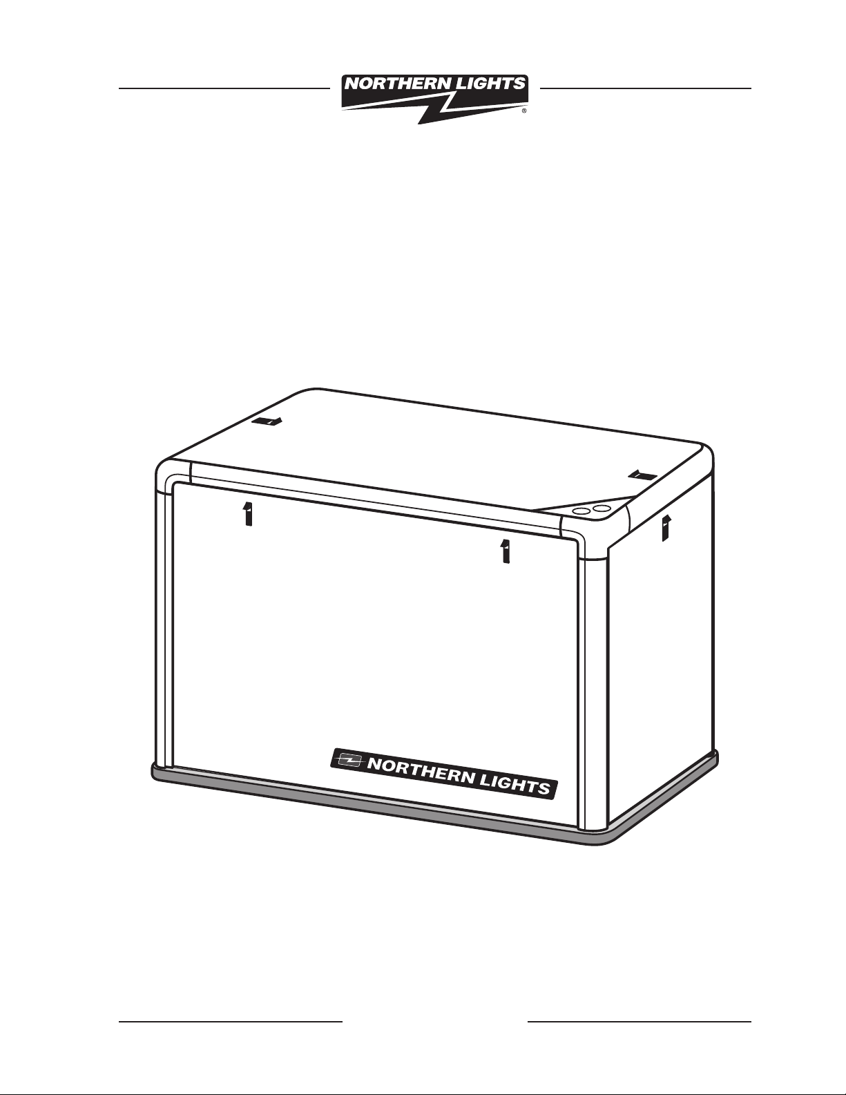
M673D / M673L
Soundshield Assembly Instructions
Corporate Headquarters
4420 14th Avenue N.W.
P.O. Box 70543
Seattle, WA 98107
Tel: (206) 789-3880
Fax: (206) 782-5455
Southeastern U.S.A.
1405 S.W. 6th Court
Suite A
Pompano Beach, FL 33069
Tel: (954) 946-7601
Fax: (954) 946-7409
East Coast Branch
Northern Lights Industrial Park
8 Connector Road
Andover, MA 01810
Tel: (978) 475-7400
Fax: (978) 475-7745
Alaska Branch Office
1200 West Int’l Airport Road
P.O. Box 190208
Anchorage, AK 99519
Tel: (907) 562-2222
Fax: (907) 563-1921
www.northern-lights.com

L612 02/05

L612 02/05
ITEM # DESCRIPTION ADE P/N QTY NOTES
1. Base board 39-78014 1
2. Extrusion, vertical 39-78016 4
3. Extrusion, horizontal, sides 39-78017 2
4. Extrusion, horizontal, ends 39-78024 2
5. Corner casting 05-70001 4
6. Bolting assembly 00-75714 20
7. Rear panel assembly 39-78006 1
8. Front panel assembly 39-78004 1
9. LH side panel assembly 39-78009 1 w/vent box
10. RH side panel assembly 39-78011 1 no vent box
11. Top panel assembly 39-78007 1
12. Penetration panel assembly 39-78008 1
13. Panel retainer bracket, 30R 23-70036 6
14. #10 screw s/s x 5/8”long 12-72002 8
15. Toe bracket, 30R 23-70038 4
16. Hex nut, nylock 1/4-20 14-00112 6
17. Intake hose 1 1/8 ID 18-28001 1
18. Air filter element 24-28002 1
19. Cover, intake 10-28001 1
Specifications
Enclosure:
Length (OA) 32.0 in (814 mm)
Width 20.63 in (524 mm)
Height 21.0 in (533 mm)
Base:
Length 32.5 in (826 mm)
Width 21.2 in (538 mm)
Height 0.75 in (19.05 mm)
Assembled Height:
21.72 in (552 mm)
Assembled Weight (est):
55 lbs (24.9 kg)
M673D/M673L Soundshield
L612 03/03 1
L612 02/05
4
3
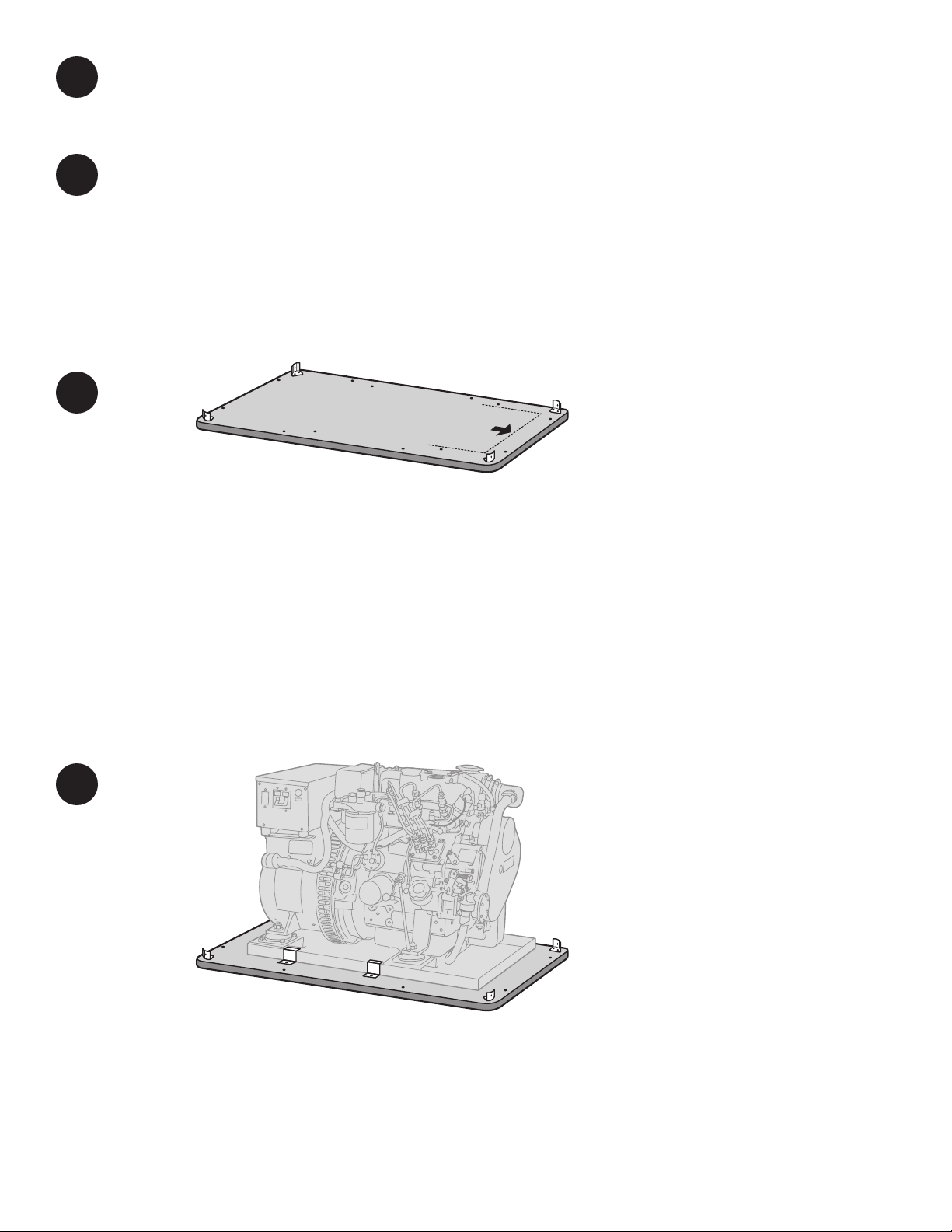
Prior to assembly, inspect all components for damage. Report any damage to the shipping company.
Check the packing list to be sure all parts are included.
Install the base board (item 1) in the vessel in as near a level attitude as possible. Observe the arrow
symbol on the board’s topside surface.This indicates the top and forward end orientation of the
genset / soundshield. Make sure arrow is correctly positioned or the unit will not mount correctly
within the shield.
Install toe bracket (item 15) to each corner of the base board with screws (item 14) into pre-drilled
holes. See figure 1.
Note that there are pre-drilled“through”holes on each side of the baseboard. Use these holes as
guides to drill into the supporting substructure for through-bolting.
Place the generator set onto the baseboard. Note that there are lines present on the base board at
the front and the sides; position the genset base pan to conform with these alignment markings.
Install the hold down clips to the pre-drilled through holes along both sides of the genset base pan.
Use 3/8”or 9 mm bolts of appropriate length to secure the genset and baseboard to the underlying
structure. Loosen lifting eye mounting bolt and tip lifting eye down until lower than highest point on
engine.Tighten lifting eye mounting bolt.
1
2
Select a mounting location in accordance with the guidelines in the IM1000 Installation Manual
(supplied with the generator set). The generator set must typically be mounted on a rigid, flat sur-
face above a strong structure, such as the vessel’s stringers, to minimize vibration transference to the
hull. CAUTION: THE BASEBOARD IS A NONSTRUCTURAL MATERIAL AND MUST BE FULLY
SUPPORTED TO MINIMIZE FLEX.
Note that the generator set is designed for single side service.When viewed from the rear, the right
hand side is the service side and should be exposed for easy maintenance access.
2
L612 02/05
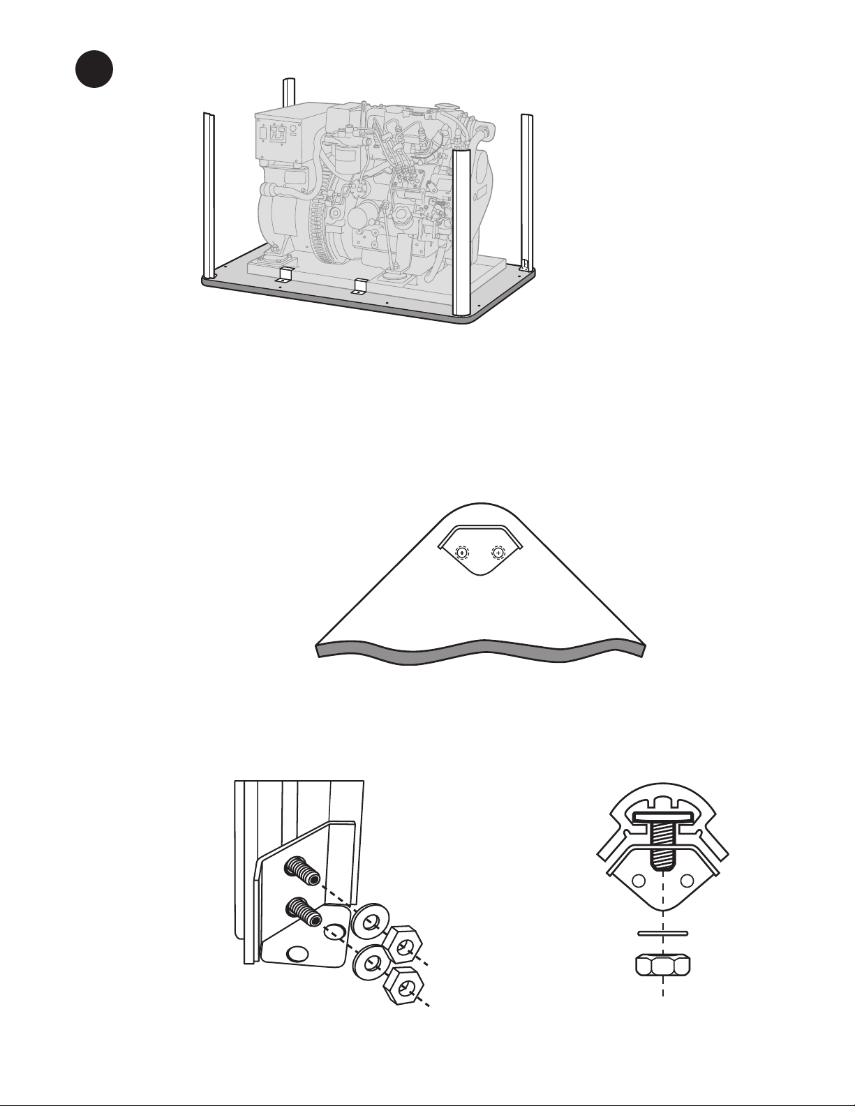
Install the four vertical corner extrusions (item 2) with eight bolting assemblies (item 6) per figures
1A and 1B. Leave hexnuts finger tight.
Figure 1A: Toe bracket shown with vertical extrusion
installed.
3
Figure 1B: Note how the square head of the T-bolt goes
inside the extrusion recess.
5
Figure 1: Typical corner, top view.
L612 02/05
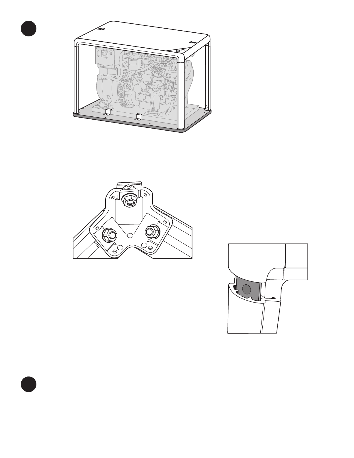
Orient top with triangular shaped penetration plate (item 12) toward front of genset and unattached
corner legs facing down. Install each leg into the top of vertical extrusion. See Figure 3.You may wish
to temporarily remove the top panel (item 11) and set it aside to improve access to the bolting
assemblies and for step 8. Check frame for squareness and tighten all connections.
Figure 3: Note how bolting assembly fits inside vertical
extrusion. Finger tighten only until all four corners have
been fully installed.
6
Note the available leg on each cast corner (item 5) of the pre-assembled enclosure top (items 3, 4, 5,
6, 11, 12, 13 & 16). Loosely install a bolting assembly (item 6) to each of these legs. See Figure 2.
Figure 2: Internal view of corner casting, part of
the pre-assembled top enclosure frame assembly.
Note arrangement of bolting assembly.
4
7

L612 02/05
8
Mount the rear panel assembly (item 7) to the rear of the enclosure frame. Ensure that the panel is
properly fitted into the back of the frame, with the panel surface to extrusion being flush. Rotate
panel retainer brackets (item 13) until they are directly on top of the extrusion flange.Tighten nylock
nuts so the retainer effectively clamps the panel against the extrusion flange. Caution: do not
overtighten retainer clip nuts, as seal damage could occur.
If engine contains pre-installed pre-formed rubber intake hose, proceed to step 10. Check to see if air
filter element protrudes below air box. If it does, it is an older style element and should be replaced
with new filter (item 18) included with kit. Your unit may already be equipped with the new style
filter and if so, replacing it is not required.Take cover (item 19) and insert end (indicated with star)
first into intake manifold opening. Now close the intake cover by pushing the remaining clip into
manifold recess. Remove and discard pre-installed grommet in side of intake box. Take the other end
of the intake hose (item 17) and firmly push it into the hole on the side of the intake box
(see figure 4). Proceed to step 11
5
Figure 4: Air snorkel kit for use in sound shield.
Discard items 17, 18 & 19. Install free end of formed rubber intake hose through grommet on side of
intake box as shown in figure 4.
9
10

L612 02/05
Install connections for exhaust, fuel, AC power leads, DC control panel leads, battery, and water
through holes in the rear panel as shown in drawing (Figure 5) and as described below:
a. Connect the exhaust elbow of the diesel engine to the exhaust system of the vessel.
Pass the two inch exhaust hose through the opening provided in the left mid-section
of the rear panel.
b. Connect the sea water pump to the vessel’s water inlet. Pass a 3/4”hose from the vessel’s
sea water strainer through the lower hole at the bottom left of the rear panel to the sea
water pump inlet fitting.
c. Connect the vessel’s fuel supply and fuel return to the generator set using Coast Guard
approved rubber fuel hoses. Pass these lines through the slot provided at the bottom
right of the rear panel and attach them to the generator set’s 5/16”hose barb fittings.
d. Connect the DC control harness to the engine harness plug. Pass the harness and plug
through the hole at the mid-section of the right side of the rear panel.
e. Connect the 12 volt battery leads to the generator set passing the two leads through the
second hole above the bottom left side on the rear panel.
f. Connect the AC output leads from the generator to the vessel’s power distribution panel.
Pass the two leads through the third hole above the bottom left side of the rear panel.
11
6
Figure 5: Facing the rear panel.

L612 02/05
Note the pre-installed penetration plate (item 12) in the forward right corner of the enclosure
frame top. Reference the plumbing diagram in the mounting and exhaust sections of the IM1000
installation manual.
a. Disconnect the hose from the seawater pump output and from the rubber elbow on the
expansion tank. Install two lengths of 3/4”hose.The hoses must be of adequate length
to allow mounting of a siphon break a minimum of 12 inches above the vessel’s loaded
water line.
b. Pass the seawater pump output hose through the hole in the penetration plate closest
to the front of the shield.The hose from the expansion tank must go through the hole in
the penetration plate closest to the side of the shield.
c. For more information, see the“Exhaust”section of the IM-1000 Installation Manual
included with the generator set.
Start the generator set and run under load to check for leaks of fuel, water, or exhaust gas.
12
13
7
CAUTION: GENERATOR SETS WITH WET EXHAUST THAT ARE INSTALLED NEAR OR BELOW
THE VESSEL’S WATER LINE MUST USE A SIPHON BREAK TO PREVENT BACKFLOW OF WATER
INTO THE ENGINE. THIS BACKFLOW CAN RUIN AN ENGINE AND, POSSIBLY, SINK THE
VESSEL. The penetration plate (item 12) facilitates the siphon break installation as follows:

L612 02/05
14
Install cover panels as shown above.
As you install the panels, observe that there should be a minimum clearance of approximately 1/32”
around the panel perimeter (except at the bottom of the side panels).You may adjust for this by
loosening any number of corner bolting assemblies or toe brackets until fit is satisfactory. Tighten all
connections when done.
Although preset at the factory, one or more panel latches may occasionally need adjustment. Using
a 1/4”box-end wrench, rotate latch striking bolt one-half turn; counter clockwise to tighten panel,
clockwise to loosen panel.
8

L612 02/05

L612 02/05
ITEM # DESCRIPTION ADE P/N QTY NOTES PACKED
1 Base board 39-78014 1 assembled
q
2 Extrusion, vertical 39-78016 4 loose
q
7 Rear panel assembly 39-78006 1 assembled
q
13 Panel retainer bracket, 30R 23-70036 4 installed
q
16 Hex nut, nylock 1/4-20 14-00112 4 installed
q
Enclosure top, assembled. 1
q
Consists of the following parts:
3 Extrusion, horizontal, sides 39-78017 2 assembled –
4 Extrusion, horizontal, ends 39-78024 2 assembled –
5 Corner casting 05-70001 4 assembled –
6 Bolting assembly 00-75714 8 installed –
12 Penetration panel assembly 39-78008 1 installed –
13 Panel retainer bracket, 30R 23-70036 2 installed –
16 Hex nut, nylock 1/4-20 14-00112 2 installed –
11 Top panel assembly 39-78007 1 assembled –
8 Front panel assembly 39-78004 1 assembled
q
9 LH side panel assembly 39-78009 1 assembled
q
10 RH side panel assembly 39-78011 1 assembled
q
6 Bolting assembly 00-75714 12 loose (bagged)
q
14 #10 screw s/s x 5/8”long 12-72002 8 loose (bagged)
q
15 Toe bracket, 30R 23-70038 4 loose (bagged)
q
17. Intake hose 1 1/8 ID 18-28001 1 loose (bagged)
q
18. Air filter element 24-28002 1 loose (bagged)
q
19. Cover intake 10-28001 1 loose (bagged)
q
Packed By : Date :
M673D/M673L Soundshield Packing List
This manual suits for next models
1
Other Northern Lights Enclosure manuals


Popular Enclosure manuals by other brands


Thermaltake
Thermaltake ARMOR REVO GENE VO800M1W2N user manual

Fujitsu
Fujitsu PRIMERGY CX400 S1 Upgrade and maintenance manual

MonsterLabo
MonsterLabo Only The First user manual

LEGRAND
LEGRAND 0 880 62 quick start guide

L-Acoustics
L-Acoustics 12XTi user manual

Thermaltake
Thermaltake Element T VK9000 Series user manual


